Instruction Manual
Page 3
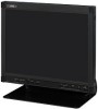
ENGLISH LCD DISPLAY MONITOR LM-170A LM-150A INSTRUCTIONS The illustration of the monitor is of LM-170A.
ENGLISH LCD DISPLAY MONITOR LM-170A LM-150A INSTRUCTIONS The illustration of the monitor is of LM-170A.
Instruction Manual
Page 4
... for a Class B digital device, pursuant to assure your local authorities or for help. FCC NOTICE (U.S.A. If this product, observe the following measures: - Disposal of these "IMPORTANT SAFEGUARDS" carefully before use , and service. only) CAUTION: Changes or modifications not approved by JVC could void the user's authority to provide reasonable protection against harmful interference in a particular installation. These limits...
... for a Class B digital device, pursuant to assure your local authorities or for help. FCC NOTICE (U.S.A. If this product, observe the following measures: - Disposal of these "IMPORTANT SAFEGUARDS" carefully before use , and service. only) CAUTION: Changes or modifications not approved by JVC could void the user's authority to provide reasonable protection against harmful interference in a particular installation. These limits...
Instruction Manual
Page 5
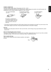
... or local power company. Use only the power cord designated to satisfy FCC rule. For U.S.A. When replacing the fuse, be operated only with the blade screwdriver, and replace the fuse. Doing so may cause malfunction, electric shock or fire. Note for AC 220 - 240 V. ENGLISH POWER CONNECTION The power supply voltage rating of this product is equipped with a grounding-type plug to ensure...
... or local power company. Use only the power cord designated to satisfy FCC rule. For U.S.A. When replacing the fuse, be operated only with the blade screwdriver, and replace the fuse. Doing so may cause malfunction, electric shock or fire. Note for AC 220 - 240 V. ENGLISH POWER CONNECTION The power supply voltage rating of this product is equipped with a grounding-type plug to ensure...
Instruction Manual
Page 6
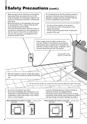
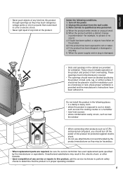
...use the monitor for a long time if the sound is left unattended and unused for long periods of fire or electric shock. • Use only the accessory cord designed for this product near water. • Do not use . To avoid overheating, keep enough space around the monitor (see diagram below). When installing the monitor on a stand Unit: mm (inch) Front view Side view... monitor is of LM-170A. • When the product is used on the wall Unit: mm (inch) Front view Side view 100 (4) 50 (2) 100 100 (4) (4) 100 (4) 4 The main power supply for inserting or removing the power plug....
...use the monitor for a long time if the sound is left unattended and unused for long periods of fire or electric shock. • Use only the accessory cord designed for this product near water. • Do not use . To avoid overheating, keep enough space around the monitor (see diagram below). When installing the monitor on a stand Unit: mm (inch) Front view Side view... monitor is of LM-170A. • When the product is used on the wall Unit: mm (inch) Front view Side view 100 (4) 50 (2) 100 100 (4) (4) 100 (4) 4 The main power supply for inserting or removing the power plug....
Instruction Manual
Page 7
... window • When connecting other hazards. • Upon completion of any service or repairs to this product, ask the service technician to perform safety checks to . Turn off the power of the product and protect it from the wall outlet. 3. b) When the product exhibits a distinct change in installation such as a bookcase or rack unless proper ventilation is provided and the manufacturer's instructions...
... window • When connecting other hazards. • Upon completion of any service or repairs to this product, ask the service technician to perform safety checks to . Turn off the power of the product and protect it from the wall outlet. 3. b) When the product exhibits a distinct change in installation such as a bookcase or rack unless proper ventilation is provided and the manufacturer's instructions...
Instruction Manual
Page 9
ENGLISH Contents Safety Precautions 2 IMPORTANT SAFEGUARDS 2 Maintenance 6 Controls and Features 8 Front panel 8 Rear panel 10 Installation 11 Using the monitor on the stand 11 Installing the monitor on the wall 12 Installing the monitor on the rack 12 How to Use the MAIN MENU 13 MAIN MENU items 13 How to Use the SET-UP MENU 14 SET-UP MENU items 15 How to Use the External Control 17 About the external control 17 How to use the MAKE/TRIGGER terminal 17 Troubleshooting 18 Specifications 20 Dimensions 21 Available computer signals 22 7
ENGLISH Contents Safety Precautions 2 IMPORTANT SAFEGUARDS 2 Maintenance 6 Controls and Features 8 Front panel 8 Rear panel 10 Installation 11 Using the monitor on the stand 11 Installing the monitor on the wall 12 Installing the monitor on the rack 12 How to Use the MAIN MENU 13 MAIN MENU items 13 How to Use the SET-UP MENU 14 SET-UP MENU items 15 How to Use the External Control 17 About the external control 17 How to use the MAKE/TRIGGER terminal 17 Troubleshooting 18 Specifications 20 Dimensions 21 Available computer signals 22 7
Instruction Manual
Page 10
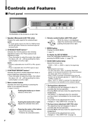
... input. 3 CONTRAST/BRIGHT button*1 Activates the picture contrast adjustment mode or picture brightness adjustment mode. • Press the button to select the mode, then adjust the value (-25 - 00 - +25) by pushing or pressing the button to the beginning) NOTE: • Memorized for the current input or setting. • The position of the LCD panel is 5:4. • When "USER" is selected, horizontal/vertical size and position can be manually adjusted. (+ "SIZE/POSI. Pushing the button left or right. 4 Menu control button Operates the menu...
... input. 3 CONTRAST/BRIGHT button*1 Activates the picture contrast adjustment mode or picture brightness adjustment mode. • Press the button to select the mode, then adjust the value (-25 - 00 - +25) by pushing or pressing the button to the beginning) NOTE: • Memorized for the current input or setting. • The position of the LCD panel is 5:4. • When "USER" is selected, horizontal/vertical size and position can be manually adjusted. (+ "SIZE/POSI. Pushing the button left or right. 4 Menu control button Operates the menu...
Instruction Manual
Page 11
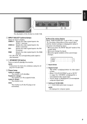
... plug is not connected). 7 About the status display When "STATUS DISPLAY" is set to "AUTO" (+ page 13), "OTHERS" is displayed for a noncompliant video signal input. • "Out of range" is displayed for a noncompliant computer signal input. 3 Setting of SCAN SIZE + "7 SCAN SIZE button/lamp" on page 8 NOTE: • Not displayed for about 5 seconds in Green: The monitor is on and off (standby). p Power lamp Lights in the suspend mode. DVI: Selects the video signal input to the VIDEO 2 terminal. RGB...
... plug is not connected). 7 About the status display When "STATUS DISPLAY" is set to "AUTO" (+ page 13), "OTHERS" is displayed for a noncompliant video signal input. • "Out of range" is displayed for a noncompliant computer signal input. 3 Setting of SCAN SIZE + "7 SCAN SIZE button/lamp" on page 8 NOTE: • Not displayed for about 5 seconds in Green: The monitor is on and off (standby). p Power lamp Lights in the suspend mode. DVI: Selects the video signal input to the VIDEO 2 terminal. RGB...
Instruction Manual
Page 12
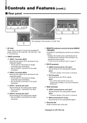
h RGB terminal (D-sub 15-pin) Input terminal for the audio connection. Connect the provided AC power cord to Use the External Control" on LM-170A only 10 c AUDIO 1 terminal (pin jack)* Input terminal for the analog audio signals. • Use the VIDEO 1 terminal for the DVI-D signals. NOTE: • The built-in speaker of LM-170A. 1 1 AC inlet Power input connector. Controls and Features (cont.) 7 Rear panel a b cd 3 2 ef 4 gh 5 6 The illustration of the monitor is of the monitor is...
h RGB terminal (D-sub 15-pin) Input terminal for the audio connection. Connect the provided AC power cord to Use the External Control" on LM-170A only 10 c AUDIO 1 terminal (pin jack)* Input terminal for the analog audio signals. • Use the VIDEO 1 terminal for the DVI-D signals. NOTE: • The built-in speaker of LM-170A. 1 1 AC inlet Power input connector. Controls and Features (cont.) 7 Rear panel a b cd 3 2 ef 4 gh 5 6 The illustration of the monitor is of the monitor is...
Instruction Manual
Page 13
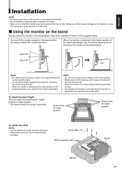
... in the moving parts. • Make sure to detach the stand, see below. To adjust the stand height You can select the stand height-higher position or lower position. • For how to lift the stand up by 90° and place the monitor as illustrated below. Screw (M4 x 10) VESA mounting holes Stand Monitor 11 When the monitor is of LM-170A. 7 Using the monitor on the stand You can place...
... in the moving parts. • Make sure to detach the stand, see below. To adjust the stand height You can select the stand height-higher position or lower position. • For how to lift the stand up by 90° and place the monitor as illustrated below. Screw (M4 x 10) VESA mounting holes Stand Monitor 11 When the monitor is of LM-170A. 7 Using the monitor on the stand You can place...
Instruction Manual
Page 14
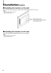
Installation (cont.) 7 Installing the monitor on the rack Use a JVC's RACK MOUNT ADAPTER (RK-C157L1G; VESA mounting holes (See page 21 for the specifications of the mounting holes.) 7 Installing the monitor on the wall Use a commercial wall mounting unit compliant with the VESA standard (100 mm x 100 mm). NOTE: • Detach the stand first. (+ page 11) • Ask your dealer to install. 12 not supplied). NOTE: • Detach the stand first. (+ page 11) • Ask your dealer to install.
Installation (cont.) 7 Installing the monitor on the rack Use a JVC's RACK MOUNT ADAPTER (RK-C157L1G; VESA mounting holes (See page 21 for the specifications of the mounting holes.) 7 Installing the monitor on the wall Use a commercial wall mounting unit compliant with the VESA standard (100 mm x 100 mm). NOTE: • Detach the stand first. (+ page 11) • Ask your dealer to install. 12 not supplied). NOTE: • Detach the stand first. (+ page 11) • Ask your dealer to install.
Instruction Manual
Page 15
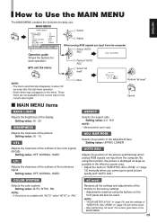
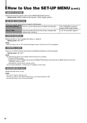
... "all reset" Cancel BACK LIGHT Adjusts the brightness of the monitor to the factory settings. • Adjustments made by using this function, the picture is unstable with "AUTO ADJ." NOTE: • "HOUR METER X100h" (+ page 16) and the settings of the color signals (R/G/B). ADJ. COLOR SYSTEM Selects the color system. Setting value: 00 - 10 CTI. all reset Restores all reset," the screen goes back to Use the MAIN MENU The MAIN MENU contains the...
... "all reset" Cancel BACK LIGHT Adjusts the brightness of the monitor to the factory settings. • Adjustments made by using this function, the picture is unstable with "AUTO ADJ." NOTE: • "HOUR METER X100h" (+ page 16) and the settings of the color signals (R/G/B). ADJ. COLOR SYSTEM Selects the color system. Setting value: 00 - 10 CTI. all reset Restores all reset," the screen goes back to Use the MAIN MENU The MAIN MENU contains the...
Instruction Manual
Page 16
... video signals are not available for each operation. 7 To exit the menu: Next Adjust Select "reset" 7 COLOR TEMP. Operation guide Shows the buttons for the current input or the current input signal. • "HOUR METER X100h" shows the total hors of use of the monitor. How to the previous screen: This item is not selectable. 14 7 NO SYNC FUNCTION Select Select Next Adjust 7 REMOTE SYSTEM 7 STATUS DISPLAY 7 CONTROL LOCK Select Adjust...
... video signals are not available for each operation. 7 To exit the menu: Next Adjust Select "reset" 7 COLOR TEMP. Operation guide Shows the buttons for the current input or the current input signal. • "HOUR METER X100h" shows the total hors of use of the monitor. How to the previous screen: This item is not selectable. 14 7 NO SYNC FUNCTION Select Select Next Adjust 7 REMOTE SYSTEM 7 STATUS DISPLAY 7 CONTROL LOCK Select Adjust...
Instruction Manual
Page 17
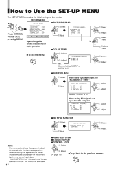
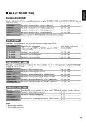
... stripes or flickering by using the CHROMA/PHASE and CONTRAST/BRIGHT buttons on the front panel. SIZE*1 Adjusts the horizontal picture size. -40 - 00 - +40 H. SIZE (4:3)*1 Adjusts the vertical picture size (for 4:3 aspect ratio). -40 - 00 - +40 V. POSI. (4:3)*1 Adjusts the vertical picture position (for 4:3 aspect ratio). -40 - 00 - +40 V. This item is available only when analog RGB signals are input and "SCAN SIZE" (+ page 8) is available only when video signals are input from the computer. to "USER." R DRIVE Adjusts the...
... stripes or flickering by using the CHROMA/PHASE and CONTRAST/BRIGHT buttons on the front panel. SIZE*1 Adjusts the horizontal picture size. -40 - 00 - +40 H. SIZE (4:3)*1 Adjusts the vertical picture size (for 4:3 aspect ratio). -40 - 00 - +40 V. POSI. (4:3)*1 Adjusts the vertical picture position (for 4:3 aspect ratio). -40 - 00 - +40 V. This item is available only when analog RGB signals are input and "SCAN SIZE" (+ page 8) is available only when video signals are input from the computer. to "USER." R DRIVE Adjusts the...
Instruction Manual
Page 18
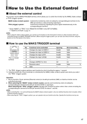
Setting value: MAKE (make contact system), TRIG. (trigger system) NO SYNC FUNCTION Selects the screen status when no signal is activated: - Turning on (or off the monitor - CONTROL LOCK Turns on /off ) the control lock function to "OFF" - Operating the monitor by pressing CHROMA/PHASE button while pressing the MENU button) and turning "CONTROL LOCK" to disable the buttons on !" OFF, SUSPEND (suspend mode), GRAY (gray screen) 5, 20, 60 (seconds, approx.) STATUS DISPLAY Selects whether or...
Setting value: MAKE (make contact system), TRIG. (trigger system) NO SYNC FUNCTION Selects the screen status when no signal is activated: - Turning on (or off the monitor - CONTROL LOCK Turns on /off ) the control lock function to "OFF" - Operating the monitor by pressing CHROMA/PHASE button while pressing the MENU button) and turning "CONTROL LOCK" to disable the buttons on !" OFF, SUSPEND (suspend mode), GRAY (gray screen) 5, 20, 60 (seconds, approx.) STATUS DISPLAY Selects whether or...
Instruction Manual
Page 19
... controlled 1 Changes the input to VIDEO 1 2 Changes the input to VIDEO 2 3 Changes the input to DVI 4 Changes the input to RGB 5- 6 Changes ASPECT to 16:9 7 External control 8 GND Opening Invalid Invalid Invalid Invalid - Off Invalid - Short-circuiting *1 Valid Valid Valid Valid - When selecting the "TRIG." (trigger) system, operate each function by pulse control, that the monitor can also use those functions using the buttons on the front panel or the menu.) 7 How to use...
... controlled 1 Changes the input to VIDEO 1 2 Changes the input to VIDEO 2 3 Changes the input to DVI 4 Changes the input to RGB 5- 6 Changes ASPECT to 16:9 7 External control 8 GND Opening Invalid Invalid Invalid Invalid - Off Invalid - Short-circuiting *1 Valid Valid Valid Valid - When selecting the "TRIG." (trigger) system, operate each function by pulse control, that the monitor can also use those functions using the buttons on the front panel or the menu.) 7 How to use...
Instruction Manual
Page 20
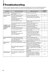
... graphic board of the connected component and set the output correctly. Connect the signal cable firmly. in the MAIN MENU. Change "COLOR TEMP." Or, perform "all reset" in the SET-UP MENU. Is the correct color system selected? Or, adjust "CONTRAST" or "BRIGHT" in the SET-UP MENU. in "PICTURE SUB ADJ." No picture with the power on ? Turn on the power of the computer) is specification? Connect the signal cable firmly. acceptable to the monitor's Check if the input signal...
... graphic board of the connected component and set the output correctly. Connect the signal cable firmly. in the MAIN MENU. Change "COLOR TEMP." Or, perform "all reset" in the SET-UP MENU. Is the correct color system selected? Or, adjust "CONTRAST" or "BRIGHT" in the SET-UP MENU. in "PICTURE SUB ADJ." No picture with the power on ? Turn on the power of the computer) is specification? Connect the signal cable firmly. acceptable to the monitor's Check if the input signal...

Instruction Manual
Page 21
...) Wrong picture position, wrong picture size Has the picture position or size been changed to enable control by the external control connected to the REMOTE terminal? Is the input signal adapted to the monitor's Check if the input signal format is not malfunction. The LCD display is displayed for the Change the input or the input signal. in the SET-UP MENU set to "ON"? Set it to "OFF." appear on the screen after a while. • The red spots, blue spots and green spots...
...) Wrong picture position, wrong picture size Has the picture position or size been changed to enable control by the external control connected to the REMOTE terminal? Is the input signal adapted to the monitor's Check if the input signal format is not malfunction. The LCD display is displayed for the Change the input or the input signal. in the SET-UP MENU set to "ON"? Set it to "OFF." appear on the screen after a while. • The red spots, blue spots and green spots...
Instruction Manual
Page 22
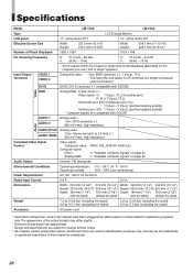
...DVI-D connector x 1 (compatible with DDC2B) Video RGB Analog RGB: D-Sub 15-pin x 1 Video signal: G: 1 V(p-p), 75 Ω (including sync) R, B: 0.7 V(p-p), 75 Ω Horizontal sync (HD)/Composite sync (Cs): 1 V(p-p) - 5 V(p-p) (positive/negative polarity) Vertical sync (VD): 1 V(p-p) - 5 V(p-p) (positive/negative polarity) * Computer signals are used in this frequency range may differ slightly. * Dimensions and weight are approximate. * Design and specifications are subject to change without notice. * All company names and product names mentioned herein are compatible with the stand...
...DVI-D connector x 1 (compatible with DDC2B) Video RGB Analog RGB: D-Sub 15-pin x 1 Video signal: G: 1 V(p-p), 75 Ω (including sync) R, B: 0.7 V(p-p), 75 Ω Horizontal sync (HD)/Composite sync (Cs): 1 V(p-p) - 5 V(p-p) (positive/negative polarity) Vertical sync (VD): 1 V(p-p) - 5 V(p-p) (positive/negative polarity) * Computer signals are used in this frequency range may differ slightly. * Dimensions and weight are approximate. * Design and specifications are subject to change without notice. * All company names and product names mentioned herein are compatible with the stand...
Instruction Manual
Page 24
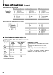
... monitor. Specifications (cont.) Specification of the RGB terminal (D-sub 15-pin) Pin No. does not solve the problem, adjust the items in wrong position or size If "AUTO ADJ." Input signal 1 Red 2 Green 3 Blue 4- 5 GND 6 GND 7 GND 8 GND Pin No. Input signal 9 T.M.D.S Data 1- 10 T.M.D.S Data 1+ 11 T.M.D.S Data 1/3 shield 12 NC 13 NC 14 +5 V Power 15 GND 16 Hot Plug Detect Pin No. Input signal 9 +5 V 10 GND 11 GND 12 DDC data 13 Horizontal sync...
... monitor. Specifications (cont.) Specification of the RGB terminal (D-sub 15-pin) Pin No. does not solve the problem, adjust the items in wrong position or size If "AUTO ADJ." Input signal 1 Red 2 Green 3 Blue 4- 5 GND 6 GND 7 GND 8 GND Pin No. Input signal 9 T.M.D.S Data 1- 10 T.M.D.S Data 1+ 11 T.M.D.S Data 1/3 shield 12 NC 13 NC 14 +5 V Power 15 GND 16 Hot Plug Detect Pin No. Input signal 9 +5 V 10 GND 11 GND 12 DDC data 13 Horizontal sync...

