
Operation Manual
Page 1
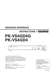
... than instructed in this instruction manual carefully before starting to operate the unit, in order to use : Enter below the serial No. Model No. PK-VS4GD4G Serial No. LCT2540-005A GRAPHICS INTERFACE INSTRUCTIONS PK-VS4GD4G PK-VS4GD4 Visualization Series GRAPHICS INTERFACE MODE STATUS Thank you for purchasing this information for any problems resulting from misuse of the cabinet. We take no responsibility for future reference. Retain this JVC product...
... than instructed in this instruction manual carefully before starting to operate the unit, in order to use : Enter below the serial No. Model No. PK-VS4GD4G Serial No. LCT2540-005A GRAPHICS INTERFACE INSTRUCTIONS PK-VS4GD4G PK-VS4GD4 Visualization Series GRAPHICS INTERFACE MODE STATUS Thank you for purchasing this information for any problems resulting from misuse of the cabinet. We take no responsibility for future reference. Retain this JVC product...
Operation Manual
Page 2
..., care should be required to the operator. - All operating instructions should be routed so that cannot support its installation, use liquid cleaners or aerosol cleaners. Use a damp cloth for its weight securely. If you are not likely to your home, consult your personal safety. This plug will be adhered to radio communications. Power-supply cords should be walked on the label. These...
..., care should be required to the operator. - All operating instructions should be routed so that cannot support its installation, use liquid cleaners or aerosol cleaners. Use a damp cloth for its weight securely. If you are not likely to your home, consult your personal safety. This plug will be adhered to radio communications. Power-supply cords should be walked on the label. These...
Operation Manual
Page 3
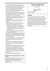
... with SPU80-105 for installation. Adjust only those controls that could result in performance this product from this product to qualified service personnel under the following the operating instructions. Unauthorized substitutions may expose you should be fitted, then follow the instruction given below. 3 POWER CONNECTION Power cord Power supply voltage: AC100 V - 120 V WARNING: Do not cut off the main plug from the wall outlet...
... with SPU80-105 for installation. Adjust only those controls that could result in performance this product from this product to qualified service personnel under the following the operating instructions. Unauthorized substitutions may expose you should be fitted, then follow the instruction given below. 3 POWER CONNECTION Power cord Power supply voltage: AC100 V - 120 V WARNING: Do not cut off the main plug from the wall outlet...
Operation Manual
Page 4
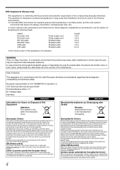
... : JVC Technical Services Europe GmbH Konrad-Adenauer-Allee 1-11 61118 Bad Vilbel Germany ENGLISH Information for Users on the environment and human health which could otherwise be used in the following environments. ● Controlled EMC environment (for electromagnetic compatibility we recommend to use the cables not exceeding the following length: Cables AC power cord DC power cord DVI (x8) cable RS-232C cable USB cable LAN cable Power supply cord Power supply cord Shielded cable Shielded cable...
... : JVC Technical Services Europe GmbH Konrad-Adenauer-Allee 1-11 61118 Bad Vilbel Germany ENGLISH Information for Users on the environment and human health which could otherwise be used in the following environments. ● Controlled EMC environment (for electromagnetic compatibility we recommend to use the cables not exceeding the following length: Cables AC power cord DC power cord DVI (x8) cable RS-232C cable USB cable LAN cable Power supply cord Power supply cord Shielded cable Shielded cable...

Operation Manual
Page 10
... D Power Input Terminal Connect the supplied AC adapter to the projector using a USB cable. F USB Terminal (Type B) This unit can be controlled by connecting it to a computer using a DVI cable. J Cooling Fan CAUTION: Do not block the cooling fan with a dotted number. If the indicator shows "0." OUT : Output terminal for video signals. Changing the settings will cause malfunction. The initialization takes about 15 seconds. G EXT. Connect it to the video source output using a LAN cable...
... D Power Input Terminal Connect the supplied AC adapter to the projector using a USB cable. F USB Terminal (Type B) This unit can be controlled by connecting it to a computer using a DVI cable. J Cooling Fan CAUTION: Do not block the cooling fan with a dotted number. If the indicator shows "0." OUT : Output terminal for video signals. Changing the settings will cause malfunction. The initialization takes about 15 seconds. G EXT. Connect it to the video source output using a LAN cable...
Operation Manual
Page 14
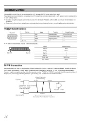
... Connection TCP Port No. 20554 3-way Handshake Projector Control Controlling PC PJREQ Connection Authentication Procedure 14 RS232C Specifications This Unit 1 5 6 9 Pin No. 2 3 5 1, 4, 6-9 RxD TxD GND N/C Signal Function Receive data Transmission data Signal ground - ● PC refers to complete sending within five seconds after you are unable to the controller, such as a personal computer. D0 D1 D2 D3 D4 D5 D6 D7 Start bit Stop bit Mode Data...
... Connection TCP Port No. 20554 3-way Handshake Projector Control Controlling PC PJREQ Connection Authentication Procedure 14 RS232C Specifications This Unit 1 5 6 9 Pin No. 2 3 5 1, 4, 6-9 RxD TxD GND N/C Signal Function Receive data Transmission data Signal ground - ● PC refers to complete sending within five seconds after you are unable to the controller, such as a personal computer. D0 D1 D2 D3 D4 D5 D6 D7 Start bit Stop bit Mode Data...
Operation Manual
Page 18
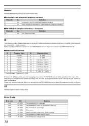
... each of range. Setting separate identification numbers for each PK-VS4GD4G allows independent control of the 16 assignable numbers (from the PK-VS4GD4G when the global ID assignment function (0) is used. Other errors Invalid command at the current mode or setting. This means that tally (response) data is not returned from '1' through 'F') can actually be used when assigning all connected PK-VS4GD4G units for batch operations. Please...
... each of range. Setting separate identification numbers for each PK-VS4GD4G allows independent control of the 16 assignable numbers (from the PK-VS4GD4G when the global ID assignment function (0) is used. Other errors Invalid command at the current mode or setting. This means that tally (response) data is not returned from '1' through 'F') can actually be used when assigning all connected PK-VS4GD4G units for batch operations. Please...
Operation Manual
Page 19
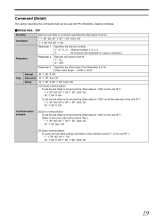
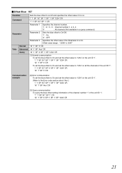
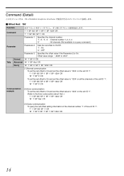
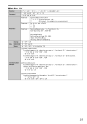
Command (Detail) This section describes the commands that can be used with PK-VS4GD4G, Graphics Interface. Ⅵ Offset Red: 'I55' Function Sets the red offset to on/off and specifies the offset value if it is On. Offset value range: '-2048' to '2047' Normal '@' '1' SP '0' CR ... the offset value if the Parameter 2 is on the unit ID '1'. (Refer to the Error code section about 'Axx'.) '!' '1' SP 'I55' SP '1' SP '1' SP '1234' CR '@' '1' SP 'Axx' CR [3] Query communication To query the red offset setting information of the channel number '1' of the unit ID '1'. '?' '1' SP 'I55' SP '1' CR...
Command (Detail) This section describes the commands that can be used with PK-VS4GD4G, Graphics Interface. Ⅵ Offset Red: 'I55' Function Sets the red offset to on/off and specifies the offset value if it is On. Offset value range: '-2048' to '2047' Normal '@' '1' SP '0' CR ... the offset value if the Parameter 2 is on the unit ID '1'. (Refer to the Error code section about 'Axx'.) '!' '1' SP 'I55' SP '1' SP '1' SP '1234' CR '@' '1' SP 'Axx' CR [3] Query communication To query the red offset setting information of the channel number '1' of the unit ID '1'. '?' '1' SP 'I55' SP '1' CR...
Operation Manual
Page 20
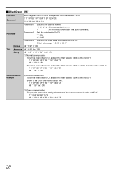
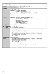
... '@' '1' SP '0' CR Communication example [2] Error communication To set the green offset to On and set the offset value to '1234' on the unit ID '1'. (Refer to the Error code section about 'Axx'.) '!' '1' SP 'I56' SP '1' SP '1' SP '1234' CR '@' '1' SP 'Axx' CR [3] Query communication To query the green offset setting information of the channel number '1' of the unit ID '1'. '?' '1' SP 'I56...
... '@' '1' SP '0' CR Communication example [2] Error communication To set the green offset to On and set the offset value to '1234' on the unit ID '1'. (Refer to the Error code section about 'Axx'.) '!' '1' SP 'I56' SP '1' SP '1' SP '1234' CR '@' '1' SP 'Axx' CR [3] Query communication To query the green offset setting information of the channel number '1' of the unit ID '1'. '?' '1' SP 'I56...
Operation Manual
Page 21
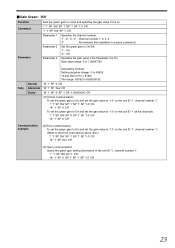
... '0' SP '1' SP '1234' CR '@' '1' SP '0' CR Communication example [2] Error communication To set the blue offset to On and set the offset value to the Error code section about 'Axx'.) '!' '1' SP 'I57' SP '1' SP '1' SP '1234' CR '@' '1' SP 'Axx' CR [3] Query communication To query the blue offset setting information of the channel number '1' of the unit ID '1'. '?' '1' SP 'I57' SP '1' CR '@' '1' SP '0' SP...
... '0' SP '1' SP '1234' CR '@' '1' SP '0' CR Communication example [2] Error communication To set the blue offset to On and set the offset value to the Error code section about 'Axx'.) '!' '1' SP 'I57' SP '1' SP '1' SP '1234' CR '@' '1' SP 'Axx' CR [3] Query communication To query the blue offset setting information of the channel number '1' of the unit ID '1'. '?' '1' SP 'I57' SP '1' CR '@' '1' SP '0' SP...
Operation Manual
Page 22
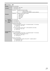
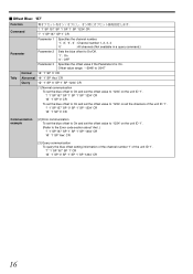
... (2^13 = 8192) The range: 0/8192 to 65535/8192 Normal '@' '1' SP '0' CR Abnormal '@' '1' SP 'Axx' CR Query '@' '1' SP '0' SP '1' SP '1.00000000' CR [1] Normal communication To set the red gain to On and set the gain value to '1.0' on the unit ID '1' channel number '1'. '!' '1' SP 'I58... value if it is On. Ⅵ Gain Red: 'I58' Function Sets the red gain to the Error code section about 'Axx'.) '!' '1' SP 'I58' SP '1' SP '1' SP '1.0' CR '@' '1' SP 'Axx' CR [3] Query communication Query the red gain setting information of the unit ID '1', channel number '1'. '?' '1' SP 'I58' SP '1' CR...
... (2^13 = 8192) The range: 0/8192 to 65535/8192 Normal '@' '1' SP '0' CR Abnormal '@' '1' SP 'Axx' CR Query '@' '1' SP '0' SP '1' SP '1.00000000' CR [1] Normal communication To set the red gain to On and set the gain value to '1.0' on the unit ID '1' channel number '1'. '!' '1' SP 'I58... value if it is On. Ⅵ Gain Red: 'I58' Function Sets the red gain to the Error code section about 'Axx'.) '!' '1' SP 'I58' SP '1' SP '1' SP '1.0' CR '@' '1' SP 'Axx' CR [3] Query communication Query the red gain setting information of the unit ID '1', channel number '1'. '?' '1' SP 'I58' SP '1' CR...
Operation Manual
Page 23
... Parameter 2 is on the unit ID '1', channel number '1'. (Refer to the Error code section about 'Axx'.) '!' '1' SP 'I59' SP '1' SP '1' SP '1.0' CR '@' '1' SP 'Axx' CR [3] Query communication Query the green gain setting information of the unit ID '1', channel number '1'. '?' '1' SP 'I59' SP '1' CR '@' '1' SP '0' SP '1' SP '1' SP '1.0' CR 23 Gain value range: 0 to 7.99987793 Tally Calculating formula: Setting range as integer: 0 to 65535...
... Parameter 2 is on the unit ID '1', channel number '1'. (Refer to the Error code section about 'Axx'.) '!' '1' SP 'I59' SP '1' SP '1' SP '1.0' CR '@' '1' SP 'Axx' CR [3] Query communication Query the green gain setting information of the unit ID '1', channel number '1'. '?' '1' SP 'I59' SP '1' CR '@' '1' SP '0' SP '1' SP '1' SP '1.0' CR 23 Gain value range: 0 to 7.99987793 Tally Calculating formula: Setting range as integer: 0 to 65535...

Operation Manual
Page 24
... '0' SP '1' SP '1.0' CR '@' '1' SP '0' CR Communication example [2] Error communication To set the blue gain to On and set the gain value to '1.0' on the unit ID '1', channel number '1'. (Refer to the Error code section about 'Axx'.) '!' '1' SP 'I5A' SP '1' SP '1' SP '1.0' CR '@' '1' SP 'Axx' CR [3] Query communication Query the blue gain setting information of the unit ID '1', channel number '1'. '?' '1' SP 'I5A' SP '1' CR '@' '1' SP '0' SP...
... '0' SP '1' SP '1.0' CR '@' '1' SP '0' CR Communication example [2] Error communication To set the blue gain to On and set the gain value to '1.0' on the unit ID '1', channel number '1'. (Refer to the Error code section about 'Axx'.) '!' '1' SP 'I5A' SP '1' SP '1' SP '1.0' CR '@' '1' SP 'Axx' CR [3] Query communication Query the blue gain setting information of the unit ID '1', channel number '1'. '?' '1' SP 'I5A' SP '1' CR '@' '1' SP '0' SP...
Operation Manual
Page 25
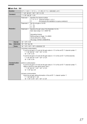
...' SP '1' CR Parameter 1 Specifies the channel number. '1', '2', '3', '4' : Channel number 1, 2, 3, 4 '0' : All channels (Not available in a query command.) Parameter Parameter 2 Specifies the test pattern number. '0' : Test pattern off '1' : Black screen '2' : Blue screen '3' : Color bars '4' : Slash Normal '@' '1' SP '0' CR Tally Abnormal '@' '1' SP 'Axx' CR Query '@' '1' SP '0' SP '1' CR [1] Normal communication To set the test pattern of the unit ID '1', the channel number '1' to Color bars. '!' '1' SP 'I8D...
...' SP '1' CR Parameter 1 Specifies the channel number. '1', '2', '3', '4' : Channel number 1, 2, 3, 4 '0' : All channels (Not available in a query command.) Parameter Parameter 2 Specifies the test pattern number. '0' : Test pattern off '1' : Black screen '2' : Blue screen '3' : Color bars '4' : Slash Normal '@' '1' SP '0' CR Tally Abnormal '@' '1' SP 'Axx' CR Query '@' '1' SP '0' SP '1' CR [1] Normal communication To set the test pattern of the unit ID '1', the channel number '1' to Color bars. '!' '1' SP 'I8D...
Operation Manual
Page 26
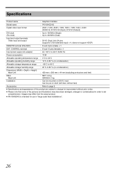
...) : Up to page 9. ● Specifications and appearance of the pictures and illustrations may differ from the actual product. ● PK-VS4GD4G is intended for improvement without feet) Accessories : Refer to 330 MHz (Dual) Input and output terminals Video input and output : DVI-D (Dual Link) 24 pins (supports 12-bit extended input) × 4, (does not support HDCP) REMOTE terminal (RS-232C) : D-sub 9 pins (male) × 1 EXT. Images...
...) : Up to page 9. ● Specifications and appearance of the pictures and illustrations may differ from the actual product. ● PK-VS4GD4G is intended for improvement without feet) Accessories : Refer to 330 MHz (Dual) Input and output terminals Video input and output : DVI-D (Dual Link) 24 pins (supports 12-bit extended input) × 4, (does not support HDCP) REMOTE terminal (RS-232C) : D-sub 9 pins (male) × 1 EXT. Images...
Operation Manual
Page 42
...' CR '?' '1' SP 'I55' SP '1' CR Parameter 1 Specifies the channel number. '1', '2', '3', '4' : Channel number 1, 2, 3, 4 '0' : All channels (Not available in a query command.) Parameter Parameter 2 Sets the red offset to the Error code section about 'Axx'.) '!' '1' SP 'I55' SP '1' SP '1' SP '1234' CR '@' '1' SP 'Axx' CR [3] Query communication To query the red offset setting information of the channel number '1' of the unit ID '1'. '?' '1' SP 'I55' SP '1' CR '@' '1' SP '0' SP...
...' CR '?' '1' SP 'I55' SP '1' CR Parameter 1 Specifies the channel number. '1', '2', '3', '4' : Channel number 1, 2, 3, 4 '0' : All channels (Not available in a query command.) Parameter Parameter 2 Sets the red offset to the Error code section about 'Axx'.) '!' '1' SP 'I55' SP '1' SP '1' SP '1234' CR '@' '1' SP 'Axx' CR [3] Query communication To query the red offset setting information of the channel number '1' of the unit ID '1'. '?' '1' SP 'I55' SP '1' CR '@' '1' SP '0' SP...

Operation Manual
Page 43
... '?' '1' SP 'I56' SP '1' CR Parameter 1 Specifies the channel number. '1', '2', '3', '4' : Channel number 1, 2, 3, 4 '0' : All channels (Not available in a query command.) Parameter Parameter 2 Sets the red offset to the Error code section about 'Axx'.) '!' '1' SP 'I56' SP '1' SP '1' SP '1234' CR '@' '1' SP 'Axx' CR [3] Query communication To query the green offset setting information of the channel number '1' of the unit ID '1'. '!' '1' SP 'I56' SP '0' SP '1' SP '1234...
... '?' '1' SP 'I56' SP '1' CR Parameter 1 Specifies the channel number. '1', '2', '3', '4' : Channel number 1, 2, 3, 4 '0' : All channels (Not available in a query command.) Parameter Parameter 2 Sets the red offset to the Error code section about 'Axx'.) '!' '1' SP 'I56' SP '1' SP '1' SP '1234' CR '@' '1' SP 'Axx' CR [3] Query communication To query the green offset setting information of the channel number '1' of the unit ID '1'. '!' '1' SP 'I56' SP '0' SP '1' SP '1234...
Operation Manual
Page 44
...' CR '?' '1' SP 'I57' SP '1' CR Parameter 1 Specifies the channel number. '1', '2', '3', '4' : Channel number 1, 2, 3, 4 '0' : All channels (Not available in a query command.) Parameter Parameter 2 Sets the blue offset to the Error code section about 'Axx'.) '!' '1' SP 'I57' SP '1' SP '1' SP '1234' CR '@' '1' SP 'Axx' CR [3] Query communication To query the blue offset setting information of the channel number '1' of the unit ID '1'. '!' '1' SP 'I57' SP '0' SP '1' SP '1234...
...' CR '?' '1' SP 'I57' SP '1' CR Parameter 1 Specifies the channel number. '1', '2', '3', '4' : Channel number 1, 2, 3, 4 '0' : All channels (Not available in a query command.) Parameter Parameter 2 Sets the blue offset to the Error code section about 'Axx'.) '!' '1' SP 'I57' SP '1' SP '1' SP '1234' CR '@' '1' SP 'Axx' CR [3] Query communication To query the blue offset setting information of the channel number '1' of the unit ID '1'. '!' '1' SP 'I57' SP '0' SP '1' SP '1234...
Operation Manual
Page 45
... channel number. '1', '2', '3', '4' : Channel number 1, 2, 3, 4 '0' : All channels (Not available in a query command.) Parameter Parameter 2 Parameter 3 Set the red gain to the Error code section about 'Axx'.) '!' '1' SP 'I58' SP '1' SP '1' SP '1.0' CR '@' '1' SP 'Axx' CR [3] Query communication Query the red gain setting information of the unit ID '1', channel number '1'. '?' '1' SP 'I58' SP '1' CR '@' '1' SP '0' SP '1' SP '1' SP '1.0' CR 17 Gain value range: 0 to 7.99987793 Tally Calculating formula: Setting range...
... channel number. '1', '2', '3', '4' : Channel number 1, 2, 3, 4 '0' : All channels (Not available in a query command.) Parameter Parameter 2 Parameter 3 Set the red gain to the Error code section about 'Axx'.) '!' '1' SP 'I58' SP '1' SP '1' SP '1.0' CR '@' '1' SP 'Axx' CR [3] Query communication Query the red gain setting information of the unit ID '1', channel number '1'. '?' '1' SP 'I58' SP '1' CR '@' '1' SP '0' SP '1' SP '1' SP '1.0' CR 17 Gain value range: 0 to 7.99987793 Tally Calculating formula: Setting range...
Operation Manual
Page 47
... channel number. '1', '2', '3', '4' : Channel number 1, 2, 3, 4 '0' : All channels (Not available in a query command.) Parameter Parameter 2 Parameter 3 Set the blue gain to the Error code section about 'Axx'.) '!' '1' SP 'I5A' SP '1' SP '1' SP '1.0' CR '@' '1' SP 'Axx' CR [3] Query communication Query the blue gain setting information of the unit ID '1', channel number '1'. '?' '1' SP 'I5A' SP '1' CR '@' '1' SP '0' SP '1' SP '1' SP '1.0' CR 19 Gain value range: 0 to 7.99987793 Tally Calculating formula: Setting range...
... channel number. '1', '2', '3', '4' : Channel number 1, 2, 3, 4 '0' : All channels (Not available in a query command.) Parameter Parameter 2 Parameter 3 Set the blue gain to the Error code section about 'Axx'.) '!' '1' SP 'I5A' SP '1' SP '1' SP '1.0' CR '@' '1' SP 'Axx' CR [3] Query communication Query the blue gain setting information of the unit ID '1', channel number '1'. '?' '1' SP 'I5A' SP '1' CR '@' '1' SP '0' SP '1' SP '1' SP '1.0' CR 19 Gain value range: 0 to 7.99987793 Tally Calculating formula: Setting range...