Instructions
Page 3
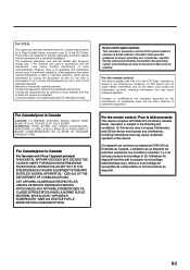
...is subject to the following two conditions: (1) this device may not cause interference, and (2) this device must accept any interference received, including interference that interference will not occur in particular, specifies that may not cause harmful interference, and (2) this device must ... or an experienced radio/TV technician for a Class B digital device, pursuant to the following measures: Reorient or relocate the receiving antenna. For the remote control: This device complies with the instructions, may cause undesired operation. This equipment generates, uses and...
...is subject to the following two conditions: (1) this device may not cause interference, and (2) this device must accept any interference received, including interference that interference will not occur in particular, specifies that may not cause harmful interference, and (2) this device must ... or an experienced radio/TV technician for a Class B digital device, pursuant to the following measures: Reorient or relocate the receiving antenna. For the remote control: This device complies with the instructions, may cause undesired operation. This equipment generates, uses and...

Instructions
Page 4
...our JVC products. Poor ventilation could cause your dealer before operating any further. • Do not use the remote control outdoors or install the speakers outdoors. • When operating the receiver from a place where you can connect two pairs of front speakers to the RX-DP15B, .... You can enjoy 7.1-channel surround by expanding the sampling frequency to surprise other JVC audio/video components from this receiver will generate heat inside . COMPU LINK/TEXT COMPU LINK/AV COMPU LINK remote control systems These COMPU LINK remote control systems allow you are accurately...
...our JVC products. Poor ventilation could cause your dealer before operating any further. • Do not use the remote control outdoors or install the speakers outdoors. • When operating the receiver from a place where you can connect two pairs of front speakers to the RX-DP15B, .... You can enjoy 7.1-channel surround by expanding the sampling frequency to surprise other JVC audio/video components from this receiver will generate heat inside . COMPU LINK/TEXT COMPU LINK/AV COMPU LINK remote control systems These COMPU LINK remote control systems allow you are accurately...

Instructions
Page 5
...2 Source to Play 31 Adjusting the Zone 2 Volume 31 Activating the Zone 2 Front Speakers 32 Muting the Zone 2 Sound 32 Receiving Radio Broadcasts 33 Tuning in to Stations Manually 33 Using Preset Tuning 34 Selecting the FM Reception Mode 34 Basic Settings 35 Setup Menu...or in Zone 2 64 7 Searching for a Disc (Only for the CD player 65 7 Entering the Disc Information 66 AV COMPU LINK Remote Control System .... 68 Operating JVC's Audio/Video Components ... 71 Operating Audio Components 71 Operating Video Components 73 Operating Other Manufacturers' Equipment ... 74 Changing the Preset...
...2 Source to Play 31 Adjusting the Zone 2 Volume 31 Activating the Zone 2 Front Speakers 32 Muting the Zone 2 Sound 32 Receiving Radio Broadcasts 33 Tuning in to Stations Manually 33 Using Preset Tuning 34 Selecting the FM Reception Mode 34 Basic Settings 35 Setup Menu...or in Zone 2 64 7 Searching for a Disc (Only for the CD player 65 7 Entering the Disc Information 66 AV COMPU LINK Remote Control System .... 68 Operating JVC's Audio/Video Components ... 71 Operating Audio Components 71 Operating Video Components 73 Operating Other Manufacturers' Equipment ... 74 Changing the Preset...

Instructions
Page 6
... TUNING 5 RIGHT / PRESET 5 u SET / MEMORY EXIT / FM MODE i o ;a s df g STANDBY STANDBY/ ON CC CONVERTER ZONE 1 ON/OFF ZONE 2 ON/OFF RX-DP15 SPEAKERS 1 INPUT MODE / INPUT ATT SPEAKER 2 / ZONE 2 ZONE 2 CONTROL THX EX/ES/7.1 SURROUND DSP SURR/DSP OFF ANALOG DIRECT ADJUST MENU DOWN / TUNING ∞... ∞ UP / TUNING 5 RIGHT / PRESET 5 SET / MEMORY EXIT / FM MODE DIMMER DOOR UP DOOR DOWN MASTER VOLUME PHONES AUDIO/VIDEO CONTROL RECEIVER DIGITAL S-VIDEO VIDEO VIDEO L-AUDIO-R h DOOR DOWN To open the front door, press DOOR DOWN. (For more details, see page 20.) jk l ...
... TUNING 5 RIGHT / PRESET 5 u SET / MEMORY EXIT / FM MODE i o ;a s df g STANDBY STANDBY/ ON CC CONVERTER ZONE 1 ON/OFF ZONE 2 ON/OFF RX-DP15 SPEAKERS 1 INPUT MODE / INPUT ATT SPEAKER 2 / ZONE 2 ZONE 2 CONTROL THX EX/ES/7.1 SURROUND DSP SURR/DSP OFF ANALOG DIRECT ADJUST MENU DOWN / TUNING ∞... ∞ UP / TUNING 5 RIGHT / PRESET 5 SET / MEMORY EXIT / FM MODE DIMMER DOOR UP DOOR DOWN MASTER VOLUME PHONES AUDIO/VIDEO CONTROL RECEIVER DIGITAL S-VIDEO VIDEO VIDEO L-AUDIO-R h DOOR DOWN To open the front door, press DOOR DOWN. (For more details, see page 20.) jk l ...

Instructions
Page 7
... indicators • Indicate the current Surround/THX/DSP mode setting. 6 TUNED indicator (33) • Lights up when a station is received. 7 STEREO indicator (33) • Lights up when an FM stereo station is received. 8 AUTO MUTING indicator (34) • Lights up when Midnight Mode is in use . 0 ONE TOUCH OPERATION indicator (44) •...
... indicators • Indicate the current Surround/THX/DSP mode setting. 6 TUNED indicator (33) • Lights up when a station is received. 7 STEREO indicator (33) • Lights up when an FM stereo station is received. 8 AUTO MUTING indicator (34) • Lights up when Midnight Mode is in use . 0 ONE TOUCH OPERATION indicator (44) •...
Instructions
Page 8
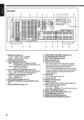
...12) 7 RF REMOTE ANTENNA terminal and BAND 1/2 selector (17) 8 FM/AM ANTENNA terminals (7, 8) 9 COMPU LINK-4 (SYNCHRO) terminals (61, 63) p AV COMPU LINK-III terminals (68) q TEXT COMPU LINK terminals (63) w IR OUT terminal (18, 68) e CTRL OUT +12V terminal • This terminal... transmits +12V voltage signals (maximum output current: 10 mA). r IR IN terminal • This terminal is only for systematic operation between this receiver and the connected component (availability of this terminal also turns on the conncted component). English Rear Panel 12 3 4 5 67 8 9 p q ...
...12) 7 RF REMOTE ANTENNA terminal and BAND 1/2 selector (17) 8 FM/AM ANTENNA terminals (7, 8) 9 COMPU LINK-4 (SYNCHRO) terminals (61, 63) p AV COMPU LINK-III terminals (68) q TEXT COMPU LINK terminals (63) w IR OUT terminal (18, 68) e CTRL OUT +12V terminal • This terminal... transmits +12V voltage signals (maximum output current: 10 mA). r IR IN terminal • This terminal is only for systematic operation between this receiver and the connected component (availability of this terminal also turns on the conncted component). English Rear Panel 12 3 4 5 67 8 9 p q ...
Instructions
Page 9
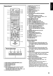
... up when you press a button on the remote control, with the ZONE 1/ZONE 2 (LEARN/TRANSMIT) selector set to "ZONE 1." This remote control cannot operate the receiver or other components, but can be used only for about 5 seconds.) 6 English appears. VCR 1 (STANDBY/ON) button (73, 75, 80) a TV/CATV/DBS (STANDBY/ON.../ UP PAUSE TV/VIDEO TV VOL CHANNEL MUTING VOLUME SETUP MENU TEXT DISPLAY DVD MENU SET LIGHT ADJUST MENU EXIT RM-SRXDP20J REMOTE CONTROL A/V CONTROL RECEIVER i o ;
... up when you press a button on the remote control, with the ZONE 1/ZONE 2 (LEARN/TRANSMIT) selector set to "ZONE 1." This remote control cannot operate the receiver or other components, but can be used only for about 5 seconds.) 6 English appears. VCR 1 (STANDBY/ON) button (73, 75, 80) a TV/CATV/DBS (STANDBY/ON.../ UP PAUSE TV/VIDEO TV VOL CHANNEL MUTING VOLUME SETUP MENU TEXT DISPLAY DVD MENU SET LIGHT ADJUST MENU EXIT RM-SRXDP20J REMOTE CONTROL A/V CONTROL RECEIVER i o ;
Instructions
Page 10
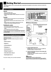
...between -5˚C and 35˚C. • Make sure there is missing, contact your hands are supplied for the receiver. Poor ventilation could overheat and damage the receiver. Do not connect the AC power cord until all components. • Read the manuals supplied with an Outdoor FM ... is level, well-ventilated and free from moisture and dust. • The temperature around the receiver. Handling the receiver • Do not insert any item is good ventilation around the receiver must be connected to rain or moisture. Connecting the FM and AM Antennas Rear view FM Antenna...
...between -5˚C and 35˚C. • Make sure there is missing, contact your hands are supplied for the receiver. Poor ventilation could overheat and damage the receiver. Do not connect the AC power cord until all components. • Read the manuals supplied with an Outdoor FM ... is level, well-ventilated and free from moisture and dust. • The temperature around the receiver. Handling the receiver • Do not insert any item is good ventilation around the receiver must be connected to rain or moisture. Connecting the FM and AM Antennas Rear view FM Antenna...

Instructions
Page 13
... 2 / ZONE 2 SPEAKERS RIGHT LEFT CENTER SPEAKER To use the speaker with the above connection, see page 19). • To connect the front speakers in this receiver as follows: • To connect the second pair of the PREOUT SURR BACK jacks.) Connecting a subwoofer You can be used as the pre-amplifier (control...
... 2 / ZONE 2 SPEAKERS RIGHT LEFT CENTER SPEAKER To use the speaker with the above connection, see page 19). • To connect the front speakers in this receiver as follows: • To connect the second pair of the PREOUT SURR BACK jacks.) Connecting a subwoofer You can be used as the pre-amplifier (control...

Instructions
Page 14
...individual components, refer also to the manuals supplied with an MM (moving -coil) type must be distorted. Direct connection may be connected to this receiver may result in insufficient volume. Analog Connections Audio component connections Use the cables with RCA pin plugs (not supplied). • Connect the white plug...an MC (moving -magnet) type cartridge. CAUTION: If you connect a sound-enhancing device such as a graphic equalizer between the source components and this receiver, the sound output through this receiver through a commercial head amplifier or step-up transformer.
...individual components, refer also to the manuals supplied with an MM (moving -coil) type must be distorted. Direct connection may be connected to this receiver may result in insufficient volume. Analog Connections Audio component connections Use the cables with RCA pin plugs (not supplied). • Connect the white plug...an MC (moving -magnet) type cartridge. CAUTION: If you connect a sound-enhancing device such as a graphic equalizer between the source components and this receiver, the sound output through this receiver through a commercial head amplifier or step-up transformer.

Instructions
Page 15
...channel output Note: If the external component connected to the EXT 7.1CH IN jacks and this type can use any of this receiver are used, the unit automatically gives priority to be emitted only through an external component connected to view the pictures through the ... L SUB WOOFER SURR R CENTER L R SURR BACK R L L EXT 7.1CH IN IMPORTANT: This receiver is equipped with RCA pin plugs (not supplied). You can be connected using the cords of this receiver. However, observe the following points when make connections: • Composite video signals and S-video signals can ...
...channel output Note: If the external component connected to the EXT 7.1CH IN jacks and this type can use any of this receiver are used, the unit automatically gives priority to be emitted only through an external component connected to view the pictures through the ... L SUB WOOFER SURR R CENTER L R SURR BACK R L L EXT 7.1CH IN IMPORTANT: This receiver is equipped with RCA pin plugs (not supplied). You can be connected using the cords of this receiver. However, observe the following points when make connections: • Composite video signals and S-video signals can ...

Instructions
Page 19
English Digital Connections This receiver is equipped with the following components: - 1 (coaxial) : For DVD player - 2 (coaxial) : For CD player - 3 (coaxial) : For digital TV broadcast tuner - 4 (optical) : For CD recorder - 5 (optical) : ... target component also as described in "Analog Connections" (see page 11). • When you want to operate the VCR, TV or DVD player using the AV COMPU LINK remote control system, connect the target component also as described in "Analog Connections" (see page 12). IMPORTANT: • When connecting the DVD player...
English Digital Connections This receiver is equipped with the following components: - 1 (coaxial) : For DVD player - 2 (coaxial) : For CD player - 3 (coaxial) : For digital TV broadcast tuner - 4 (optical) : For CD recorder - 5 (optical) : ... target component also as described in "Analog Connections" (see page 11). • When you want to operate the VCR, TV or DVD player using the AV COMPU LINK remote control system, connect the target component also as described in "Analog Connections" (see page 12). IMPORTANT: • When connecting the DVD player...

Instructions
Page 20
... 2). If this receiver (more conveniently. In addition, the IR signal transmitter reduces the possibility of malfunction. • The IR signal transmitter may differ depending on the other components from such an RF remote control system, which could cause your JVC dealer or the nearest JVC Service Center. Insert... same time. The RF rod antenna can retransmit the IR signals. Moreover, RF signals can transmit both on the receiver. Find a place where you to use the AV COMPU LINK remote control system, and to use an extension cord (not supplied). 2. English Using the RF Rod...
... 2). If this receiver (more conveniently. In addition, the IR signal transmitter reduces the possibility of malfunction. • The IR signal transmitter may differ depending on the other components from such an RF remote control system, which could cause your JVC dealer or the nearest JVC Service Center. Insert... same time. The RF rod antenna can retransmit the IR signals. Moreover, RF signals can transmit both on the receiver. Find a place where you to use the AV COMPU LINK remote control system, and to use an extension cord (not supplied). 2. English Using the RF Rod...

Instructions
Page 21
...: 60˚ Vertically: 60˚ 15° 45° 30° 30° 1. If the remote control cannot transmit signals or operate the receiver correctly, replace the batteries. Use two LR6(AM3)/L40(15A) type (alkaline) dry-cell batteries. When unplugging the cord, always grasp the plug so as...IR 10mA MAX IN Putting Batteries in voltage. • Always replace both batteries at a distance of approx. 60° Less than 3 m (10 feet) COMPU AV TEXT LINK-4 COMPU COMPU (SYNCHRO) LINK- Keep the power cord away from the connecting cables and the antenna. When you do not press any button...
...: 60˚ Vertically: 60˚ 15° 45° 30° 30° 1. If the remote control cannot transmit signals or operate the receiver correctly, replace the batteries. Use two LR6(AM3)/L40(15A) type (alkaline) dry-cell batteries. When unplugging the cord, always grasp the plug so as...IR 10mA MAX IN Putting Batteries in voltage. • Always replace both batteries at a distance of approx. 60° Less than 3 m (10 feet) COMPU AV TEXT LINK-4 COMPU COMPU (SYNCHRO) LINK- Keep the power cord away from the connecting cables and the antenna. When you do not press any button...
Instructions
Page 22
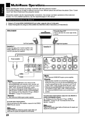
...two different places (we call these two places "Zone 1 (main room)" and "Zone 2 (sub-room)") by using a cable with this receiver. Left front speaker Connection Å Connect the input jacks of long audio cables/long speaker signal cables will deteriorate the signals and degrade the sound...To use the Zone 2 front speakers Turn on and select the correct input for Zone 1, this manual. English Multi-Room Operations Before operating this receiver any further, be fixed or variable by setting it on the Setup Menu. (See "w Setting the Zone 2/Speakers 2 Usage-ZONE 2/ SPEAKER 2"...
...two different places (we call these two places "Zone 1 (main room)" and "Zone 2 (sub-room)") by using a cable with this receiver. Left front speaker Connection Å Connect the input jacks of long audio cables/long speaker signal cables will deteriorate the signals and degrade the sound...To use the Zone 2 front speakers Turn on and select the correct input for Zone 1, this manual. English Multi-Room Operations Before operating this receiver any further, be fixed or variable by setting it on the Setup Menu. (See "w Setting the Zone 2/Speakers 2 Usage-ZONE 2/ SPEAKER 2"...

Instructions
Page 24
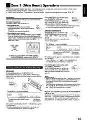
... up . For more details, see page 43), the MASTER VOLUME control will not work for the Zone 2 source. From the remote control: When operating the receiver using the remote control, the display on the Zone 2 operations, see page 43), the VOLUME +/- Press AUDIO (ON).
... up . For more details, see page 43), the MASTER VOLUME control will not work for the Zone 2 source. From the remote control: When operating the receiver using the remote control, the display on the Zone 2 operations, see page 43), the VOLUME +/- Press AUDIO (ON).
Instructions
Page 25
... automatically closes. (The ZONE 1 ON/ OFF and/or ZONE 2 ON/OFF lamp on the unit goes off.) Notes: • Before you turn off the receiver with multi-room operation mode (either ZONE 1 or ZONE 2) for the Zone 2 (sub-room) operations. • Before performing Zone 1 operations, it is ...recommended to finish the basic settings on the receiver. To turn the power off .) • A small amount of power is consumed in standby mode. The last Zone 1 source is not shown in the main...
... automatically closes. (The ZONE 1 ON/ OFF and/or ZONE 2 ON/OFF lamp on the unit goes off.) Notes: • Before you turn off the receiver with multi-room operation mode (either ZONE 1 or ZONE 2) for the Zone 2 (sub-room) operations. • Before performing Zone 1 operations, it is ...recommended to finish the basic settings on the receiver. To turn the power off .) • A small amount of power is consumed in standby mode. The last Zone 1 source is not shown in the main...
Instructions
Page 26
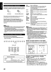
... front speakers indicator(s) also go(es) off after about 1 minute. Notes: • If you have turned off Zone 1 with an asterisk (*), the receiver automatically turns on. To use the DVD MULTI playback mode, see page 60. VIDEO : Selects the video component connected to the VCR 2 IN jacks.... signal indicators on the display By checking the following indicators, you can easily confirm which speakers you press one of "SB" are coming into this receiver for details, see "Changing the Source Name" on the speaker setting (for Zone 1 operations again, press ZONE 1 ON/OFF again (the ZONE...
... front speakers indicator(s) also go(es) off after about 1 minute. Notes: • If you have turned off Zone 1 with an asterisk (*), the receiver automatically turns on. To use the DVD MULTI playback mode, see page 60. VIDEO : Selects the video component connected to the VCR 2 IN jacks.... signal indicators on the display By checking the following indicators, you can easily confirm which speakers you press one of "SB" are coming into this receiver for details, see "Changing the Source Name" on the speaker setting (for Zone 1 operations again, press ZONE 1 ON/OFF again (the ZONE...
Instructions
Page 27
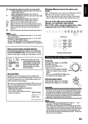
... VOLUME VOLUME clockwise. For example, when adjusting the volume level in . Notes: • The volume level can be adjusted within the range of this receiver. It is selected: Always lights up. S : Lights up when the monaural surround channel signal comes in Zone 2 from a video component such as...- - L CR SUBWFR LFE LS RS SB Ex. About Dual Mono Dual Mono can be easily understood when you have turned off the receiver with those analog formats). DUAL indicator DUAL L DGTL AUTO R SUBWFR DIGITAL Selecting different sources for picture and sound While watching pictures from a...
... VOLUME VOLUME clockwise. For example, when adjusting the volume level in . Notes: • The volume level can be adjusted within the range of this receiver. It is selected: Always lights up. S : Lights up when the monaural surround channel signal comes in Zone 2 from a video component such as...- - L CR SUBWFR LFE LS RS SB Ex. About Dual Mono Dual Mono can be easily understood when you have turned off the receiver with those analog formats). DUAL indicator DUAL L DGTL AUTO R SUBWFR DIGITAL Selecting different sources for picture and sound While watching pictures from a...

Instructions
Page 29
... press RIGHT (or LEFT) on the unit or pressing VOLUME +/- When "DOLBY DIGITAL" or "DTS SURROUND" is in . : Lights up . The receiver automatically detects the incoming signals. When selecting "DIGITAL AUTO," the following symptoms may occur: • Sound does not come in Zone 1 and headphones connected.... When the source is "VIDEO." To restore the sound, press MUTING again so that the INPUT ATT indicator lights up when the receiver cannot recognize the digital signal format of the selected indicator will be distorted. English DIGITAL AUTO : Select this for the analog input mode...
... press RIGHT (or LEFT) on the unit or pressing VOLUME +/- When "DOLBY DIGITAL" or "DTS SURROUND" is in . : Lights up . The receiver automatically detects the incoming signals. When selecting "DIGITAL AUTO," the following symptoms may occur: • Sound does not come in Zone 1 and headphones connected.... When the source is "VIDEO." To restore the sound, press MUTING again so that the INPUT ATT indicator lights up when the receiver cannot recognize the digital signal format of the selected indicator will be distorted. English DIGITAL AUTO : Select this for the analog input mode...


