Instruction Manual
Page 3
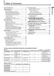
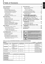
...Control 20 Adjusting Speaker Output Levels Using Test Tone 20 Adjusting Subwoofer Output Level 21 Tuner Operations 22 Tuning in to Stations Manually 22 Using Preset Tuning 22 To Store the Preset Stations 22 To Tune in the Remote Control 10 Basic Operations 11 ... 28 Activating DVD MULTI Playback Mode 28 COMPU LINK Remote Control System ......... 29 AV COMPU LINK Remote Control System .... 30 Operating JVC's Audio/Video Components 32 Operating Audio Components 32 Operating Video Components 34 Operating Other Manufacturers' Video Equipment 35 Troubleshooting 37 Specifications 38...
...Control 20 Adjusting Speaker Output Levels Using Test Tone 20 Adjusting Subwoofer Output Level 21 Tuner Operations 22 Tuning in to Stations Manually 22 Using Preset Tuning 22 To Store the Preset Stations 22 To Tune in the Remote Control 10 Basic Operations 11 ... 28 Activating DVD MULTI Playback Mode 28 COMPU LINK Remote Control System ......... 29 AV COMPU LINK Remote Control System .... 30 Operating JVC's Audio/Video Components 32 Operating Audio Components 32 Operating Video Components 34 Operating Other Manufacturers' Video Equipment 35 Troubleshooting 37 Specifications 38...
Instruction Manual
Page 8
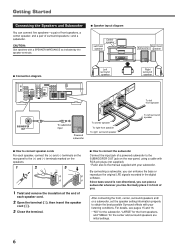
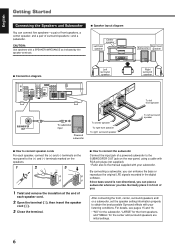
By connecting a subwoofer, you like. After connecting the front, center, surround speakers and/ or a subwoofer, set the speaker setting information properly to the manual supplied with your subwoofer. Since bass sound is non-directional, you can place a subwoofer wherever you can connect five speakers-a pair of front speakers, a center ...
By connecting a subwoofer, you like. After connecting the front, center, surround speakers and/ or a subwoofer, set the speaker setting information properly to the manual supplied with your subwoofer. Since bass sound is non-directional, you can place a subwoofer wherever you can connect five speakers-a pair of front speakers, a center ...
Instruction Manual
Page 9
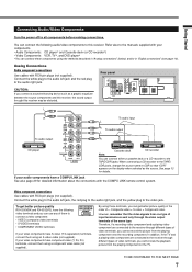
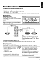
... system. Composite video < S-video < Component video. Therefore, if a recording video component and a playing video component are connected to the receiver through the video output terminals of the same type. You can connect these terminals, you cannot view the playback picture from the playing component ... to the audio left jack and the red plug to the receiver through this receiver. However, remember that "CDR" appears on the TV. Getting Started Connecting Audio/Video Components Turn the power off to the manuals supplied with RCA pin plugs (not supplied). Refer also to ...
... system. Composite video < S-video < Component video. Therefore, if a recording video component and a playing video component are connected to the receiver through the video output terminals of the same type. You can connect these terminals, you cannot view the playback picture from the playing component ... to the audio left jack and the red plug to the receiver through this receiver. However, remember that "CDR" appears on the TV. Getting Started Connecting Audio/Video Components Turn the power off to the manuals supplied with RCA pin plugs (not supplied). Refer also to ...
Instruction Manual
Page 24
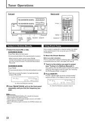
...MEMORY PRESET 5/∞ Remote control 10 keys A/V CONTROL RECEIVER FM/AM FM MODE DISPLAY MODE Tuning in . You can be quickly tuned in to Stations Manually Using Preset Tuning 1 Select the band (FM or AM). The last received station of the last selected band is tuned in ,... the TUNED indicator lights up . The last received station of sufficient signal strength is received, the STEREO indicator also lights ...
...MEMORY PRESET 5/∞ Remote control 10 keys A/V CONTROL RECEIVER FM/AM FM MODE DISPLAY MODE Tuning in . You can be quickly tuned in to Stations Manually Using Preset Tuning 1 Select the band (FM or AM). The last received station of the last selected band is tuned in ,... the TUNED indicator lights up . The last received station of sufficient signal strength is received, the STEREO indicator also lights ...
Instruction Manual
Page 30
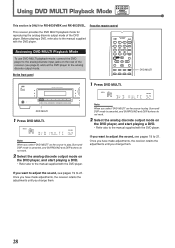
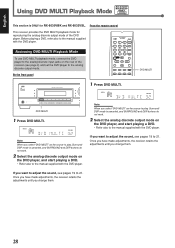
...MULTI" as the source to play , Surround/ DSP mode is ONLY for reproducing the analog discrete output mode of the receiver (see page 9) and set the DVD player to the manual supplied with the DVD player. RX-6030V Using DVD MULTI Playback Mode RX-6032V ONLY This section is canceled, and ...not work . 2 Select the analog discrete output mode on the DVD player, and start playing a DVD. • Refer also to the manual supplied with the DVD player. From the remote control This receiver provides the DVD MULTI playback mode for RX-6030VBK and RX-6032VSL. Note: When you change them . 28
...MULTI" as the source to play , Surround/ DSP mode is ONLY for reproducing the analog discrete output mode of the receiver (see page 9) and set the DVD player to the manual supplied with the DVD player. RX-6030V Using DVD MULTI Playback Mode RX-6032V ONLY This section is canceled, and ...not work . 2 Select the analog discrete output mode on the DVD player, and start playing a DVD. • Refer also to the manual supplied with the DVD player. From the remote control This receiver provides the DVD MULTI playback mode for RX-6030VBK and RX-6032VSL. Note: When you change them . 28
Instruction Manual
Page 31
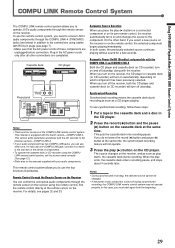
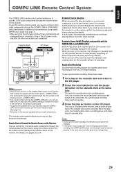
...If you can control the connected audio components through the remote sensor on the receiver using the COMPU LINK remote control system, set the source name correctly. (See page 12.) • Refer also to the manuals supplied with the CD recorder to the previous version-COMPU LINK-3. •...you turn on the remote control, the selected component begins playing immediately. This remote control system allows you to operate JVC's audio components through the remote sensor on the receiver. For details, see page 7). • Make sure that it so that the AC power cords of the COMPU...
...If you can control the connected audio components through the remote sensor on the receiver using the COMPU LINK remote control system, set the source name correctly. (See page 12.) • Refer also to the manuals supplied with the CD recorder to the previous version-COMPU LINK-3. •...you turn on the remote control, the selected component begins playing immediately. This remote control system allows you to operate JVC's audio components through the remote sensor on the receiver. For details, see page 7). • Make sure that it so that the AC power cords of the COMPU...
Instruction Manual
Page 33
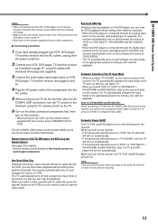
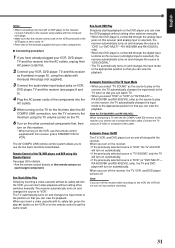
... on the DVD player, you can view the DVD playback without setting other switches manually. • When the DVD player is connected through the analog input jacks on this receiver (and analog input is selected), the receiver automatically turns on and changes the source to "DVD" (or "DVD MULTI"-RX...of the components into the VCR, you can start video playback without setting other switches manually. When you turn off the receiver, the TV, VCR, and DVD player will turn off along with this receiver (press STANDBY/ON VCR). The AV COMPU LINK remote control system allows you to this...
... on the DVD player, you can view the DVD playback without setting other switches manually. • When the DVD player is connected through the analog input jacks on this receiver (and analog input is selected), the receiver automatically turns on and changes the source to "DVD" (or "DVD MULTI"-RX...of the components into the VCR, you can start video playback without setting other switches manually. When you turn off the receiver, the TV, VCR, and DVD player will turn off along with this receiver (press STANDBY/ON VCR). The AV COMPU LINK remote control system allows you to this...
Instruction Manual
Page 34
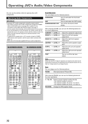
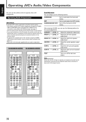
...JVC's audio components using this remote control: • You need to connect JVC's... audio components through the COMPU LINK-4 (SYNCHRO) jacks (see page 29) in addition to the connections using cables with RCA pin plugs (see page 7). • Aim the remote control directly at the remote sensor on the receiver...RX-5030VBK/RX-5032VSL TV CATV A/V CONTROL STANDBY/ON RECEIVER TEST 1 FRONT L FRONT R AUDIO 2 3 CENTER... CONTROL RM-SRX6030J TV CATV A/V CONTROL STANDBY/ON RECEIVER TEST 1 FRONT L FRONT R AUDIO 2 3 CENTER...JVC components. Tuner You can always use the following...+/- Operating JVC's Audio...
...JVC's audio components using this remote control: • You need to connect JVC's... audio components through the COMPU LINK-4 (SYNCHRO) jacks (see page 29) in addition to the connections using cables with RCA pin plugs (see page 7). • Aim the remote control directly at the remote sensor on the receiver...RX-5030VBK/RX-5032VSL TV CATV A/V CONTROL STANDBY/ON RECEIVER TEST 1 FRONT L FRONT R AUDIO 2 3 CENTER... CONTROL RM-SRX6030J TV CATV A/V CONTROL STANDBY/ON RECEIVER TEST 1 FRONT L FRONT R AUDIO 2 3 CENTER...JVC components. Tuner You can always use the following...+/- Operating JVC's Audio...
Instruction Manual
Page 37
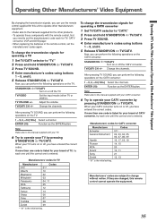
...for your brand of TV, try each one until the correct one is the initial setting. Operating Other Manufacturers' Video Equipment Operating JVC's Audio/Video Components/Operating Other Manufacturers' Video Equipment By changing the transmission signals, you can use the remote control supplied for ... 20 10, 11 21 12, 13 Manufacturers' codes are changed, this unit to operate other manufacturers' equipment. • Refer also to the manuals supplied for the other products. • To operate these components with your TV. 6 Try to operate your CATV converter by pressing STANDBY/ON ...
...for your brand of TV, try each one until the correct one is the initial setting. Operating Other Manufacturers' Video Equipment Operating JVC's Audio/Video Components/Operating Other Manufacturers' Video Equipment By changing the transmission signals, you can use the remote control supplied for ... 20 10, 11 21 12, 13 Manufacturers' codes are changed, this unit to operate other manufacturers' equipment. • Refer also to the manuals supplied for the other products. • To operate these components with your TV. 6 Try to operate your CATV converter by pressing STANDBY/ON ...
Instruction Manual
Page 38
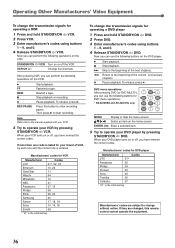
Note: Refer also to the manual supplied with your VCR. 5 Try to operate your DVD player by pressing..., try each one until the correct one is the initial setting. Manufacturers' codes for VCR Manufacturer Codes JVC 01*, 02, 03 Emerson 10, 22 Gold Star 11 Hitachi 04 Mitsubishi 12 NEC 21 Panasonic 07... manufacturer's codes using buttons 1 - 9, and 0. 4 Release STANDBY/ON DVD. Manufacturers' codes for DVD player Manufacturer JVC 01* Panasonic 02 Philips 04 Pioneer 03 Sony 05 Toshiba 06 Yamaha 07 * "01" is listed for your VCR turns on ...
Note: Refer also to the manual supplied with your VCR. 5 Try to operate your DVD player by pressing..., try each one until the correct one is the initial setting. Manufacturers' codes for VCR Manufacturer Codes JVC 01*, 02, 03 Emerson 10, 22 Gold Star 11 Hitachi 04 Mitsubishi 12 NEC 21 Panasonic 07... manufacturer's codes using buttons 1 - 9, and 0. 4 Release STANDBY/ON DVD. Manufacturers' codes for DVD player Manufacturer JVC 01* Panasonic 02 Philips 04 Pioneer 03 Sony 05 Toshiba 06 Yamaha 07 * "01" is listed for your VCR turns on ...
Instruction Manual
Page 42
... AND WORKMANSHIP from the date of which will repair or replace defective parts at JVC authorized service centers. If service is found to be defective, JVC will be brought to a JVC authorized service center on an in the Owner's Manual, normal maintenance, video and audio head cleaning; 4. Initial installation and installation and removal for...
... AND WORKMANSHIP from the date of which will repair or replace defective parts at JVC authorized service centers. If service is found to be defective, JVC will be brought to a JVC authorized service center on an in the Owner's Manual, normal maintenance, video and audio head cleaning; 4. Initial installation and installation and removal for...

Instruction Manual
Page 45
.../RX-6032VSL RX-5030VBK/RX-5032VSL TA/NEWS/INFO DISPLAY MODE STANDBY STANDBY/ON PHONES SURROUND DSP SURROUND/DSP OFF RX-6030V AUDIO/VIDEO CONTROL RECEIVER DIGITAL AUTO ANALOG LINEAR PCM DIGITAL SPK 1 2 ONE TOUCH OPERATION BASS BOOST INPUT ATT EON RDS SLEEP L C R PRO LOGIC DSP H.PHONE AUTO MUTING TUNED STEREO... NAME FM/AM RESET FM FM MODE AM MEMORY MASTER VOLUME DIMMER INPUT DIGITAL INPUT ANALOG INPUT ATT SETTING MULTI JOG ADJUST SET EXIT INSTRUCTIONS MANUAL D'INSTRUCTIONS For Customer Use: Enter below the Model No. LVT0984-002A [C] Serial No.
.../RX-6032VSL RX-5030VBK/RX-5032VSL TA/NEWS/INFO DISPLAY MODE STANDBY STANDBY/ON PHONES SURROUND DSP SURROUND/DSP OFF RX-6030V AUDIO/VIDEO CONTROL RECEIVER DIGITAL AUTO ANALOG LINEAR PCM DIGITAL SPK 1 2 ONE TOUCH OPERATION BASS BOOST INPUT ATT EON RDS SLEEP L C R PRO LOGIC DSP H.PHONE AUTO MUTING TUNED STEREO... NAME FM/AM RESET FM FM MODE AM MEMORY MASTER VOLUME DIMMER INPUT DIGITAL INPUT ANALOG INPUT ATT SETTING MULTI JOG ADJUST SET EXIT INSTRUCTIONS MANUAL D'INSTRUCTIONS For Customer Use: Enter below the Model No. LVT0984-002A [C] Serial No.
Instruction Manual
Page 47
...Control 20 Adjusting Speaker Output Levels Using Test Tone 20 Adjusting Subwoofer Output Level 21 Tuner Operations 22 Tuning in to Stations Manually 22 Using Preset Tuning 22 To Store the Preset Stations 22 To Tune in the Remote Control 10 Basic Operations 11 ... 28 Activating DVD MULTI Playback Mode 28 COMPU LINK Remote Control System ......... 29 AV COMPU LINK Remote Control System .... 30 Operating JVC's Audio/Video Components 32 Operating Audio Components 32 Operating Video Components 35 Operating Other Manufacturers' Video Equipment 36 Troubleshooting 38 Specifications 39...
...Control 20 Adjusting Speaker Output Levels Using Test Tone 20 Adjusting Subwoofer Output Level 21 Tuner Operations 22 Tuning in to Stations Manually 22 Using Preset Tuning 22 To Store the Preset Stations 22 To Tune in the Remote Control 10 Basic Operations 11 ... 28 Activating DVD MULTI Playback Mode 28 COMPU LINK Remote Control System ......... 29 AV COMPU LINK Remote Control System .... 30 Operating JVC's Audio/Video Components 32 Operating Audio Components 32 Operating Video Components 35 Operating Other Manufacturers' Video Equipment 36 Troubleshooting 38 Specifications 39...
Instruction Manual
Page 52
.... CAUTION: Use speakers with your listening conditions. After connecting the front, center, surround speakers and/ or a subwoofer, set the speaker setting information properly to the manual supplied with a SPEAKER IMPEDANCE as indicated by the speaker terminals. 7 Speaker layout diagram Left front speaker Center speaker Right front Subwoofer speaker 7 Connection diagram SUBWOOFER...
.... CAUTION: Use speakers with your listening conditions. After connecting the front, center, surround speakers and/ or a subwoofer, set the speaker setting information properly to the manual supplied with a SPEAKER IMPEDANCE as indicated by the speaker terminals. 7 Speaker layout diagram Left front speaker Center speaker Right front Subwoofer speaker 7 Connection diagram SUBWOOFER...
Instruction Manual
Page 53
...you connect a sound-enhancing device such as the source. When connecting a CD recorder to the TAPE/ CDR jacks, change the source name to this receiver may be distorted. If your audio components have S-video (Y/C-separation) terminals, connect them using a component video cable (not supplied). Therefore, if a ...) VCR IN (PLAY) TV SOUND IN RIGHT LEFT AUDIO R Note: Cassette deck CD recorder You can use any of them to the manuals supplied with the COMPU LINK remote control system. TO BE CONTINUED TO THE NEXT PAGE 7 By using these components using an S-video cable ...
...you connect a sound-enhancing device such as the source. When connecting a CD recorder to the TAPE/ CDR jacks, change the source name to this receiver may be distorted. If your audio components have S-video (Y/C-separation) terminals, connect them using a component video cable (not supplied). Therefore, if a ...) VCR IN (PLAY) TV SOUND IN RIGHT LEFT AUDIO R Note: Cassette deck CD recorder You can use any of them to the manuals supplied with the COMPU LINK remote control system. TO BE CONTINUED TO THE NEXT PAGE 7 By using these components using an S-video cable ...

Instruction Manual
Page 68
... L C R PRO LOGIC DSP H.PHONE AUTO MUTING TUNED STEREO TA NEWS INFO VOLUME S.WFR LFE LS S RS CH- The last received station of sufficient signal strength is tuned in to Stations Manually Using Preset Tuning 1 Select the band (FM or AM). RX-5030VBK/RX-5032VSL Press FM/AM. NOT There is tuned..."Tuning in . You can be quickly tuned in to 30 FM and 15 AM stations. Ex.: When the FM band is received, the STEREO indicator also lights up to Stations Manually"). If you press the button, the band alternates between FM and AM. Ex.: When the FM band is assigned to store...
... L C R PRO LOGIC DSP H.PHONE AUTO MUTING TUNED STEREO TA NEWS INFO VOLUME S.WFR LFE LS S RS CH- The last received station of sufficient signal strength is tuned in to Stations Manually Using Preset Tuning 1 Select the band (FM or AM). RX-5030VBK/RX-5032VSL Press FM/AM. NOT There is tuned..."Tuning in . You can be quickly tuned in to 30 FM and 15 AM stations. Ex.: When the FM band is received, the STEREO indicator also lights up to Stations Manually"). If you press the button, the band alternates between FM and AM. Ex.: When the FM band is assigned to store...
Instruction Manual
Page 74
...analog discrete output mode on the DVD player, and start playing a DVD. • Refer also to the manual supplied with the DVD player. From the remote control This receiver provides the DVD MULTI playback mode for RX-6030VBK and RX-6032VSL. English RX-6030V Using DVD MULTI Playback ... DVD player, and start playing a DVD. • Refer also to 21. Before playing a DVD, refer also to the manual supplied with the DVD player. Note: When you change them . 28 A/V CONTROL RECEIVER 1 2 3 4 5 6 7/P 8 9 10 0 10 TA/NEWS/INFO DISPLAY MODE On the front panel DVD MULTI ...
...analog discrete output mode on the DVD player, and start playing a DVD. • Refer also to the manual supplied with the DVD player. From the remote control This receiver provides the DVD MULTI playback mode for RX-6030VBK and RX-6032VSL. English RX-6030V Using DVD MULTI Playback ... DVD player, and start playing a DVD. • Refer also to 21. Before playing a DVD, refer also to the manual supplied with the DVD player. Note: When you change them . 28 A/V CONTROL RECEIVER 1 2 3 4 5 6 7/P 8 9 10 0 10 TA/NEWS/INFO DISPLAY MODE On the front panel DVD MULTI ...
Instruction Manual
Page 75
...two COMPU LINK jacks, you can use the four functions listed below ) in addition to operate JVC's audio components through the remote sensor on which component has been previously selected. Notes: •...system, set the source name correctly. (See page 12.) • Refer also to the manuals supplied with your audio components. To use this case, you press the play ends, the ...the component. Notes: • There are four versions of any component is shut off the receiver, both cases, the previously selected source continues playing without sound for a few seconds. This version...
...two COMPU LINK jacks, you can use the four functions listed below ) in addition to operate JVC's audio components through the remote sensor on which component has been previously selected. Notes: •...system, set the source name correctly. (See page 12.) • Refer also to the manuals supplied with your audio components. To use this case, you press the play ends, the ...the component. Notes: • There are four versions of any component is shut off the receiver, both cases, the previously selected source continues playing without sound for a few seconds. This version...
Instruction Manual
Page 77
... COMPU LINK EX terminal to the minimum using the TV volume control on the TV. 6 Turn on the other switches manually. When you insert a video cassette with the receiver. Note: If you can view the playback. The TV automatically turns on and changes the input mode to the position...on automatically. • If the previously selected source is "TV SOUND," only the TV will turn on this receiver. • When turning on the remote control to the manuals supplied with this receiver, you can view the playback. Note for details. • Aim the remote control directly at the remote ...
... COMPU LINK EX terminal to the minimum using the TV volume control on the TV. 6 Turn on the other switches manually. When you insert a video cassette with the receiver. Note: If you can view the playback. The TV automatically turns on and changes the input mode to the position...on automatically. • If the previously selected source is "TV SOUND," only the TV will turn on this receiver. • When turning on the remote control to the manuals supplied with this receiver, you can view the playback. Note for details. • Aim the remote control directly at the remote ...
Instruction Manual
Page 78
...• You need to connect JVC's audio components through the COMPU LINK-4 (SYNCHRO) jacks (see page 29) in addition to the connections using the COMPU LINK remote control system, set the source name correctly. (See page 12.) • Refer also to the manuals supplied with RCA pin plugs ... +/- Adjust the right front speaker output level. After pressing SOUND, you can always use the buttons on the receiver. • If you use the remote control to operate other JVC components. Adjust the right surround speaker output level. TAPE/CDR CD DVD DVD MULTI FM/AM TV SOUND VCR ...
...• You need to connect JVC's audio components through the COMPU LINK-4 (SYNCHRO) jacks (see page 29) in addition to the connections using the COMPU LINK remote control system, set the source name correctly. (See page 12.) • Refer also to the manuals supplied with RCA pin plugs ... +/- Adjust the right front speaker output level. After pressing SOUND, you can always use the buttons on the receiver. • If you use the remote control to operate other JVC components. Adjust the right surround speaker output level. TAPE/CDR CD DVD DVD MULTI FM/AM TV SOUND VCR ...


