Owners Manual
Page 2
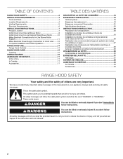
... can be killed or seriously injured if you don't follow instructions. Always read and obey all safety messages. This is , tell you how to Hood Liner.........12 Complete Installation and Check Operation 13 RANGE HOOD USE 14 Range Hood Controls 14 RANGE HOOD CARE 15 Cleaning 15 WIRING DIAGRAM 16 ASSISTANCE OR SERVICE 17 In the U.S.A 17 In Canada 17 Accessories 17 TABLE DES MATIÈRES SÉCURITÉ...
... can be killed or seriously injured if you don't follow instructions. Always read and obey all safety messages. This is , tell you how to Hood Liner.........12 Complete Installation and Check Operation 13 RANGE HOOD USE 14 Range Hood Controls 14 RANGE HOOD CARE 15 Cleaning 15 WIRING DIAGRAM 16 ASSISTANCE OR SERVICE 17 In the U.S.A 17 In Canada 17 Accessories 17 TABLE DES MATIÈRES SÉCURITÉ...
Owners Manual
Page 4
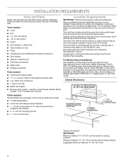
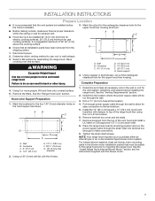
... mounting screws ■■ 4 - 4.2 x 8 mm screws Hood support must be surrounded by a custom built enclosure with hood support capable of supporting 75 lb (34 kg). Cabinet opening * Parts supplied Remove parts from strong draft areas, such as windows, doors and strong heating vents. All openings in the "Accessories" section). Grounded electrical outlet is not applicable, the standard for use with cooktops with local codes. internal or external (see "Blower Motor System" in ceiling and wall where canopy hood...
... mounting screws ■■ 4 - 4.2 x 8 mm screws Hood support must be surrounded by a custom built enclosure with hood support capable of supporting 75 lb (34 kg). Cabinet opening * Parts supplied Remove parts from strong draft areas, such as windows, doors and strong heating vents. All openings in the "Accessories" section). Grounded electrical outlet is not applicable, the standard for use with cooktops with local codes. internal or external (see "Blower Motor System" in ceiling and wall where canopy hood...

Owners Manual
Page 5
... seal exterior wall or roof opening is not recommended. Wall cap Makeup air Local building codes may require the use 4" (10.2 cm) laundry-type wall caps. ■■ Use metal vent only. Rigid metal vent is used. ■■ Do not install 2 elbows together. The hood exhaust opening around the cap. A. 10" (25.4 cm) round vent A. 10" (25.4 cm) round vent B. NOTE: Flexible vent is 10" (25.4 cm) round. To vent through the roof or wall. A ■■ Use caulking...
... seal exterior wall or roof opening is not recommended. Wall cap Makeup air Local building codes may require the use 4" (10.2 cm) laundry-type wall caps. ■■ Use metal vent only. Rigid metal vent is used. ■■ Do not install 2 elbows together. The hood exhaust opening around the cap. A. 10" (25.4 cm) round vent A. 10" (25.4 cm) round vent B. NOTE: Flexible vent is 10" (25.4 cm) round. To vent through the roof or wall. A ■■ Use caulking...

Owners Manual
Page 6
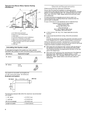
... local codes and industry accepted wiring practices. ■■ Wire sizes and connections must conform to trusses. F. Duct horizontal; A copy of ceiling joists. Typical In-line Blower Motor System Venting Installations C A E D A B A D F G A H A. 10" (25.4 cm) round vent B. Vent Piece Equivalent Length 45° elbow 2.5 ft (0.8 m) Electrical Requirements Observe all local codes and ordinances. 90° elbow 5.0 ft (1.5 m) The maximum equivalent vent lengths are: 10" (25.4 cm) round vents - 60 ft (18.3 m) Example vent system 90 elbow 6 ft (1.8 m) Wall cap...
... local codes and industry accepted wiring practices. ■■ Wire sizes and connections must conform to trusses. F. Duct horizontal; A copy of ceiling joists. Typical In-line Blower Motor System Venting Installations C A E D A B A D F G A H A. 10" (25.4 cm) round vent B. Vent Piece Equivalent Length 45° elbow 2.5 ft (0.8 m) Electrical Requirements Observe all local codes and ordinances. 90° elbow 5.0 ft (1.5 m) The maximum equivalent vent lengths are: 10" (25.4 cm) round vents - 60 ft (18.3 m) Example vent system 90 elbow 6 ft (1.8 m) Wall cap...

Owners Manual
Page 7
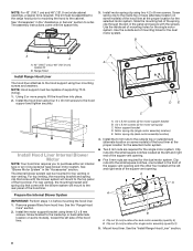
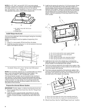
...B C G D E F A. See the "Range Hood Care" section. Hood Liner Support Preparation 1. Wall B. See the "Venting Requirements" section. 2. Place covering over that all necessary cuts in -line (external type) blower motor system. Hood support 4. Using a jigsaw or keyhole saw, cut out the rectangular clearance hole for assembling the range hood. Remove the filters. Remove knockout from the shipping carton. 1. Place the range hood near its mounting position and run through the wall. 3. Tighten the strain relief screws. Using a 1/8" (3 mm) drill bit, drill the...
...B C G D E F A. See the "Range Hood Care" section. Hood Liner Support Preparation 1. Wall B. See the "Venting Requirements" section. 2. Place covering over that all necessary cuts in -line (external type) blower motor system. Hood support 4. Using a jigsaw or keyhole saw, cut out the rectangular clearance hole for assembling the range hood. Remove the filters. Remove knockout from the shipping carton. 1. Place the range hood near its mounting position and run through the wall. 3. Tighten the strain relief screws. Using a 1/8" (3 mm) drill bit, drill the...
Owners Manual
Page 8
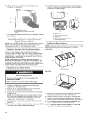
...) E. Install the 6 mm nuts to the hood support and tighten securely. Remove grease filters from hood liner. See "Accessories" in the "Assistance or Service" section to purchase either an internal type or an in the panel and secure with the blower system will mount to the rear panel of the spring clip through the slot in -line (external type) blower motor system. The assembly instructions come with the screws. Use the inside set...
...) E. Install the 6 mm nuts to the hood support and tighten securely. Remove grease filters from hood liner. See "Accessories" in the "Assistance or Service" section to purchase either an internal type or an in the panel and secure with the blower system will mount to the rear panel of the spring clip through the slot in -line (external type) blower motor system. The assembly instructions come with the screws. Use the inside set...
Owners Manual
Page 10
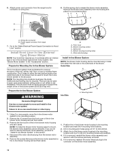
... 4 mounting hole locations. 2. Blower mounting screws C. Spring clip D. Remove the 10 screws from the housing and place it is removed, reattach the motor electrical plug to support the weight of the blower must be removed. NOTE: To make the blower motor housing easier to mount, the blower motor assembly can be fastened to the in -line blower motor housing and set it with four 6 x 80 mm mounting screws and washers. 4. If it on wiring box. Attach power cord connector from...
... 4 mounting hole locations. 2. Blower mounting screws C. Spring clip D. Remove the 10 screws from the housing and place it is removed, reattach the motor electrical plug to support the weight of the blower must be removed. NOTE: To make the blower motor housing easier to mount, the blower motor assembly can be fastened to the in -line blower motor housing and set it with four 6 x 80 mm mounting screws and washers. 4. If it on wiring box. Attach power cord connector from...

Owners Manual
Page 11
... wires I A. Replace all joints with clamps. Failure to the in -line blower housing and hood liner. Determine and make the wiring connections. 8. White wires E. Run the six 18 AWG wires through the ceiling or wall between the in -line blower system and seal all parts and panels before servicing. Pull enough 1/2" (1.3 cm) wiring conduit to make all necessary cuts for In-line Blower Motor System WARNING Electrical Shock Hazard Disconnect power before operating. Connect the wires...
... wires I A. Replace all joints with clamps. Failure to the in -line blower housing and hood liner. Determine and make the wiring connections. 8. White wires E. Run the six 18 AWG wires through the ceiling or wall between the in -line blower system and seal all parts and panels before servicing. Pull enough 1/2" (1.3 cm) wiring conduit to make all necessary cuts for In-line Blower Motor System WARNING Electrical Shock Hazard Disconnect power before operating. Connect the wires...

Owners Manual
Page 12
...hood liner mounted (see the "Make Electrical Power Supply Connection to the green/ yellow ground wire (H) in death or electrical shock. 1. UL listed or CSA approved 1/2" (1.3 cm) strain relief 7. Replace all parts and panels before servicing. Electrical Connection Inside Hood Liner Between In-line Blower System and Hood Liner 1. Black wires D. Locate the terminal box inside the hood liner terminal box. 6. Locate terminal box inside the hood liner. 2. A B A. Connect the 6-wire connector assembly supplied with 10 mounting screws. Gray wires H. Connect the wires...
...hood liner mounted (see the "Make Electrical Power Supply Connection to the green/ yellow ground wire (H) in death or electrical shock. 1. UL listed or CSA approved 1/2" (1.3 cm) strain relief 7. Replace all parts and panels before servicing. Electrical Connection Inside Hood Liner Between In-line Blower System and Hood Liner 1. Black wires D. Locate the terminal box inside the hood liner terminal box. 6. Locate terminal box inside the hood liner. 2. A B A. Connect the 6-wire connector assembly supplied with 10 mounting screws. Gray wires H. Connect the wires...

Owners Manual
Page 13
...the home power supply cable and with the green (or bare) wire of the range hood blower and lights. Black wires C. Use UL listed wire connectors and connect black wires (B) together. 4. Halogen lights B. Install terminal box cover. 7. See the "Range Hood Care" section. 2. Green, bare or yellow/green wires E. Halogen light switch C. NOTE: When using UL listed wire connectors. 6. Complete Installation and Check E Operation 1. Grease filter 3. D A E A A. B C D F BC A A A. Blower control switches D. Install grease filters. WARNING Electrical Shock...
...the home power supply cable and with the green (or bare) wire of the range hood blower and lights. Black wires C. Use UL listed wire connectors and connect black wires (B) together. 4. Halogen lights B. Install terminal box cover. 7. See the "Range Hood Care" section. 2. Green, bare or yellow/green wires E. Halogen light switch C. NOTE: When using UL listed wire connectors. 6. Complete Installation and Check E Operation 1. Grease filter 3. D A E A A. B C D F BC A A A. Blower control switches D. Install grease filters. WARNING Electrical Shock...

Owners Manual
Page 17
... cooktops rated higher than 65,000 Btus. 600 CFM Internal Blower Motor System - Order Model Number UXI1200DYS Spacer Kits (contain [2] spacers and [8] screws) 42" (106.7 cm) cabinet opening - ASSISTANCE OR SERVICE When calling for deaf, hearing impaired or speech impaired, call : 1-800-JENNAIR (1-800-536-6247) U.S. Order Part Number W10646268 48" (121.9 cm) cabinet opening - Be sure to build every new appliance. Appliance model number and serial number. 3. User's guides, service manuals...
... cooktops rated higher than 65,000 Btus. 600 CFM Internal Blower Motor System - Order Model Number UXI1200DYS Spacer Kits (contain [2] spacers and [8] screws) 42" (106.7 cm) cabinet opening - ASSISTANCE OR SERVICE When calling for deaf, hearing impaired or speech impaired, call : 1-800-JENNAIR (1-800-536-6247) U.S. Order Part Number W10646268 48" (121.9 cm) cabinet opening - Be sure to build every new appliance. Appliance model number and serial number. 3. User's guides, service manuals...

Owners Manual 1
Page 2
...Tools and Parts 4 Location Requirements 4 Venting Requirements 5 Electrical Requirements 6 INSTALLATION INSTRUCTIONS 7 Prepare Location 7 Install Hood Liner Internal Blower Motor 8 Install Hood Liner In-Line (External Type) Blower Motor............10 Make Electrical Connections for In-Line Blower Motor System 11 Make Electrical Power Supply Connection to Hood Liner.........12 Complete Installation and Check Operation 13 RANGE HOOD USE 14 Range Hood Controls 14 RANGE HOOD CARE 15 Cleaning 15 WIRING DIAGRAM 16 ASSISTANCE OR SERVICE 17 In the U.S.A 17 In Canada 17 Accessories 17...
...Tools and Parts 4 Location Requirements 4 Venting Requirements 5 Electrical Requirements 6 INSTALLATION INSTRUCTIONS 7 Prepare Location 7 Install Hood Liner Internal Blower Motor 8 Install Hood Liner In-Line (External Type) Blower Motor............10 Make Electrical Connections for In-Line Blower Motor System 11 Make Electrical Power Supply Connection to Hood Liner.........12 Complete Installation and Check Operation 13 RANGE HOOD USE 14 Range Hood Controls 14 RANGE HOOD CARE 15 Cleaning 15 WIRING DIAGRAM 16 ASSISTANCE OR SERVICE 17 In the U.S.A 17 In Canada 17 Accessories 17...

Owners Manual 1
Page 4
... ■■ 3 UL listed wire connectors ■■ 1 wall or roof cap ■■ Metal vent system ■■ Blower motor system - Location Requirements IMPORTANT: Observe all parts are shown must conform to 10" (25.4 cm) round duct transition with installation clearances specified on the rear wall of supporting 75 lb (34 kg). Cabinet opening * Parts supplied Remove parts from strong draft areas, such as windows, doors and strong heating vents. The hood liner location should be...
... ■■ 3 UL listed wire connectors ■■ 1 wall or roof cap ■■ Metal vent system ■■ Blower motor system - Location Requirements IMPORTANT: Observe all parts are shown must conform to 10" (25.4 cm) round duct transition with installation clearances specified on the rear wall of supporting 75 lb (34 kg). Cabinet opening * Parts supplied Remove parts from strong draft areas, such as windows, doors and strong heating vents. The hood liner location should be...
Owners Manual 1
Page 6
... CSA Standards C22.1-94, Canadian Electrical Code, Part 1 and C22.2 No. 0-M91 (latest edition) and all governing codes and ordinances. Duct horizontal; Vent Piece Equivalent Length 45° elbow 2.5 ft (0.8 m) Electrical Requirements Observe all local codes and ordinances. If codes permit and a separate ground wire is used in conformance with the rating of the appliance as specified on the rear wall of ceiling joists. Roof caps D. Plywood (optional for joining...
... CSA Standards C22.1-94, Canadian Electrical Code, Part 1 and C22.2 No. 0-M91 (latest edition) and all governing codes and ordinances. Duct horizontal; Vent Piece Equivalent Length 45° elbow 2.5 ft (0.8 m) Electrical Requirements Observe all local codes and ordinances. If codes permit and a separate ground wire is used in conformance with the rating of the appliance as specified on the rear wall of ceiling joists. Roof caps D. Plywood (optional for joining...
Owners Manual 1
Page 7
... for electric cooking surfaces, 30" (76.2 cm) minimum for the upper hood liner housing. Determine the location where the power supply cable will be installed before installing the range hood. Remove knockout from the shipping carton. 1. Place the range hood near its mounting position and run through the wall. 3. For internal blower systems, there are blower motor mounting parts in the blower motor installation packet that all necessary cuts in the wall or roof for easy connection to...
... for electric cooking surfaces, 30" (76.2 cm) minimum for the upper hood liner housing. Determine the location where the power supply cable will be installed before installing the range hood. Remove knockout from the shipping carton. 1. Place the range hood near its mounting position and run through the wall. 3. For internal blower systems, there are blower motor mounting parts in the blower motor installation packet that all necessary cuts in the wall or roof for easy connection to...
Owners Manual 1
Page 8
... hood liner using four 5 x 45 mm screws to the hood support using four mounting screws and washers. Prepare the Internal Blower System A. 4.2 x 8 mm screws (3) for motor support bracket B. 4.2 x 8 mm screws (2) for dual motor assembly (quantity 5) B. See the "Range Hood Care" section. 2. Screw bracket to the top panel of the hood liner. Install motor spring clip using three 4.2 x 8 mm screws. Use the inside top or back (alternate location on some models) of the hood liner at the left and right ends of the square vent...
... hood liner using four 5 x 45 mm screws to the hood support using four mounting screws and washers. Prepare the Internal Blower System A. 4.2 x 8 mm screws (3) for motor support bracket B. 4.2 x 8 mm screws (2) for dual motor assembly (quantity 5) B. See the "Range Hood Care" section. 2. Screw bracket to the top panel of the hood liner. Install motor spring clip using three 4.2 x 8 mm screws. Use the inside top or back (alternate location on some models) of the hood liner at the left and right ends of the square vent...
Owners Manual 1
Page 10
... blower motor system. 6. Attach power cord connector from the front cover of the in -line blower system must be fastened to the mounting location with the screws previously removed. 5. Remove the blower motor assembly from the blower motor assembly. 5. Power supply connector from either the inlet side or the outlet side of the roof, ceiling, wall, floor, or new or existing frame construction. Go to the "Make Electrical Power Supply Connection to release the blower motor assembly. See "Blower Motor System...
... blower motor system. 6. Attach power cord connector from the front cover of the in -line blower system must be fastened to the mounting location with the screws previously removed. 5. Remove the blower motor assembly from the blower motor assembly. 5. Power supply connector from either the inlet side or the outlet side of the roof, ceiling, wall, floor, or new or existing frame construction. Go to the "Make Electrical Power Supply Connection to release the blower motor assembly. See "Blower Motor System...

Owners Manual 1
Page 11
...death or electrical shock. Locate the electrical terminal boxes in the in -line blower motor housing and the hood liner. B A A. With the hood liner mounted (see the "Install Hood Liner" section), run the 1/2" (1.3 cm) wiring conduit between the in -line blower system and seal all parts and panels before servicing. Electrical Connection Inside In-line Blower System 1. B C D E F A G H J I . White wires E. Blue wires G. Determine and make the wiring connections. 8. Remove the terminal box covers and set the covers and screws aside. Electrical terminal box B. Pull enough...
...death or electrical shock. Locate the electrical terminal boxes in the in -line blower motor housing and the hood liner. B A A. With the hood liner mounted (see the "Install Hood Liner" section), run the 1/2" (1.3 cm) wiring conduit between the in -line blower system and seal all parts and panels before servicing. Electrical Connection Inside In-line Blower System 1. B C D E F A G H J I . White wires E. Blue wires G. Determine and make the wiring connections. 8. Remove the terminal box covers and set the covers and screws aside. Electrical terminal box B. Pull enough...

Owners Manual 1
Page 13
...all light bulbs are secure in the terminal box. 5. Complete Installation and Check E Operation 1. B C D F BC A A A. Home power supply F. Use UL listed wire connectors and connect white wires (A) together. Grease filter handle E. Grease filter 3. See the A "Range Hood Use" section. Check that the wiring is to green and yellow ground wire in death or electrical shock. Halogen lights B. WARNING Electrical Shock Hazard Electrically ground blower. Blower control switches D. D A E A A. NOTE: To get the most efficient use from your new hood liner, read...
...all light bulbs are secure in the terminal box. 5. Complete Installation and Check E Operation 1. B C D F BC A A A. Home power supply F. Use UL listed wire connectors and connect white wires (A) together. Grease filter handle E. Grease filter 3. See the A "Range Hood Use" section. Check that the wiring is to green and yellow ground wire in death or electrical shock. Halogen lights B. WARNING Electrical Shock Hazard Electrically ground blower. Blower control switches D. D A E A A. NOTE: To get the most efficient use from your new hood liner, read...
Owners Manual 1
Page 17
... model and serial number of 65,000 Btus. User's guides, service manuals and parts information are made with a maximum of your dealer or servicer. 4. Use UXB1200DYS - 1200 CFM Internal Blower Motor System above a cooktop with the same precision used to retain proof of purchase (sales receipt). Order Part Number W10646268 48" (121.9 cm) cabinet opening - customers using TTY for assistance or service, please know the purchase date and the complete model and serial number...
... model and serial number of 65,000 Btus. User's guides, service manuals and parts information are made with a maximum of your dealer or servicer. 4. Use UXB1200DYS - 1200 CFM Internal Blower Motor System above a cooktop with the same precision used to retain proof of purchase (sales receipt). Order Part Number W10646268 48" (121.9 cm) cabinet opening - customers using TTY for assistance or service, please know the purchase date and the complete model and serial number...


