
User Manual
Page 1
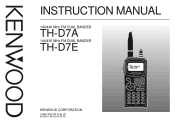
INSTRUCTION MANUAL 144/440 MHz FM DUAL BANDER TH-D7A 144/430 MHz FM DUAL BANDER TH-D7E STA CON PACKET96BCONDUP 57 9 KENWOOD CORPORATION © B62-1004-20 (K,E) (A) 09 08 07 06 05 04 03 02
INSTRUCTION MANUAL 144/440 MHz FM DUAL BANDER TH-D7A 144/430 MHz FM DUAL BANDER TH-D7E STA CON PACKET96BCONDUP 57 9 KENWOOD CORPORATION © B62-1004-20 (K,E) (A) 09 08 07 06 05 04 03 02
User Manual
Page 2
...KENWOOD FM Dual Bander. With a portable computer, allows you to enjoy Packet operation quite easily. • Includes a program for plug-and-play color slow-scan television (SSTV). • Utilizes Sky Command System 2 designed to purchase this manual. TH-D7A: 144/440 MHz FM Dual Bander (U.S.A./ Canada) TH-D7E... • Equipped with an easy-to make data communications much more convenient than before. KENWOOD believes that you decided to control a KENWOOD HF transceiver at a remote location (TH-D7A only). Allows each memory channel to be named using up to the AX.25 ...
...KENWOOD FM Dual Bander. With a portable computer, allows you to enjoy Packet operation quite easily. • Includes a program for plug-and-play color slow-scan television (SSTV). • Utilizes Sky Command System 2 designed to purchase this manual. TH-D7A: 144/440 MHz FM Dual Bander (U.S.A./ Canada) TH-D7E... • Equipped with an easy-to make data communications much more convenient than before. KENWOOD believes that you decided to control a KENWOOD HF transceiver at a remote location (TH-D7A only). Allows each memory channel to be named using up to the AX.25 ...

User Manual
Page 3
...The supply voltage must be determined by turning the equipment off and on, the user is encouraged to try to correct the interference by KENWOOD documentation. • When using a regulated power supply, connect the specified DC cable (option) to the DC IN jack on Ni...digital device, pursuant to Part 15 of direct sunlight nor place the transceiver close to provide reasonable protection against harmful interference in the instruction manual. These limits are expressly approved in a residential installation. Only): The RBRC Recycle seal found to comply with the instructions, may cause...
...The supply voltage must be determined by turning the equipment off and on, the user is encouraged to try to correct the interference by KENWOOD documentation. • When using a regulated power supply, connect the specified DC cable (option) to the DC IN jack on Ni...digital device, pursuant to Part 15 of direct sunlight nor place the transceiver close to provide reasonable protection against harmful interference in the instruction manual. These limits are expressly approved in a residential installation. Only): The RBRC Recycle seal found to comply with the instructions, may cause...

User Manual
Page 4
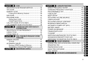
CONTENTS SUPPLIED ACCESSORIES 1 CONVENTIONS FOLLOWED IN THIS MANUAL ....... 1 CHAPTER 1 PREPARATION INSTALLING THE NiCd BATTERY PACK 2 CHARGING THE NiCd BATTERY PACK 2 INSTALLING THE ANTENNA 3 INSTALLING THE HAND STRAP/ BELT HOOK ......... 3 INSTALLING ALKALINE BATTERIES... REPEATER FREQUENCIES 27 STORING ODD-SPLIT REPEATER FREQUENCIES 27 RECALLING A MEMORY CHANNEL 28 CLEARING A MEMORY CHANNEL 28 NAMING A MEMORY CHANNEL 29 CALL CHANNEL (TH-D7A ONLY 30 Recalling the Call Channel 30 Reprogramming the Call Channel 30 MEMORY-TO-VFO TRANSFER 31 CHANNEL DISPLAY 31 PARTIAL OR FULL RESET...
CONTENTS SUPPLIED ACCESSORIES 1 CONVENTIONS FOLLOWED IN THIS MANUAL ....... 1 CHAPTER 1 PREPARATION INSTALLING THE NiCd BATTERY PACK 2 CHARGING THE NiCd BATTERY PACK 2 INSTALLING THE ANTENNA 3 INSTALLING THE HAND STRAP/ BELT HOOK ......... 3 INSTALLING ALKALINE BATTERIES... REPEATER FREQUENCIES 27 STORING ODD-SPLIT REPEATER FREQUENCIES 27 RECALLING A MEMORY CHANNEL 28 CLEARING A MEMORY CHANNEL 28 NAMING A MEMORY CHANNEL 29 CALL CHANNEL (TH-D7A ONLY 30 Recalling the Call Channel 30 Reprogramming the Call Channel 30 MEMORY-TO-VFO TRANSFER 31 CHANNEL DISPLAY 31 PARTIAL OR FULL RESET...
User Manual
Page 5
... ONLY 38 CALL/MEMORY SCAN (TH-D7A ONLY 38 CHAPTER 9 CONTINUOUS TONE CODED SQUELCH SYSTEM (CTCSS) SELECTING A CTCSS FREQUENCY 39 USING CTCSS 40 CTCSS FREQ. ID 40 CHAPTER 10 DUAL TONE MULTI-FREQUENCY (DTMF) FUNCTIONS MANUAL DIALING 41 TX Hold 41 AUTOMATIC DIALER 42 Storing a DTMF Number in Memory... 10 POWER-ON MESSAGE 50 11 TRANSCEIVER LOCK 50 12 TX INHIBIT 51 13 SWITCHING AM/FM MODE (TH-D7A ONLY 51 14 ADVANCED INTERCEPT POINT (AIP 51 15 SWITCHING TX DEVIATION (TH-D7E ONLY) ......... 51 16 CHAPTER 13 PACKET OPERATION 17 CONNECTING WITH A PERSONAL COMPUTER .. 53 OPERATING TNC...
... ONLY 38 CALL/MEMORY SCAN (TH-D7A ONLY 38 CHAPTER 9 CONTINUOUS TONE CODED SQUELCH SYSTEM (CTCSS) SELECTING A CTCSS FREQUENCY 39 USING CTCSS 40 CTCSS FREQ. ID 40 CHAPTER 10 DUAL TONE MULTI-FREQUENCY (DTMF) FUNCTIONS MANUAL DIALING 41 TX Hold 41 AUTOMATIC DIALER 42 Storing a DTMF Number in Memory... 10 POWER-ON MESSAGE 50 11 TRANSCEIVER LOCK 50 12 TX INHIBIT 51 13 SWITCHING AM/FM MODE (TH-D7A ONLY 51 14 ADVANCED INTERCEPT POINT (AIP 51 15 SWITCHING TX DEVIATION (TH-D7E ONLY) ......... 51 16 CHAPTER 13 PACKET OPERATION 17 CONNECTING WITH A PERSONAL COMPUTER .. 53 OPERATING TNC...
User Manual
Page 7
...Press and hold KEY, then press the POWER switch. 1 SUPPLIED ACCESSORIES Accessory Part Number Quantity Antenna NiCd battery pack For TH-D7A 1 For TH-D7E 2 Battery charger For TH-D7A For TH-D7E Belt hook T90-0634-XX 1 W09-0911-XX 1 W09-0909-XX W08-0437-XX 1 W08-0440-XX J29-0631-...XX 1 Hand strap J69-0342-XX 1 Cable with a 2.5 mm (1/10") 3-conductor plug 3 E30-3374-XX 1 Warranty card - 1 Instruction manual B62-1004-XX 1 1 PB...
...Press and hold KEY, then press the POWER switch. 1 SUPPLIED ACCESSORIES Accessory Part Number Quantity Antenna NiCd battery pack For TH-D7A 1 For TH-D7E 2 Battery charger For TH-D7A For TH-D7E Belt hook T90-0634-XX 1 W09-0911-XX 1 W09-0909-XX W08-0437-XX 1 W08-0440-XX J29-0631-...XX 1 Hand strap J69-0342-XX 1 Cable with a 2.5 mm (1/10") 3-conductor plug 3 E30-3374-XX 1 Warranty card - 1 Instruction manual B62-1004-XX 1 1 PB...

User Manual
Page 18
.../ DWN keys 8 The UP/ DWN keys function in various selection modes such as Function 21 Select or Menu mode. 22 23 12 BAND A & B In this manual, bands recalled beside " " and " " are referred to receive packet data on 2 bands (A and B). In band A you can also recall a 118 MHz sub-band... 118 MHz band cannot be used for example, it is UHF. To transmit, you understand how to select VFO mode. TH-D7A only Note: x You cannot recall another VHF frequency. This manual often omits the Tuning control to 13 simplify descriptions. 14 OK key 15 Press to move to the next step...
.../ DWN keys 8 The UP/ DWN keys function in various selection modes such as Function 21 Select or Menu mode. 22 23 12 BAND A & B In this manual, bands recalled beside " " and " " are referred to receive packet data on 2 bands (A and B). In band A you can also recall a 118 MHz sub-band... 118 MHz band cannot be used for example, it is UHF. To transmit, you understand how to select VFO mode. TH-D7A only Note: x You cannot recall another VHF frequency. This manual often omits the Tuning control to 13 simplify descriptions. 14 OK key 15 Press to move to the next step...
User Manual
Page 19
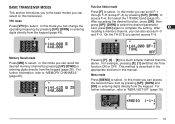
... entering digits directly from the keypad {page 45}. For further information, refer to select. Function Select mode Press [F] to "MEMORY CHANNELS" {page 26}. On the TH-D7E you cannot access F-6. 6 7 STA CON PACKET96BCONDUP 57 9 8 9 10 11 Pressing [F], [0] ~ [9] is described in the 13 appropriate sections in this transceiver. For example, pressing [F], [1] switches ... This method is a much simpler method than the above. BASIC TRANSCEIVER MODES This section introduces you to the basic modes you can select on this manual. 14 Menu mode 15 Press [MENU] to select.
... entering digits directly from the keypad {page 45}. For further information, refer to select. Function Select mode Press [F] to "MEMORY CHANNELS" {page 26}. On the TH-D7E you cannot access F-6. 6 7 STA CON PACKET96BCONDUP 57 9 8 9 10 11 Pressing [F], [0] ~ [9] is described in the 13 appropriate sections in this transceiver. For example, pressing [F], [1] switches ... This method is a much simpler method than the above. BASIC TRANSCEIVER MODES This section introduces you to the basic modes you can select on this manual. 14 Menu mode 15 Press [MENU] to select.
User Manual
Page 21
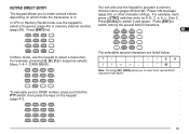
For example, pressing [1], [4], [1] in . You can also use the keypad to select a menu item. To manually send a DTMF number, press and hold the PTT switch, then press the keys on which mode the transceiver is in sequence selects Menu 1-4-1 (DATA BAND). ...
For example, pressing [1], [4], [1] in . You can also use the keypad to select a menu item. To manually send a DTMF number, press and hold the PTT switch, then press the keys on which mode the transceiver is in sequence selects Menu 1-4-1 (DATA BAND). ...

User Manual
Page 22
See the appropriate sections in this manual. 8 Press [OK] to complete the setting. 9 Press [MENU] to quickly select a menu item. to exit Menu mode. This method is described in the appropriate sections ... the appropriate level 2 No. MENU SET-UP 1 The Menu system on which menu item you can also enter level Nos. For example, pressing [1], [4], [1] in this manual. 16 blinks. 11 12 STA CON PACKET96BCONDUP 57 9 13 14 15 16 2 Press [UP]/ [DWN] to enter Menu mode. 10 • The current level 1 No...
See the appropriate sections in this manual. 8 Press [OK] to complete the setting. 9 Press [MENU] to quickly select a menu item. to exit Menu mode. This method is described in the appropriate sections ... the appropriate level 2 No. MENU SET-UP 1 The Menu system on which menu item you can also enter level Nos. For example, pressing [1], [4], [1] in this manual. 16 blinks. 11 12 STA CON PACKET96BCONDUP 57 9 13 14 15 16 2 Press [UP]/ [DWN] to enter Menu mode. 10 • The current level 1 No...
User Manual
Page 24
Manual/ PTT/ Auto See reference page. 10 ~ 2500 in steps of 10/ OFF Mile and °F/ Kilometer and °C Default OFF - Not used / NMEA See reference ... °F 65 Manual - See reference page. .5/ 1/ 2/ 3/ 5/ 10/ 20/ 30 minutes See reference page. 1 Level 1 2 3 4 5 1 RADIO 6 7 8 9 Level 1 10 11 12 13 14 15 16 17 2 APRS 18 19 20 21 22 23 18 Level 2 Level 3 5 AUX 6 TX Hold, 1750 Hz (TH-D7E) 7 Reset (TH-D7A) 7 VHF band narrow TX deviation (TH-D7E) 8 Advanced Intercept Point (TH-D7E) 9 Reset (TH-D7E) Level...
Manual/ PTT/ Auto See reference page. 10 ~ 2500 in steps of 10/ OFF Mile and °F/ Kilometer and °C Default OFF - Not used / NMEA See reference ... °F 65 Manual - See reference page. .5/ 1/ 2/ 3/ 5/ 10/ 20/ 30 minutes See reference page. 1 Level 1 2 3 4 5 1 RADIO 6 7 8 9 Level 1 10 11 12 13 14 15 16 17 2 APRS 18 19 20 21 22 23 18 Level 2 Level 3 5 AUX 6 TX Hold, 1750 Hz (TH-D7E) 7 Reset (TH-D7A) 7 VHF band narrow TX deviation (TH-D7E) 8 Advanced Intercept Point (TH-D7E) 9 Reset (TH-D7E) Level...
User Manual
Page 30
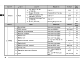
...) While using a repeater, ASC periodically monitors the strength of a signal that you receive directly from the other station. x Activating ASC while using a repeater, you can manually check the strength of a signal that contains Reverse ON status, ASC is switched OFF. Note: x Pressing the PTT switch causes the ASC indicator to be...
...) While using a repeater, ASC periodically monitors the strength of a signal that you receive directly from the other station. x Activating ASC while using a repeater, you can manually check the strength of a signal that contains Reverse ON status, ASC is switched OFF. Note: x Pressing the PTT switch causes the ASC indicator to be...

User Manual
Page 47
and Canada offer a service called Autopatch. MANUAL DIALING Manual Dialing requires only two steps to send DTMF tones. 1 Press and hold the PTT switch. 2 Press the keys in transmit mode for a quick call. So ...
and Canada offer a service called Autopatch. MANUAL DIALING Manual Dialing requires only two steps to send DTMF tones. 1 Press and hold the PTT switch. 2 Press the keys in transmit mode for a quick call. So ...
User Manual
Page 63
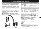
...antenna may cause malfunction. The cable that comes with the VC-H1 allows only image transfer from one station to this cable, contact your authorized KENWOOD dealer. The 13 SSTV mode currently set on the VC-H1. From this transceiver. Note: Use an optional PG-4V cable to connect the.... 2 3-1 MY CALL Call sign (8 digits max.) 3 4 3-2 MY CALL COL Color for call sign onto an image on the VC-H1, see the instruction manual for those information. to other stations. The 15 selectable SSTV modes are as follows: 16 • Robot (color) 36 • Robot (color) 72 17 •...
...antenna may cause malfunction. The cable that comes with the VC-H1 allows only image transfer from one station to this cable, contact your authorized KENWOOD dealer. The 13 SSTV mode currently set on the VC-H1. From this transceiver. Note: Use an optional PG-4V cable to connect the.... 2 3-1 MY CALL Call sign (8 digits max.) 3 4 3-2 MY CALL COL Color for call sign onto an image on the VC-H1, see the instruction manual for those information. to other stations. The 15 selectable SSTV modes are as follows: 16 • Robot (color) 36 • Robot (color) 72 17 •...
User Manual
Page 67
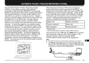
...Receive only 11 2 Can be scaled from the GPS receiver. You may be tracked must transmit beacons at certain intervals. It also allows you to manually enter position data (latitude/ longitude) 4 to track mobile stations on a map which require these equipment. 15 Note: x Turn OFF the transceiver ... GPS receiver. To have a GPS 5 receiver. Besides position data this function if you also need a GPS receiver. This 13 manual, however, does not describe APRS 14 communications which you of your current geographical position. The connection of another station.
...Receive only 11 2 Can be scaled from the GPS receiver. You may be tracked must transmit beacons at certain intervals. It also allows you to manually enter position data (latitude/ longitude) 4 to track mobile stations on a map which require these equipment. 15 Note: x Turn OFF the transceiver ... GPS receiver. To have a GPS 5 receiver. Besides position data this function if you also need a GPS receiver. This 13 manual, however, does not describe APRS 14 communications which you of your current geographical position. The connection of another station.

User Manual
Page 73
... allows users 7 to steps for specifying combinations of two 8 ASCII codes, for example, / and !. This 12 manual describes the APRS in the separate manual (document file) that comes with an optional PG-4W cable. SELECTING YOUR STATION ICON Select an icon which will be...1 Press [MENU] to enter Menu mode. 2 Press [2], [5] to exit Menu mode. One is a table identification code (either / 9 or \). KENWOOD SSTV Triangle Jogger Aircraft Jeep 1 Home Portable (tent) Yacht Boat Car Motorcycle Recreation 2 vehicle 3 Truck 4 5 Van 6 APRS supports approximately 200 icons.
... allows users 7 to steps for specifying combinations of two 8 ASCII codes, for example, / and !. This 12 manual describes the APRS in the separate manual (document file) that comes with an optional PG-4W cable. SELECTING YOUR STATION ICON Select an icon which will be...1 Press [MENU] to enter Menu mode. 2 Press [2], [5] to exit Menu mode. One is a table identification code (either / 9 or \). KENWOOD SSTV Triangle Jogger Aircraft Jeep 1 Home Portable (tent) Yacht Boat Car Motorcycle Recreation 2 vehicle 3 Truck 4 5 Van 6 APRS supports approximately 200 icons.

User Manual
Page 74
... 9 96 BCONDUP 13 Press [MENU] to MENU?" x Grid squares were developed to display the measured data, then press [OK]. x If using a GPS receiver, you to manually enter latitude and longitude data to transmit to other stations. 2 3 1 Press [MENU] to one hundredth digit). The world is expressed with 6 digits. Each field is...
... 9 96 BCONDUP 13 Press [MENU] to MENU?" x Grid squares were developed to display the measured data, then press [OK]. x If using a GPS receiver, you to manually enter latitude and longitude data to transmit to other stations. 2 3 1 Press [MENU] to one hundredth digit). The world is expressed with 6 digits. Each field is...
User Manual
Page 80
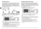
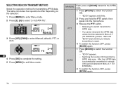
... selection: 3 1 Press [MENU] to enter Menu mode. 4 2 Press [2], [9] to select "2-9 (DATA TX)". 5 6 STA CON 96 BCONDUP 57 9 7 8 9 10 3 Press [UP]/ [DWN] to select Manual (default), PTT, or 11 Auto. 12 STA CON 96 BCONDUP 13 57 9 14 15 16 17 4 Press [OK] to complete the setting. 18 5 Press [MENU...] to exit Menu mode. 19 20 21 22 23 74 MANUAL PTT AUTO Each press of [BCON] transmits the APRS data. 1 Press [BCON] to indicate transmitting is automatically transmitted at intervals of the period selected in...
... selection: 3 1 Press [MENU] to enter Menu mode. 4 2 Press [2], [9] to select "2-9 (DATA TX)". 5 6 STA CON 96 BCONDUP 57 9 7 8 9 10 3 Press [UP]/ [DWN] to select Manual (default), PTT, or 11 Auto. 12 STA CON 96 BCONDUP 13 57 9 14 15 16 17 4 Press [OK] to complete the setting. 18 5 Press [MENU...] to exit Menu mode. 19 20 21 22 23 74 MANUAL PTT AUTO Each press of [BCON] transmits the APRS data. 1 Press [BCON] to indicate transmitting is automatically transmitted at intervals of the period selected in...

User Manual
Page 86
... 80 The table given on page 78 also shows indicators that have not yet been transmitted 5 times. A 13 reception acknowledgment is restored. You can also manually transmit all of those regardless of 1 minute. 3 For a message: 4 The transceiver repeats transmitting up to 5 times until a 5 reception acknowledgment is assigned to messages (or bulletins...
... 80 The table given on page 78 also shows indicators that have not yet been transmitted 5 times. A 13 reception acknowledgment is restored. You can also manually transmit all of those regardless of 1 minute. 3 For a message: 4 The transceiver repeats transmitting up to 5 times until a 5 reception acknowledgment is assigned to messages (or bulletins...
User Manual
Page 88
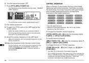
...will automatically enter transmit mode and send the corresponding command to the instruction manual for the mobile transceiver. Check the instruction manual for the 19 mobile transceiver. If not described, consult your authorized KENWOOD dealer, customer service, or 20 service center. 21 22 23 82... CONTROL OPERATION When in step 2. 13 • For the programming method, refer to the instruction manual for the mobile transceiver. 14 9 Select the ...
...will automatically enter transmit mode and send the corresponding command to the instruction manual for the mobile transceiver. Check the instruction manual for the 19 mobile transceiver. If not described, consult your authorized KENWOOD dealer, customer service, or 20 service center. 21 22 23 82... CONTROL OPERATION When in step 2. 13 • For the programming method, refer to the instruction manual for the mobile transceiver. 14 9 Select the ...