
User Manual
Page 2
... Amateur Radio products which conforms to purchase this KENWOOD FM Dual Bander. MODELS COVERED BY THIS MANUAL The models listed below are grateful you can program most of 200 memory channels to -read large LCD with a built-in Continuous Tone Coded Squelch System (CTCSS) rejects unwanted calls from other stations. • Equipped with only one band while receiving audio on both voice and data communications. TH...
... Amateur Radio products which conforms to purchase this KENWOOD FM Dual Bander. MODELS COVERED BY THIS MANUAL The models listed below are grateful you can program most of 200 memory channels to -read large LCD with a built-in Continuous Tone Coded Squelch System (CTCSS) rejects unwanted calls from other stations. • Equipped with only one band while receiving audio on both voice and data communications. TH...

User Manual
Page 3
... KENWOOD dealer, customer service, or service station. Contact your regular refuse or in municipal waste streams, which can generate radio frequency energy and, if not installed and used in some areas. KENWOOD's involvement in your area, call (toll free) 1-800-8-BATTERY (1-800-822-8837). The RBRC program is detected coming from the transceiver, turn OFF the power immediately and remove the battery case or the battery...
... KENWOOD dealer, customer service, or service station. Contact your regular refuse or in municipal waste streams, which can generate radio frequency energy and, if not installed and used in some areas. KENWOOD's involvement in your area, call (toll free) 1-800-8-BATTERY (1-800-822-8837). The RBRC program is detected coming from the transceiver, turn OFF the power immediately and remove the battery case or the battery...

User Manual
Page 4
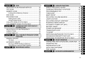
...TRANSFER 31 CHANNEL DISPLAY 31 PARTIAL OR FULL RESET 32 CONTENTS SUPPLIED ACCESSORIES 1 CONVENTIONS FOLLOWED IN THIS MANUAL ....... 1 CHAPTER 1 PREPARATION INSTALLING THE NiCd BATTERY PACK 2 CHARGING THE NiCd BATTERY PACK 2 INSTALLING THE ANTENNA 3 INSTALLING THE HAND STRAP/ BELT HOOK ......... 3 INSTALLING ALKALINE BATTERIES 4 CONNECTING WITH A REGULATED POWER SUPPLY 5 CONNECTING WITH A CIGARETTE LIGHTER SOCKET 5 CHAPTER 2 FIRST QSO CHAPTER 3 OPERATING BASICS CHAPTER 5 MENU SET-UP MENU ACCESS 16 MENU CONFIGURATION 17 CHAPTER 6 OPERATING THROUGH REPEATERS PROGRAMMING OFFSET 21...
...TRANSFER 31 CHANNEL DISPLAY 31 PARTIAL OR FULL RESET 32 CONTENTS SUPPLIED ACCESSORIES 1 CONVENTIONS FOLLOWED IN THIS MANUAL ....... 1 CHAPTER 1 PREPARATION INSTALLING THE NiCd BATTERY PACK 2 CHARGING THE NiCd BATTERY PACK 2 INSTALLING THE ANTENNA 3 INSTALLING THE HAND STRAP/ BELT HOOK ......... 3 INSTALLING ALKALINE BATTERIES 4 CONNECTING WITH A REGULATED POWER SUPPLY 5 CONNECTING WITH A CIGARETTE LIGHTER SOCKET 5 CHAPTER 2 FIRST QSO CHAPTER 3 OPERATING BASICS CHAPTER 5 MENU SET-UP MENU ACCESS 16 MENU CONFIGURATION 17 CHAPTER 6 OPERATING THROUGH REPEATERS PROGRAMMING OFFSET 21...
User Manual
Page 5
... Number 43 CHAPTER 11 MICROPHONE CONTROL CHAPTER 12 AUXILIARY FUNCTIONS 1 DIRECT FREQUENCY ENTRY 45 CHANGING FREQUENCY STEP SIZE 46 2 PROGRAMMABLE VFO 46 3 TONE ALERT 47 4 BEEP ON/OFF 47 5 ADJUSTING VOLUME BALANCE 48 6 LAMP FUNCTION 48 7 ADJUSTING DISPLAY CONTRAST 48 8 BLANKING A BAND DISPLAY 48 9 AUTOMATIC POWER OFF (APO 49 BATTERY SAVER 49 10 POWER-ON MESSAGE 50 11 TRANSCEIVER LOCK 50 12 TX INHIBIT 51 13 SWITCHING AM/FM MODE (TH...
... Number 43 CHAPTER 11 MICROPHONE CONTROL CHAPTER 12 AUXILIARY FUNCTIONS 1 DIRECT FREQUENCY ENTRY 45 CHANGING FREQUENCY STEP SIZE 46 2 PROGRAMMABLE VFO 46 3 TONE ALERT 47 4 BEEP ON/OFF 47 5 ADJUSTING VOLUME BALANCE 48 6 LAMP FUNCTION 48 7 ADJUSTING DISPLAY CONTRAST 48 8 BLANKING A BAND DISPLAY 48 9 AUTOMATIC POWER OFF (APO 49 BATTERY SAVER 49 10 POWER-ON MESSAGE 50 11 TRANSCEIVER LOCK 50 12 TX INHIBIT 51 13 SWITCHING AM/FM MODE (TH...

User Manual
Page 6
... CONTROL OPERATION 82 CHAPTER 19 SKY COMMAND 2 (TH-D7A ONLY) CONNECTING THE TRANSPORTER WITH THE HF TRANSCEIVER 84 PREPARATION FLOW 85 PROGRAMMING CALL SIGNS 86 PROGRAMMING A TONE FREQUENCY 86 CONTROL OPERATION 87 CHAPTER 20 MAINTENANCE GENERAL INFORMATION 89 SERVICE 89 SERVICE NOTE 89 CLEANING 89 TROUBLESHOOTING 90 CHAPTER 21 OPTIONAL ACCESSORIES CHAPTER 22 EQUIPMENT CONNECTIONS CONNECTING EQUIPMENT FOR REMOTE CONTROL 96 CONNECTING OTHER EXTERNAL EQUIPMENT 96 CHAPTER 23 SPECIFICATIONS APPENDIX QUICK REFERENCE GUIDE...
... CONTROL OPERATION 82 CHAPTER 19 SKY COMMAND 2 (TH-D7A ONLY) CONNECTING THE TRANSPORTER WITH THE HF TRANSCEIVER 84 PREPARATION FLOW 85 PROGRAMMING CALL SIGNS 86 PROGRAMMING A TONE FREQUENCY 86 CONTROL OPERATION 87 CHAPTER 20 MAINTENANCE GENERAL INFORMATION 89 SERVICE 89 SERVICE NOTE 89 CLEANING 89 TROUBLESHOOTING 90 CHAPTER 21 OPTIONAL ACCESSORIES CHAPTER 22 EQUIPMENT CONNECTIONS CONNECTING EQUIPMENT FOR REMOTE CONTROL 96 CONNECTING OTHER EXTERNAL EQUIPMENT 96 CHAPTER 23 SPECIFICATIONS APPENDIX QUICK REFERENCE GUIDE...
User Manual
Page 11
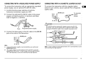
... transceiver and power supply are OFF. 2 Connect the optional PG-2W DC cable to the DC IN jack on the DC cable to the power supply; x The supply voltage must be between 5.5 V and 16 V to negative (-) terminal. Using the PG-2W DC cable in your authorized KENWOOD dealer. red lead to positive (+) terminal, and black lead to prevent damaging the transceiver. If input voltage exceeds...
... transceiver and power supply are OFF. 2 Connect the optional PG-2W DC cable to the DC IN jack on the DC cable to the power supply; x The supply voltage must be between 5.5 V and 16 V to negative (-) terminal. Using the PG-2W DC cable in your authorized KENWOOD dealer. red lead to positive (+) terminal, and black lead to prevent damaging the transceiver. If input voltage exceeds...

User Manual
Page 15
... transmitting. You can interfere with the supplied antenna near a poorly regulated power supply, that equipment. x The recommended duty cycle is not recommended 4 by KENWOOD, may cause the power supply to output an extremely high voltage. Time-Out Timer: Holding down the PTT switch for band 12 A and B. 13 Press [F], [MENU] to select high (default), low, or 14 economic low power (lowest). 15 • "H", "L", or "EL...
... transmitting. You can interfere with the supplied antenna near a poorly regulated power supply, that equipment. x The recommended duty cycle is not recommended 4 by KENWOOD, may cause the power supply to output an extremely high voltage. Time-Out Timer: Holding down the PTT switch for band 12 A and B. 13 Press [F], [MENU] to select high (default), low, or 14 economic low power (lowest). 15 • "H", "L", or "EL...

User Manual
Page 18
... transceiver mode. 12 Note: You can use the Tuning control instead of the functions with only one VHF frequency while receiving audio on another band by pressing [F], [A/B] in each operation step. " " indicates the current data band {page 55}. To transmit, you understand how to as 9 the Tuning control. These keys change frequencies, 10 memory channels, or other selections, depending on 2 bands (A and B). This manual often omits the Tuning control...
... transceiver mode. 12 Note: You can use the Tuning control instead of the functions with only one VHF frequency while receiving audio on another band by pressing [F], [A/B] in each operation step. " " indicates the current data band {page 55}. To transmit, you understand how to as 9 the Tuning control. These keys change frequencies, 10 memory channels, or other selections, depending on 2 bands (A and B). This manual often omits the Tuning control...
User Manual
Page 19
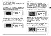
... "MENU SET-UP" {page 16}. 18 19 STA CON PACKET96BCONDUP 57 9 20 21 22 23 13 In this mode you can access 16 the desired menu item by pressing [UP]/ [DWN]; For further information, refer to select. VFO mode Press [VFO] to "MEMORY CHANNELS" {page 26}. In this mode you can change the operating frequency by pressing [UP]/ [DWN] or entering digits directly...
... "MENU SET-UP" {page 16}. 18 19 STA CON PACKET96BCONDUP 57 9 20 21 22 23 13 In this mode you can access 16 the desired menu item by pressing [UP]/ [DWN]; For further information, refer to select. VFO mode Press [VFO] to "MEMORY CHANNELS" {page 26}. In this mode you can change the operating frequency by pressing [UP]/ [DWN] or entering digits directly...

User Manual
Page 51
...; The display for Direct Frequency Entry appears. The previous data 20 remains unchanged for the 10 MHz 14 and 1 MHz digits and press [MHz]. AUXILIARY FUNCTIONS DIRECT FREQUENCY ENTRY If the desired operating frequency is far from the current band. x You cannot enter a frequency in use. If you press [VFO] while entering a frequency, the new 1 data is accepted for the digits entered and the previous 2 data remains...
...; The display for Direct Frequency Entry appears. The previous data 20 remains unchanged for the 10 MHz 14 and 1 MHz digits and press [MHz]. AUXILIARY FUNCTIONS DIRECT FREQUENCY ENTRY If the desired operating frequency is far from the current band. x You cannot enter a frequency in use. If you press [VFO] while entering a frequency, the new 1 data is accepted for the digits entered and the previous 2 data remains...
User Manual
Page 53
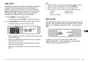
...; When a signal is received, an alarm sounds and the bell icon starts blinking. • Pressing the PTT switch while the bell icon is ON. Those settings are monitoring. You can also select "KEY" and 16 "KEY+NEW DATA". TONE ALERT Tone Alert provides an audible alarm when signals are received on the 8 keypad. The default is ON, you press a key on the frequency you can also switch this function...
...; When a signal is received, an alarm sounds and the bell icon starts blinking. • Pressing the PTT switch while the bell icon is ON. Those settings are monitoring. You can also select "KEY" and 16 "KEY+NEW DATA". TONE ALERT Tone Alert provides an audible alarm when signals are received on the 8 keypad. The default is ON, you press a key on the frequency you can also switch this function...
User Manual
Page 66
... the TH-D7, use it as the target station. Transmit a subaudible tone from the remote 3 control to the target 6 station. Then this transceiver causes the VC-H1 to capture an image, executes the 5 superimposition, and transmits the image to this transceiver connected with the VC-H1 for the 2 VC-H1. x "EXECUTING" appears and blinks on this transceiver, program a CTCSS frequency...
... the TH-D7, use it as the target station. Transmit a subaudible tone from the remote 3 control to the target 6 station. Then this transceiver causes the VC-H1 to capture an image, executes the 5 superimposition, and transmits the image to this transceiver connected with the VC-H1 for the 2 VC-H1. x "EXECUTING" appears and blinks on this transceiver, program a CTCSS frequency...
User Manual
Page 67
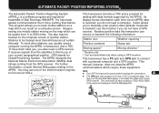
... making the connections. 16 x The GPS jack also accepts a 2.5 mm (1/10") 3-conductor plug. This program allows you to 2000 miles. It receives signals from the satellites to inform you to manually enter position data (latitude/ longitude) 4 to modify the cable end of each time correct APRS data 3 is the same as the plug on the map which can 6 receive or transmit the following information: 7 Station icon Weather reporting...
... making the connections. 16 x The GPS jack also accepts a 2.5 mm (1/10") 3-conductor plug. This program allows you to 2000 miles. It receives signals from the satellites to inform you to manually enter position data (latitude/ longitude) 4 to modify the cable end of each time correct APRS data 3 is the same as the plug on the map which can 6 receive or transmit the following information: 7 Station icon Weather reporting...
User Manual
Page 77
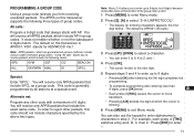
... [MENU] to enter Menu mode. 1 2 Press [2], [A] to enter alphanumeric characters in group codes. In order to receive packets which the cursor is APK001; For example, each press of 6 digits. The default on this transceiver supports the following codes. Using "All calls" allows you to reject other code with AP. Note: Menu 2-A allows you from receiving unwanted packets. the first 3 digit blinks. The default is generally programmed by...
... [MENU] to enter Menu mode. 1 2 Press [2], [A] to enter alphanumeric characters in group codes. In order to receive packets which the cursor is APK001; For example, each press of 6 digits. The default on this transceiver supports the following codes. Using "All calls" allows you to reject other code with AP. Note: Menu 2-A allows you from receiving unwanted packets. the first 3 digit blinks. The default is generally programmed by...

User Manual
Page 87
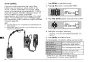
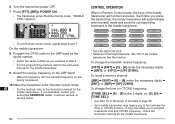
... 2 Press a numeric key 0 to 9 to enter a 3-digit secret 13 number. 14 • You can control one of the mobile transceiver 3 will find this handy transceiver. You will be controlled. 4 On the handy transceiver: 5 1 Press [PTT]+[VFO]+ POWER ON. 6 • The current secret access code number appears. Note: x You can remotely control only the mobile transceivers that have a KENWOOD multi-band mobile transceiver...
... 2 Press a numeric key 0 to 9 to enter a 3-digit secret 13 number. 14 • You can control one of the mobile transceiver 3 will find this handy transceiver. You will be controlled. 4 On the handy transceiver: 5 1 Press [PTT]+[VFO]+ POWER ON. 6 • The current secret access code number appears. Note: x You can remotely control only the mobile transceivers that have a KENWOOD multi-band mobile transceiver...
User Manual
Page 88
... method, refer to program a separate tone and CTCSS frequency. 6 Turn the transceiver power OFF. 7 Press [PTT]+[MR]+ POWER ON. 1 • The transceiver enters Remote Control mode. Each time you press the desired key, the handy transceiver will function as you to the instruction manual for the 19 mobile transceiver. To change the transmit/ receive frequency: ([VFO] ¬ [ENT] ¬ [0] ~ [9] (enter the necessary digits) ¬ [ENT]) or...
... method, refer to program a separate tone and CTCSS frequency. 6 Turn the transceiver power OFF. 7 Press [PTT]+[MR]+ POWER ON. 1 • The transceiver enters Remote Control mode. Each time you press the desired key, the handy transceiver will function as you to the instruction manual for the 19 mobile transceiver. To change the transmit/ receive frequency: ([VFO] ¬ [ENT] ¬ [0] ~ [9] (enter the necessary digits) ¬ [ENT]) or...
User Manual
Page 90
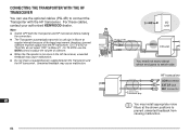
... (1/8") GPS I/O unit You need not worry about which end goes to which side 3.5 mm (1/8") 2-conductor plug HF transceiver COM connector EXT SP jack MIC connector You may cause malfunction. CONNECTING THE TRANSPORTER WITH THE HF TRANSCEIVER 1 2 You can use the MONI control to adjust the volume of sidetone. 9 x When the Transporter is too close to the HF transceiver, unwanted 10 feedback may install appropriate...
... (1/8") GPS I/O unit You need not worry about which end goes to which side 3.5 mm (1/8") 2-conductor plug HF transceiver COM connector EXT SP jack MIC connector You may cause malfunction. CONNECTING THE TRANSPORTER WITH THE HF TRANSCEIVER 1 2 You can use the MONI control to adjust the volume of sidetone. 9 x When the Transporter is too close to the HF transceiver, unwanted 10 feedback may install appropriate...
User Manual
Page 106
... LTEXT. The output data is 10 milliseconds. Enter a space between the TNC and the GPS receiver. The unit of all the commands. Selects 4800 or 9600 bps as the transfer rate between the command name and a class identifier; DISPLAY H. When ON, starting key entry causes the computer to the computer. this data is 1 second. ex. A (ASYNC): RS-232C port parameters...
... LTEXT. The output data is 10 milliseconds. Enter a space between the TNC and the GPS receiver. The unit of all the commands. Selects 4800 or 9600 bps as the transfer rate between the command name and a class identifier; DISPLAY H. When ON, starting key entry causes the computer to the computer. this data is 1 second. ex. A (ASYNC): RS-232C port parameters...
User Manual
Page 110
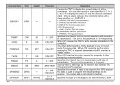
... Memory Channel Lockout ON/ OFF Tone ON/ OFF Tone Frequency Select Tone Freq. Page 66 62 68 69 67 70 75 72 74 71 75 65 104 Key Operation Selection [2], [1] ¬ [UP]/ [DWN] ¬ [OK] ¬ Enter up to 9 digits My Call Sign [2], [2] ¬ [UP]/ [DWN] ¬ [OK] GPS Receiver [2], [3] ¬ Latitude/ See reference page Longitude Data [2], [4] ¬...
... Memory Channel Lockout ON/ OFF Tone ON/ OFF Tone Frequency Select Tone Freq. Page 66 62 68 69 67 70 75 72 74 71 75 65 104 Key Operation Selection [2], [1] ¬ [UP]/ [DWN] ¬ [OK] ¬ Enter up to 9 digits My Call Sign [2], [2] ¬ [UP]/ [DWN] ¬ [OK] GPS Receiver [2], [3] ¬ Latitude/ See reference page Longitude Data [2], [4] ¬...
User Manual
Page 111
... only) ...... 83 Slow-Scan Television (SSTV 57 Specifications 97 Squelch, Adjusting 8 TNC 53 Tone Activating 22 Freq. ID 25 Frequency, Selecting 22 Tone Alert 47 Transmit Power, Selecting 9 Troubleshooting 90 TX Deviation (TH-D7E only 51 TX Inhibit 51 Volume Balance, Adjusting 48 Wireless Remote Control (TH-D7A only 81 53 Accessories Optional 94 Supplied 1 Advanced Intercept Point (AIP) ......... 51 APRS Programming 66~75 Receiving 63 Transmitting 74 APRS...
... only) ...... 83 Slow-Scan Television (SSTV 57 Specifications 97 Squelch, Adjusting 8 TNC 53 Tone Activating 22 Freq. ID 25 Frequency, Selecting 22 Tone Alert 47 Transmit Power, Selecting 9 Troubleshooting 90 TX Deviation (TH-D7E only 51 TX Inhibit 51 Volume Balance, Adjusting 48 Wireless Remote Control (TH-D7A only 81 53 Accessories Optional 94 Supplied 1 Advanced Intercept Point (AIP) ......... 51 APRS Programming 66~75 Receiving 63 Transmitting 74 APRS...


