

User Manual
Page 3
...and recycle Ni-Cd batteries after their operating life has expired. For information on KENWOOD nickel-cadmium (Ni-Cd) battery packs indicates KENWOOD's voluntary participation in this program is made. KENWOOD's involvement in an industry program to disposing Ni-Cd batteries with high output power ... may cause harmful interference to prevent fire, personal injury, or transceiver damage: • Do not transmit with your authorized KENWOOD dealer, customer service, or service station. Contact your regular refuse or in municipal waste streams, which the receiver is detected...
...and recycle Ni-Cd batteries after their operating life has expired. For information on KENWOOD nickel-cadmium (Ni-Cd) battery packs indicates KENWOOD's voluntary participation in this program is made. KENWOOD's involvement in an industry program to disposing Ni-Cd batteries with high output power ... may cause harmful interference to prevent fire, personal injury, or transceiver damage: • Do not transmit with your authorized KENWOOD dealer, customer service, or service station. Contact your regular refuse or in municipal waste streams, which the receiver is detected...

User Manual
Page 4
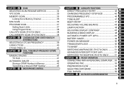
...FREQUENCIES 27 RECALLING A MEMORY CHANNEL 28 CLEARING A MEMORY CHANNEL 28 NAMING A MEMORY CHANNEL 29 CALL CHANNEL (TH-D7A ONLY 30 Recalling the Call Channel 30 Reprogramming the Call Channel 30 MEMORY-TO-VFO TRANSFER 31 CHANNEL DISPLAY... ACCESSORIES 1 CONVENTIONS FOLLOWED IN THIS MANUAL ....... 1 CHAPTER 1 PREPARATION INSTALLING THE NiCd BATTERY PACK 2 CHARGING THE NiCd BATTERY PACK 2 INSTALLING THE ANTENNA 3 INSTALLING THE HAND STRAP/ BELT HOOK ......... 3 INSTALLING ALKALINE BATTERIES 4 CONNECTING WITH A REGULATED POWER SUPPLY 5 CONNECTING WITH A CIGARETTE LIGHTER SOCKET 5 ...
...FREQUENCIES 27 RECALLING A MEMORY CHANNEL 28 CLEARING A MEMORY CHANNEL 28 NAMING A MEMORY CHANNEL 29 CALL CHANNEL (TH-D7A ONLY 30 Recalling the Call Channel 30 Reprogramming the Call Channel 30 MEMORY-TO-VFO TRANSFER 31 CHANNEL DISPLAY... ACCESSORIES 1 CONVENTIONS FOLLOWED IN THIS MANUAL ....... 1 CHAPTER 1 PREPARATION INSTALLING THE NiCd BATTERY PACK 2 CHARGING THE NiCd BATTERY PACK 2 INSTALLING THE ANTENNA 3 INSTALLING THE HAND STRAP/ BELT HOOK ......... 3 INSTALLING ALKALINE BATTERIES 4 CONNECTING WITH A REGULATED POWER SUPPLY 5 CONNECTING WITH A CIGARETTE LIGHTER SOCKET 5 ...
User Manual
Page 5
... Locking Out a Memory Channel 36 MHz SCAN 36 PROGRAM SCAN 37 Setting Scan Limits 37 Using Program Scan 38 CALL/VFO SCAN (TH-D7A ONLY 38 CALL/MEMORY SCAN (TH-D7A ONLY 38 CHAPTER 9 CONTINUOUS TONE CODED SQUELCH SYSTEM (CTCSS) SELECTING A CTCSS FREQUENCY 39 USING CTCSS 40 CTCSS FREQ. ID... BAND DISPLAY 48 9 AUTOMATIC POWER OFF (APO 49 BATTERY SAVER 49 10 POWER-ON MESSAGE 50 11 TRANSCEIVER LOCK 50 12 TX INHIBIT 51 13 SWITCHING AM/FM MODE (TH-D7A ONLY 51 14 ADVANCED INTERCEPT POINT (AIP 51 15 SWITCHING TX DEVIATION (TH-D7E ONLY) ......... 51 16 CHAPTER 13 PACKET OPERATION 17 ...
... Locking Out a Memory Channel 36 MHz SCAN 36 PROGRAM SCAN 37 Setting Scan Limits 37 Using Program Scan 38 CALL/VFO SCAN (TH-D7A ONLY 38 CALL/MEMORY SCAN (TH-D7A ONLY 38 CHAPTER 9 CONTINUOUS TONE CODED SQUELCH SYSTEM (CTCSS) SELECTING A CTCSS FREQUENCY 39 USING CTCSS 40 CTCSS FREQ. ID... BAND DISPLAY 48 9 AUTOMATIC POWER OFF (APO 49 BATTERY SAVER 49 10 POWER-ON MESSAGE 50 11 TRANSCEIVER LOCK 50 12 TX INHIBIT 51 13 SWITCHING AM/FM MODE (TH-D7A ONLY 51 14 ADVANCED INTERCEPT POINT (AIP 51 15 SWITCHING TX DEVIATION (TH-D7E ONLY) ......... 51 16 CHAPTER 13 PACKET OPERATION 17 ...
User Manual
Page 7
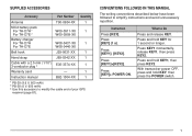
Press and hold KEY, then press the POWER switch. 1 SUPPLIED ACCESSORIES Accessory Part Number Quantity Antenna NiCd battery pack For TH-D7A 1 For TH-D7E 2 Battery charger For TH-D7A For TH-D7E Belt hook T90-0634-XX 1 W09-0911-XX 1 W09-0909-XX W08-0437-XX 1 W08-0440-XX J29-0631-XX 1 Hand strap J69-0342-XX 1 ...
Press and hold KEY, then press the POWER switch. 1 SUPPLIED ACCESSORIES Accessory Part Number Quantity Antenna NiCd battery pack For TH-D7A 1 For TH-D7E 2 Battery charger For TH-D7A For TH-D7E Belt hook T90-0634-XX 1 W09-0911-XX 1 W09-0909-XX W08-0437-XX 1 W08-0440-XX J29-0631-XX 1 Hand strap J69-0342-XX 1 ...
User Manual
Page 8
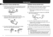
.... 1 Confirm that the transceiver power is designed to charge only the provided PB-38 or PB-39 NiCd battery pack. x Exceeding the specified charge period shortens the useful life of battery packs will take approximately 16 hours for PB-38 or 15 hours for PB-39. 4 After 16 hours ... charger into an AC wall outlet. • Charging starts and will damage the charger and battery pack. 2 Charging other models of the NiCd battery pack. x The provided charger is OFF. • While charging the battery pack, leave the transceiver power OFF. 2 Insert the DC plug from the AC wall outlet...
.... 1 Confirm that the transceiver power is designed to charge only the provided PB-38 or PB-39 NiCd battery pack. x Exceeding the specified charge period shortens the useful life of battery packs will take approximately 16 hours for PB-38 or 15 hours for PB-39. 4 After 16 hours ... charger into an AC wall outlet. • Charging starts and will damage the charger and battery pack. 2 Charging other models of the NiCd battery pack. x The provided charger is OFF. • While charging the battery pack, leave the transceiver power OFF. 2 Insert the DC plug from the AC wall outlet...
User Manual
Page 9
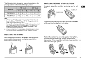
...its base, and screw the antenna into the connector on the 16 transceiver. x If the operating time of a fully charged NiCd battery pack is much shorter than before, the battery life is over the right groove. 17 18 19 PC GPS PC GPS PC GPS 20 21 22 23 3 Then install the... belt hook. The following table shows the approximate battery life (hours) relative to full capacity. To resolve this range may not fully charge the pack. Last, position the cable over . Charging outside this ...
...its base, and screw the antenna into the connector on the 16 transceiver. x If the operating time of a fully charged NiCd battery pack is much shorter than before, the battery life is over the right groove. 17 18 19 PC GPS PC GPS PC GPS 20 21 22 23 3 Then install the... belt hook. The following table shows the approximate battery life (hours) relative to full capacity. To resolve this range may not fully charge the pack. Last, position the cable over . Charging outside this ...
User Manual
Page 10
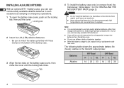
... use high quality alkaline batteries rather than manganese batteries to enjoy longer periods of battery life. x When the battery voltage is recommended to use commercially available NiCd batteries. Note: x It is low, replace all four old batteries with those marked on the bottom of batteries together. x If you can use commercially available alkaline batteries in fire because extremely...
... use high quality alkaline batteries rather than manganese batteries to enjoy longer periods of battery life. x When the battery voltage is recommended to use commercially available NiCd batteries. Note: x It is low, replace all four old batteries with those marked on the bottom of batteries together. x If you can use commercially available alkaline batteries in fire because extremely...

User Manual
Page 15
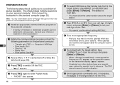
... transceiver to output an extremely high voltage. x The recommended duty cycle is still reliable. Release, then press the PTT switch to 11 reduce battery consumption, if communication is 1 minute of transmission and 1 3 minutes of reception. Extended transmissions in a normal tone of voice. •...or B lights red depending on which band you finish speaking, release the PTT switch. You can interfere with that is not recommended 4 by KENWOOD, may cause the back of the transceiver to get hot. 2 x Transmitting with the supplied antenna near a poorly regulated power supply, that...
... transceiver to output an extremely high voltage. x The recommended duty cycle is still reliable. Release, then press the PTT switch to 11 reduce battery consumption, if communication is 1 minute of transmission and 1 3 minutes of reception. Extended transmissions in a normal tone of voice. •...or B lights red depending on which band you finish speaking, release the PTT switch. You can interfere with that is not recommended 4 by KENWOOD, may cause the back of the transceiver to get hot. 2 x Transmitting with the supplied antenna near a poorly regulated power supply, that...
User Manual
Page 17
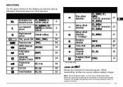
While transmitting, shows the current relative battery charge. 21 Note: Electromagnetic fields, such as those produced by static 22 electricity, may occasionally cause the display to function abnormally. 23 However, the display will see various indicators that show what you will typically return to normal operation within a couple of received signals. INDICATORS On the upper section of the display you have selected. 1 2 3 4 5 6 7 8 9 10 11 12 13 14 15 16 17 1 TH-D7E only 18 19 57 9 20 Shows the strength of minutes. 11
While transmitting, shows the current relative battery charge. 21 Note: Electromagnetic fields, such as those produced by static 22 electricity, may occasionally cause the display to function abnormally. 23 However, the display will see various indicators that show what you will typically return to normal operation within a couple of received signals. INDICATORS On the upper section of the display you have selected. 1 2 3 4 5 6 7 8 9 10 11 12 13 14 15 16 17 1 TH-D7E only 18 19 57 9 20 Shows the strength of minutes. 11
User Manual
Page 23
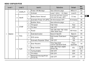
... 1 DISPLAY 2 SAVE 3 DTMF 1 RADIO 4 TNC 5 AUX Level 3 Selections 1 Power-ON Message See reference page. 2 Contrast Level 1 (min.) ~ 16 (max.) 1 Battery Saver Interval 0.2/ 0.4/ 0.6/ 0.8/ 1.0/ 2.0/ 3.0/ 4.0/ 5.0 sec./ OFF 2 Automatic Power Off (APO) 30/ 60 minutes/ OFF 1 Number Store See reference page. 2 TX speed...Carrier-Operated/ Seek 3 Beep function OFF/ KEY/ KEY+NEW DATA/ ALL 4 Tuning Enable ON/ OFF 5 TX Inhibit ON/ OFF 6 Advanced Intercept Point (TH-D7A) ON/ OFF Default Ref. 1 page 2 HELLO !! 50 3 Level 8 48 4 1.0 sec. 49 5 6 30 minutes 49 7 - 42 ...
... 1 DISPLAY 2 SAVE 3 DTMF 1 RADIO 4 TNC 5 AUX Level 3 Selections 1 Power-ON Message See reference page. 2 Contrast Level 1 (min.) ~ 16 (max.) 1 Battery Saver Interval 0.2/ 0.4/ 0.6/ 0.8/ 1.0/ 2.0/ 3.0/ 4.0/ 5.0 sec./ OFF 2 Automatic Power Off (APO) 30/ 60 minutes/ OFF 1 Number Store See reference page. 2 TX speed...Carrier-Operated/ Seek 3 Beep function OFF/ KEY/ KEY+NEW DATA/ ALL 4 Tuning Enable ON/ OFF 5 TX Inhibit ON/ OFF 6 Advanced Intercept Point (TH-D7A) ON/ OFF Default Ref. 1 page 2 HELLO !! 50 3 Level 8 48 4 1.0 sec. 49 5 6 30 minutes 49 7 - 42 ...
User Manual
Page 55
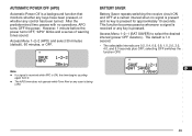
... the power. The default is ON, the timer begins counting again from 0. Access Menu 1-2-2 (APO) and select 30 minutes (default), 60 minutes, or OFF. BATTERY SAVER Battery Saver repeats switching the receive circuit ON 1 and OFF at a certain interval when no signal is pressed. 4 Access Menu 1-2-1 (BAT SAVER) to select the desired...
... the power. The default is ON, the timer begins counting again from 0. Access Menu 1-2-2 (APO) and select 30 minutes (default), 60 minutes, or OFF. BATTERY SAVER Battery Saver repeats switching the receive circuit ON 1 and OFF at a certain interval when no signal is pressed. 4 Access Menu 1-2-1 (BAT SAVER) to select the desired...
User Manual
Page 60
... transmit in advance. First connect the 3 transceiver to the personal computer {page 53}. 4 Note: You may want to monitor packets which informs you may switch Battery Saver OFF {page 49} to prevent the initial 5 portion of freeware or shareware programs can be obtained in various ways. u Type MYCALL (or MY) then...
... transmit in advance. First connect the 3 transceiver to the personal computer {page 53}. 4 Note: You may want to monitor packets which informs you may switch Battery Saver OFF {page 49} to prevent the initial 5 portion of freeware or shareware programs can be obtained in various ways. u Type MYCALL (or MY) then...

User Manual
Page 96
... [A/B]+ POWER ON to switch OFF 50 12 Tuning control do not function. Page 4 Nothing appears on the 1 Low supply voltage 1 Recharge the battery pack or replace 2, 4 5 display when the the batteries. 6 transceiver is switched ON, or the display is 1 Press [F] (1 s) to exit 31 13 Display mode. Replace the fuse. 11 Most keys...
... [A/B]+ POWER ON to switch OFF 50 12 Tuning control do not function. Page 4 Nothing appears on the 1 Low supply voltage 1 Recharge the battery pack or replace 2, 4 5 display when the the batteries. 6 transceiver is switched ON, or the display is 1 Press [F] (1 s) to exit 31 13 Display mode. Replace the fuse. 11 Most keys...

User Manual
Page 100
OPTIONAL ACCESSORIES 1 2 SMC-32 Speaker 3 Microphone 4 SMC-33 Remote Control Speaker Microphone SMC-34 Remote Control Speaker Microphone (with Volume Control) HMC-3 Head Set with VOX/PTT 5 6 7 8 9 EMC-3 10 Clip Microphone 11 with Earphone PB-38 Standard Battery Pack (6 V/ 650 mAh) PB-39 High-power Battery Pack (9.6 V/ 600 mAh) BT-11 Battery Case 12 13 14 15 16 17 BC-17 18 Wall Charger BC-19 Rapid Charger SC-40 Soft Case PG-2W DC Cable 19 20 21 22 23 94
OPTIONAL ACCESSORIES 1 2 SMC-32 Speaker 3 Microphone 4 SMC-33 Remote Control Speaker Microphone SMC-34 Remote Control Speaker Microphone (with Volume Control) HMC-3 Head Set with VOX/PTT 5 6 7 8 9 EMC-3 10 Clip Microphone 11 with Earphone PB-38 Standard Battery Pack (6 V/ 650 mAh) PB-39 High-power Battery Pack (9.6 V/ 600 mAh) BT-11 Battery Case 12 13 14 15 16 17 BC-17 18 Wall Charger BC-19 Rapid Charger SC-40 Soft Case PG-2W DC Cable 19 20 21 22 23 94
User Manual
Page 103
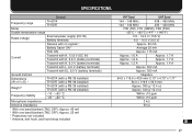
... 2 TNC ON Current Transmit with H, 13.8 V (DC IN) Transmit with H, 9.6 V (battery terminals) Transmit with H, 6.0 V (battery terminals) Transmit with L, 6.0 V (battery terminals) Transmit with EL, 6.0 V (battery terminals) Ground method Dimensions (W x H x D) 3 TH-D7A (with a PB-39 installed) TH-D7E (with a PB-38 installed) Weight 4 TH-D7A (with a PB-39 installed) TH-D7E (with a PB-38 installed) Frequency stability -10 ~ +50 °C -20 ~ +60...
... 2 TNC ON Current Transmit with H, 13.8 V (DC IN) Transmit with H, 9.6 V (battery terminals) Transmit with H, 6.0 V (battery terminals) Transmit with L, 6.0 V (battery terminals) Transmit with EL, 6.0 V (battery terminals) Ground method Dimensions (W x H x D) 3 TH-D7A (with a PB-39 installed) TH-D7E (with a PB-38 installed) Weight 4 TH-D7A (with a PB-39 installed) TH-D7E (with a PB-38 installed) Frequency stability -10 ~ +50 °C -20 ~ +60...

User Manual
Page 104
... MHz 450 kHz 455 kHz 0.18 µV or less 0.1 µV or less 13 Selectivity (-6 dB) 14 Selectivity (-40 dB) Audio output 15 (10% distortion) 9.6 V (battery terminals) 6.0 V (battery terminals) 16 1 VHF sub-band: 0.28 µV or less 12 kHz or more 28 kHz or less 450 mW or higher (8 Ω load) 300 mW...
... MHz 450 kHz 455 kHz 0.18 µV or less 0.1 µV or less 13 Selectivity (-6 dB) 14 Selectivity (-40 dB) Audio output 15 (10% distortion) 9.6 V (battery terminals) 6.0 V (battery terminals) 16 1 VHF sub-band: 0.28 µV or less 12 kHz or more 28 kHz or less 450 mW or higher (8 Ω load) 300 mW...
User Manual
Page 109
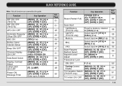
...DWN] ¬ [OK] 8 ON/ OFF F (1 s) 50 Tuning Control Enable [MENU], [1], [5], [4] ¬ [UP]/ [DWN] ¬ [OK] 50 TX Deviation Switch [MENU], [1], [5], [7] ¬ (TH-D7E only) [UP]/ [DWN] ¬ [OK] 51 TX Inhibit ON/ OFF [MENU], [1], [5], [5] ¬ [UP]/ [DWN] ¬ [OK] 51 103 QUICK REFERENCE GUIDE Note: Not all functions... are covered by this guide. Function Key Operation AIP ON/ OFF (TH-D7A) AIP ON/ OFF (TH-D7E) APO ON/ OFF Automatic Repeater Offset ON/ OFF ASC ON Battery Saver Interval Select Beep ON/ OFF Channel Display ON/ OFF Data Band Select Display...
...DWN] ¬ [OK] 8 ON/ OFF F (1 s) 50 Tuning Control Enable [MENU], [1], [5], [4] ¬ [UP]/ [DWN] ¬ [OK] 50 TX Deviation Switch [MENU], [1], [5], [7] ¬ (TH-D7E only) [UP]/ [DWN] ¬ [OK] 51 TX Inhibit ON/ OFF [MENU], [1], [5], [5] ¬ [UP]/ [DWN] ¬ [OK] 51 103 QUICK REFERENCE GUIDE Note: Not all functions... are covered by this guide. Function Key Operation AIP ON/ OFF (TH-D7A) AIP ON/ OFF (TH-D7E) APO ON/ OFF Automatic Repeater Offset ON/ OFF ASC ON Battery Saver Interval Select Beep ON/ OFF Channel Display ON/ OFF Data Band Select Display...
User Manual
Page 111
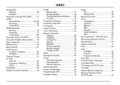
ID 25 Frequency, Selecting 22 Tone Alert 47 Transmit Power, Selecting 9 Troubleshooting 90 TX Deviation (TH-D7E only 51 TX Inhibit 51 Volume Balance, Adjusting 48 Wireless Remote Control (TH-D7A only 81 53 ID 40 Frequency, Selecting 39 Using 40 Data Band 55 Display Contrast, Adjusting 48 INDEX DTMF Making ... 74 APRS Message Entering 79 Receiving 77 Transmitting 80 Automatic Power Off (APO 49 Automatic Simplex Check (ASC) ...... 24 Band, Selecting 7, 12 Battery Saver 49 Beep ON/OFF 47 Call Channel Contents, Changing 30 Recalling 30 Channel Display 31 CTCSS Freq.
ID 25 Frequency, Selecting 22 Tone Alert 47 Transmit Power, Selecting 9 Troubleshooting 90 TX Deviation (TH-D7E only 51 TX Inhibit 51 Volume Balance, Adjusting 48 Wireless Remote Control (TH-D7A only 81 53 ID 40 Frequency, Selecting 39 Using 40 Data Band 55 Display Contrast, Adjusting 48 INDEX DTMF Making ... 74 APRS Message Entering 79 Receiving 77 Transmitting 80 Automatic Power Off (APO 49 Automatic Simplex Check (ASC) ...... 24 Band, Selecting 7, 12 Battery Saver 49 Beep ON/OFF 47 Call Channel Contents, Changing 30 Recalling 30 Channel Display 31 CTCSS Freq.
