

User Manual
Page 1
INSTRUCTION MANUAL POWER GRP TX BUSY VOL CH POWER GRP TX BUSY VOL CALL MON SCAN SP OPT A B C OST MON SCN CH VHF FM TRANSCEIVER TK-690 series VHF FM TRANSCEIVER TK-790 series UHF FM TRANSCEIVER TK-890 series © B62-0970-20 (K) 09 08 07 06 05 04 03 02
INSTRUCTION MANUAL POWER GRP TX BUSY VOL CH POWER GRP TX BUSY VOL CALL MON SCAN SP OPT A B C OST MON SCN CH VHF FM TRANSCEIVER TK-690 series VHF FM TRANSCEIVER TK-790 series UHF FM TRANSCEIVER TK-890 series © B62-0970-20 (K) 09 08 07 06 05 04 03 02
User Manual
Page 2
We are grateful you will provide dependable communications to keep personnel operating at peak efficiency. KENWOOD transceivers incorporate the latest in advanced technology. As a result, we feel strongly that you chose KENWOOD for your land mobile applications. MODELS COVERED BY THIS MANUAL • TK-690H: VHF FM Transceiver • TK-790: VHF FM Transceiver • TK-790H: VHF FM Transceiver • TK-890: UHF FM Transceiver • TK-890H: UHF FM Transceiver We believe this easy-to-use transceiver will be pleased with the quality and features of this product. THANK YOU!
We are grateful you will provide dependable communications to keep personnel operating at peak efficiency. KENWOOD transceivers incorporate the latest in advanced technology. As a result, we feel strongly that you chose KENWOOD for your land mobile applications. MODELS COVERED BY THIS MANUAL • TK-690H: VHF FM Transceiver • TK-790: VHF FM Transceiver • TK-790H: VHF FM Transceiver • TK-890: UHF FM Transceiver • TK-890H: UHF FM Transceiver We believe this easy-to-use transceiver will be pleased with the quality and features of this product. THANK YOU!
User Manual
Page 3
.... The user could lose the authority to operate this equipment may be determined by one or more of the following statements may cause harmful interference unless the modifications are expressly approved in a gasoline service station. However, there is encouraged to try to Part 15 of radio frequency burns or related physical injury. ◆ DYNAMITE BLASTING CAPS Turn OFF...
.... The user could lose the authority to operate this equipment may be determined by one or more of the following statements may cause harmful interference unless the modifications are expressly approved in a gasoline service station. However, there is encouraged to try to Part 15 of radio frequency burns or related physical injury. ◆ DYNAMITE BLASTING CAPS Turn OFF...
User Manual
Page 4
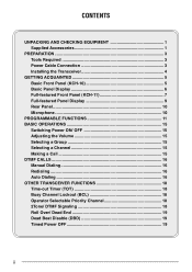
... EQUIPMENT 1 Supplied Accessories 1 PREPARATION 3 Tools Required 3 Power Cable Connection 3 Installing the Transceiver 4 GETTING ACQUAINTED 5 Basic Front Panel (KCH-10 5 Basic Panel Display 6 Full-featured Front Panel (KCH-11 7 Full-featured Panel Display 9 Rear Panel 10 Microphone 10 PROGRAMMABLE FUNCTIONS 11 BASIC OPERATIONS 15 Switching Power ON/ OFF 15 Adjusting the Volume 15 Selecting a Group 15 Selecting a Channel 15 Making a Call 15 DTMF CALLS 16 Manual Dialing...
... EQUIPMENT 1 Supplied Accessories 1 PREPARATION 3 Tools Required 3 Power Cable Connection 3 Installing the Transceiver 4 GETTING ACQUAINTED 5 Basic Front Panel (KCH-10 5 Basic Panel Display 6 Full-featured Front Panel (KCH-11 7 Full-featured Panel Display 9 Rear Panel 10 Microphone 10 PROGRAMMABLE FUNCTIONS 11 BASIC OPERATIONS 15 Switching Power ON/ OFF 15 Adjusting the Volume 15 Selecting a Group 15 Selecting a Channel 15 Making a Call 15 DTMF CALLS 16 Manual Dialing...
User Manual
Page 5
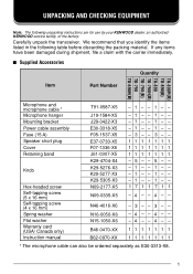
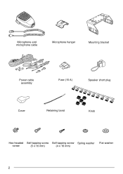
... you identify the items listed in the following unpacking instructions are for use by your KENWOOD dealer, an authorized KENWOOD service facility, or the factory. If any items have been damaged during shipment, file a claim with the carrier immediately. ■ Supplied Accessories Quantity Item Part Number TK-890 (B) TK-890(B) TK-890 TK-790 (B) TK-790 (B) TK-790 TK-690 (B) H H H Microphone and microphone cable 1 Microphone hanger Mounting bracket Power cable assembly Fuse (15 A) Speaker short plug Cover Retaining band Knob Hex-headed...
... you identify the items listed in the following unpacking instructions are for use by your KENWOOD dealer, an authorized KENWOOD service facility, or the factory. If any items have been damaged during shipment, file a claim with the carrier immediately. ■ Supplied Accessories Quantity Item Part Number TK-890 (B) TK-890(B) TK-890 TK-790 (B) TK-790 (B) TK-790 TK-690 (B) H H H Microphone and microphone cable 1 Microphone hanger Mounting bracket Power cable assembly Fuse (15 A) Speaker short plug Cover Retaining band Knob Hex-headed...
User Manual
Page 6
Microphone and microphone cable Microphone hanger Mounting bracket Power cable assembly Fuse (15 A) Speaker short plug Cover Retaining band Knob Hex-headed Self-tapping screw Self-tapping screw Spring washer Flat washer screw (5 x 16 mm) (4 x 16 mm) 2
Microphone and microphone cable Microphone hanger Mounting bracket Power cable assembly Fuse (15 A) Speaker short plug Cover Retaining band Knob Hex-headed Self-tapping screw Self-tapping screw Spring washer Flat washer screw (5 x 16 mm) (4 x 16 mm) 2
User Manual
Page 7
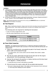
..., use by your KENWOOD dealer, an authorized KENWOOD service facility, or the factory. ■ Tools Required Note: Before installing the transceiver, always check how far the mounting screws will extend below ) and circle cutters Drill Bit Size 4.2 mm (5/32 inch) 3.2 mm (1/8 inch) Purpose 5 x 16 mm self-tapping screws 4 x 16 mm self-tapping screws ■ Power Cable Connection CAUTION: THE TRANSCEIVER OPERATES IN...
..., use by your KENWOOD dealer, an authorized KENWOOD service facility, or the factory. ■ Tools Required Note: Before installing the transceiver, always check how far the mounting screws will extend below ) and circle cutters Drill Bit Size 4.2 mm (5/32 inch) 3.2 mm (1/8 inch) Purpose 5 x 16 mm self-tapping screws 4 x 16 mm self-tapping screws ■ Power Cable Connection CAUTION: THE TRANSCEIVER OPERATES IN...
User Manual
Page 8
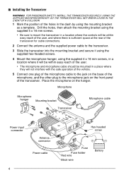
... it will not interfere with the safe operation of the vehicle. 5 Connect one plug of the microphone cable to the jack on the base of the microphone, and the other plug to the microphone jack on the hanger. Microphone Microphone hanger Mounting bracket Transceiver Microphone cable Power input connector Antenna connector Power cable 4 Hex headed screw Fuse Fuse holder Red wire Black wire Battery Drill the holes, then attach the mounting bracket using the supplied 5 x 16 mm screws. • Be sure to...
... it will not interfere with the safe operation of the vehicle. 5 Connect one plug of the microphone cable to the jack on the base of the microphone, and the other plug to the microphone jack on the hanger. Microphone Microphone hanger Mounting bracket Transceiver Microphone cable Power input connector Antenna connector Power cable 4 Hex headed screw Fuse Fuse holder Red wire Black wire Battery Drill the holes, then attach the mounting bracket using the supplied 5 x 16 mm screws. • Be sure to...
User Manual
Page 9
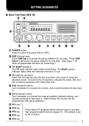
... key 5 y CH (Channel) control Turn clockwise to increase the channel selection (default setting), and counterclockwise to decrease it . (Alternatively, this connector and secure it becomes free. GETTING ACQUAINTED ■ Basic Front Panel (KCH-10) qw POWER GRP e TX BUSY VOL CH r t y u i o !0 !1 q POWER switch Press to increase the group selection by one step. t VOL (Volume) control Turn clockwise to increase the volume, and counterclockwise to decrease it . r Microphone connector...
... key 5 y CH (Channel) control Turn clockwise to increase the channel selection (default setting), and counterclockwise to decrease it . (Alternatively, this connector and secure it becomes free. GETTING ACQUAINTED ■ Basic Front Panel (KCH-10) qw POWER GRP e TX BUSY VOL CH r t y u i o !0 !1 q POWER switch Press to increase the group selection by one step. t VOL (Volume) control Turn clockwise to increase the volume, and counterclockwise to decrease it . r Microphone connector...
User Manual
Page 10
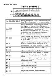
... indicates a Recall Channel; Flashes when a call is enabled. Appears while scanning is enabled. Appears when the optional scrambler board is received by the dealer. ■ Basic Panel Display w q e rt y u io!0!1!2 !3 q w e r t y u i o !0 !1 !2 !3 6 Displays the operating Group/ Channel number, the Group/ Channel name, and the transceiver status. Displays the operating group or channel number. P2 indicates a Priority 2 channel; Appears when signaling squelch is ON. Appears when Aux A is turned OFF. Appears...
... indicates a Recall Channel; Flashes when a call is enabled. Appears while scanning is enabled. Appears when the optional scrambler board is received by the dealer. ■ Basic Panel Display w q e rt y u io!0!1!2 !3 q w e r t y u i o !0 !1 !2 !3 6 Displays the operating Group/ Channel number, the Group/ Channel name, and the transceiver status. Displays the operating group or channel number. P2 indicates a Priority 2 channel; Appears when signaling squelch is ON. Appears when Aux A is turned OFF. Appears...
User Manual
Page 11
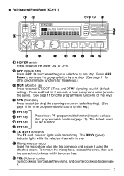
..., and DTMF signaling squelch (default setting). Press and hold for 2 seconds to hear background noise (unmute the audio). (See page 11 for other programmable functions for these PF (programmable function) keys to decrease it using the attached screw. To remove the microphone, release the screw, then turn the connector clockwise until it becomes free. !1 VOL (Volume) control Turn clockwise to increase the volume, and counterclockwise...
..., and DTMF signaling squelch (default setting). Press and hold for 2 seconds to hear background noise (unmute the audio). (See page 11 for other programmable functions for these PF (programmable function) keys to decrease it using the attached screw. To remove the microphone, release the screw, then turn the connector clockwise until it becomes free. !1 VOL (Volume) control Turn clockwise to increase the volume, and counterclockwise...
User Manual
Page 12
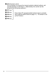
The default is set as No Function. !7 PF5 key 8 !2 CH (Channel) control Turn clockwise to increase the channel selection (default setting), and counterclockwise to decrease it. (Alternatively, this control can be programmed with group up/down.) !3 PF1 key !4 PF2 key !5 PF3 key !6 PF4 key Press these PF (programmable function) keys to activate their programmable functions {page 11}.
The default is set as No Function. !7 PF5 key 8 !2 CH (Channel) control Turn clockwise to increase the channel selection (default setting), and counterclockwise to decrease it. (Alternatively, this control can be programmed with group up/down.) !3 PF1 key !4 PF2 key !5 PF3 key !6 PF4 key Press these PF (programmable function) keys to activate their programmable functions {page 11}.
User Manual
Page 13
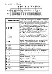
.... 9 Appears when audio output is in the scanning sequence if group scan has been set to "Multi" (please consult your dealer for setting the scan). Appears when Operator Selectable Tone is in the scanning sequence. P2 indicates a Priority 2 channel; RCL indicates a Recall Channel; Appears when the selected group is set to PA speaker. Appears when Aux C is turned OFF. Appears when signaling squelch is ON. Appears...
.... 9 Appears when audio output is in the scanning sequence if group scan has been set to "Multi" (please consult your dealer for setting the scan). Appears when Operator Selectable Tone is in the scanning sequence. P2 indicates a Priority 2 channel; RCL indicates a Recall Channel; Appears when the selected group is set to PA speaker. Appears when Aux C is turned OFF. Appears when signaling squelch is ON. Appears...
User Manual
Page 15
... 5 Direct) Press these keys to increase or decrease the channel number or group number (respectively). Press this key for 2 seconds to add the currently displayed group to have a function programmed onto a key (No Function). The group add icon disappears. To restore the original scanning sequence, turn the Aux A, Aux B, or Aux C output port (respectively) ON or OFF. Pressing and holding the key will change the number...
... 5 Direct) Press these keys to increase or decrease the channel number or group number (respectively). Press this key for 2 seconds to add the currently displayed group to have a function programmed onto a key (No Function). The group add icon disappears. To restore the original scanning sequence, turn the Aux A, Aux B, or Aux C output port (respectively) ON or OFF. Pressing and holding the key will change the number...
User Manual
Page 16
... 2Tone or DTMF signaling, horn alert will sound and HA (or HORN ALERT) appears on the display. DIM (Dimmer) Press this key to select the pre-programmed Home Channel. Press this key to another control head operator without transmitting over the air. The intercom can press the PTT switch to communicate to cancel QT/DQT and 2-Tone/DTMF signaling squelch. MON (Monitor...
... 2Tone or DTMF signaling, horn alert will sound and HA (or HORN ALERT) appears on the display. DIM (Dimmer) Press this key to select the pre-programmed Home Channel. Press this key to another control head operator without transmitting over the air. The intercom can press the PTT switch to communicate to cancel QT/DQT and 2-Tone/DTMF signaling squelch. MON (Monitor...
User Manual
Page 17
... automatically switch to use the CH control to the normal channel. When a signal is received while scanning, the scan will appear on the display. To enter carrier squelch scan, press the MON key while scan is less than a single channel. Press this key to be on the display. If Priority1 and Priority2 are programmed, the Priority1 channel takes precedence. ON HOOK requires the microphone to select the last called channel. A tone sounds...
... automatically switch to use the CH control to the normal channel. When a signal is received while scanning, the scan will appear on the display. To enter carrier squelch scan, press the MON key while scan is less than a single channel. Press this key to be on the display. If Priority1 and Priority2 are programmed, the Priority1 channel takes precedence. ON HOOK requires the microphone to select the last called channel. A tone sounds...
User Manual
Page 18
... the SP icon appears on the 3-digit display. When pressed, a tone sounds and MUTE appears on the display with the muted head number. However, all audio will be emitted from the other control head. When you want to talk to select the desired level. 3 Press the SQ key. You can manually adjust the squelch level using a repeater. TA (Talk Around) Press this...
... the SP icon appears on the 3-digit display. When pressed, a tone sounds and MUTE appears on the display with the muted head number. However, all audio will be emitted from the other control head. When you want to talk to select the desired level. 3 Press the SQ key. You can manually adjust the squelch level using a repeater. TA (Talk Around) Press this...
User Manual
Page 19
... Channel Down keys, or use the CH control (depending on the hanger when the call is finished. 15 If the channel is in use. BASIC OPERATIONS ■ Switching Power ON/ OFF Press the POWER switch to switch the transceiver ON (or OFF) • The display backlight illuminates when the power is switched ON. ■ Adjusting the Volume Turn the VOL control clockwise to increase the volume, and counterclockwise to receive. 4 Replace the microphone...
... Channel Down keys, or use the CH control (depending on the hanger when the call is finished. 15 If the channel is in use. BASIC OPERATIONS ■ Switching Power ON/ OFF Press the POWER switch to switch the transceiver ON (or OFF) • The display backlight illuminates when the power is switched ON. ■ Adjusting the Volume Turn the VOL control clockwise to increase the volume, and counterclockwise to receive. 4 Replace the microphone...

User Manual
Page 22
...; Operator Selectable Priority Channel You can press the PTT switch again within 0.5 seconds to automatically inhibit transmission after receiving the 2-Tone/ DTMF signal. 18 The transceiver will sound. When the transceiver receives a correct code, the CALL icon flashes. To set a Priority1 channel, press and hold the SCN key, then press the MON key 2 times. ■ 2-Tone/ DTMF Signaling 2-Tone/ DTMF signaling will only open the squelch when...
...; Operator Selectable Priority Channel You can press the PTT switch again within 0.5 seconds to automatically inhibit transmission after receiving the 2-Tone/ DTMF signal. 18 The transceiver will sound. When the transceiver receives a correct code, the CALL icon flashes. To set a Priority1 channel, press and hold the SCN key, then press the MON key 2 times. ■ 2-Tone/ DTMF Signaling 2-Tone/ DTMF signaling will only open the squelch when...
User Manual
Page 23
The timer resets when the ignition is disabled. If dead end is selected, when you turn OFF. Transmission is enabled. ■ Timed Power OFF This function requires an ignition-sense which must then rotate the CH control counterclockwise to change . For example, when turning the CH control clockwise, the channel number increases. If the radio receives a DBD reset code, the transceiver will roll over to its...
The timer resets when the ignition is disabled. If dead end is selected, when you turn OFF. Transmission is enabled. ■ Timed Power OFF This function requires an ignition-sense which must then rotate the CH control counterclockwise to change . For example, when turning the CH control clockwise, the channel number increases. If the radio receives a DBD reset code, the transceiver will roll over to its...


