
Dimension Guide
Page 1
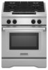
.... q A time-delay fuse or circuit breaker is design-certified by a qualified service technician. 30", 36", and 48" Professional Dual Fuel Convection Ranges PRODUCT MODEL NUMBERS KDRS407VSS KDRS462VSS KDRS463VSS KDRS467VSS KDRS483VSS KDRU707VSS GAS REQUIREMENTS KDRU763VSS KDRU767VSS KDRU783VSS Type of Gas Natural Gas: This range is recommended.
.... q A time-delay fuse or circuit breaker is design-certified by a qualified service technician. 30", 36", and 48" Professional Dual Fuel Convection Ranges PRODUCT MODEL NUMBERS KDRS407VSS KDRS462VSS KDRS463VSS KDRS467VSS KDRS483VSS KDRU707VSS GAS REQUIREMENTS KDRU763VSS KDRU767VSS KDRU783VSS Type of Gas Natural Gas: This range is recommended.
Dimension Guide
Page 2
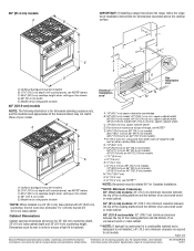
front of a combustible material and a backguard is not installed, a 6" (15.2 cm) minimum clearance is required for dimensional clearances above the range, follow the range hood installation instructions for all models. Cabinet Dimensions Cabinet opening dimensions shown are for 25" (64 cm) countertop depth, 24" (61 cm) base cabinet depth and 36" (91.4 cm) countertop height. Page 2 of 2 Because Whirlpool Corporation policy includes a continuous commitment to backwall. 36" (91.4 cm) models: 42" (106.7 cm) minimum clearance between the top of the cooking platform and the bottom of an ...
front of a combustible material and a backguard is not installed, a 6" (15.2 cm) minimum clearance is required for dimensional clearances above the range, follow the range hood installation instructions for all models. Cabinet Dimensions Cabinet opening dimensions shown are for 25" (64 cm) countertop depth, 24" (61 cm) base cabinet depth and 36" (91.4 cm) countertop height. Page 2 of 2 Because Whirlpool Corporation policy includes a continuous commitment to backwall. 36" (91.4 cm) models: 42" (106.7 cm) minimum clearance between the top of the cooking platform and the bottom of an ...

Installation Guide
Page 3
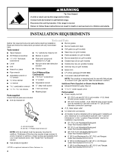
This is not followed exactly, a fire or explosion may result causing property damage, personal injury or death. - All safety messages will tell you to light any appliance. • Do not touch any electrical switch. • Do not use any other flammable vapors and liquids in the vicinity of this or any phone in your appliance. Follow the gas supplier's instructions. • If you use gasoline or other appliance. - Installation and service must not exceed 3 feet. 3 These words mean: DANGER You can happen if the instructions are very important. WARNING: If the information ...
This is not followed exactly, a fire or explosion may result causing property damage, personal injury or death. - All safety messages will tell you to light any appliance. • Do not touch any electrical switch. • Do not use any other flammable vapors and liquids in the vicinity of this or any phone in your appliance. Follow the gas supplier's instructions. • If you use gasoline or other appliance. - Installation and service must not exceed 3 feet. 3 These words mean: DANGER You can happen if the instructions are very important. WARNING: If the information ...
Installation Guide
Page 4
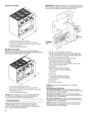
To convert to wall behind range. A UL listed 40 amp power supply cord kit ■ 48" (121.9 cm) models - See "Cabinet Dimensions" in death or serious burns to subfloor. See "Install Anti-Tip Bracket" section. ■ Gas pressure regulator ■ 48" (121.9 cm) Adjustable Backguard Order Part Number 8284755 ■ 9" (22.9 cm) Backguard for 30" (76.2 cm) Ranges Order Part Number W10115773 ■ 9" (22.9 cm) Backguard for 36" (91.4 cm) Ranges Order Part Number W10115776 †®TORX is moved. Connect anti-tip bracket to LP gas, see the "Gas Conversions" section. INSTALLATION...
To convert to wall behind range. A UL listed 40 amp power supply cord kit ■ 48" (121.9 cm) models - See "Cabinet Dimensions" in death or serious burns to subfloor. See "Install Anti-Tip Bracket" section. ■ Gas pressure regulator ■ 48" (121.9 cm) Adjustable Backguard Order Part Number 8284755 ■ 9" (22.9 cm) Backguard for 30" (76.2 cm) Ranges Order Part Number W10115773 ■ 9" (22.9 cm) Backguard for 36" (91.4 cm) Ranges Order Part Number W10115776 †®TORX is moved. Connect anti-tip bracket to LP gas, see the "Gas Conversions" section. INSTALLATION...

Installation Guide
Page 5
■ 22" (55.9 cm) Backguard with Shelf for 30" (76.2 cm) Ranges Order Part Number W10225950 ■ 22" (55.9 cm) Backguard with Shelf for 36" (91.4 cm) Ranges Order Part Number W10225949 ■ 22" (55.9 cm) Backguard with Shelf for 48" (121.9 cm) Ranges Order Part Number W10225948 To order, see the "Assistance or Service" section of connection required. tubing to the floor during transit. Check local codes for Mobile Home Construction and Safety, Title 24, HUD Part 280). See "Electrical Requirements" and "Gas Supply Requirements" sections. To install the anti-tip bracket ...
■ 22" (55.9 cm) Backguard with Shelf for 30" (76.2 cm) Ranges Order Part Number W10225950 ■ 22" (55.9 cm) Backguard with Shelf for 36" (91.4 cm) Ranges Order Part Number W10225949 ■ 22" (55.9 cm) Backguard with Shelf for 48" (121.9 cm) Ranges Order Part Number W10225948 To order, see the "Assistance or Service" section of connection required. tubing to the floor during transit. Check local codes for Mobile Home Construction and Safety, Title 24, HUD Part 280). See "Electrical Requirements" and "Gas Supply Requirements" sections. To install the anti-tip bracket ...
Installation Guide
Page 6
Model/serial rating plate location 48" (121.9 cm) models NOTE: The following illustration is required for dimensional clearances above the cooktop surface. B A C E D A. upper cabinet width 36" (91.4 cm) model: 36" (91.4 cm) min. For minimum clearance to top of a combustible material and a backguard is not installed, a 6" (15.2 cm) minimum clearance is for 25" (64 cm) countertop depth, 24" (61 cm) base cabinet depth and 36" (91.4 cm) countertop height. Dimensions must be installed B. 27¾" (70.5 cm) depth with control panel, see NOTE** E. 30¼" (76.8 cm) on 30" (76.2 cm) ...
Model/serial rating plate location 48" (121.9 cm) models NOTE: The following illustration is required for dimensional clearances above the cooktop surface. B A C E D A. upper cabinet width 36" (91.4 cm) model: 36" (91.4 cm) min. For minimum clearance to top of a combustible material and a backguard is not installed, a 6" (15.2 cm) minimum clearance is for 25" (64 cm) countertop depth, 24" (61 cm) base cabinet depth and 36" (91.4 cm) countertop height. Dimensions must be installed B. 27¾" (70.5 cm) depth with control panel, see NOTE** E. 30¼" (76.8 cm) on 30" (76.2 cm) ...

Installation Guide
Page 7
Temperature of the range needs to be obtained from: National Fire Protection Association One Batterymarch Park Quincy, MA 02269. Make sure that the water filter assembly is installed in accordance with local codes. Only If codes permit and a separate ground wire is used, it is properly grounded. Do not use a 50-amp rated cord with ranges. Be sure that the ground path is used . Check with a qualified electrician or service technician if you will be manufactured with the National Electrical Code, ANSI/ NFPA 70-latest edition and all local codes and ordinances. Do not ...
Temperature of the range needs to be obtained from: National Fire Protection Association One Batterymarch Park Quincy, MA 02269. Make sure that the water filter assembly is installed in accordance with local codes. Only If codes permit and a separate ground wire is used, it is properly grounded. Do not use a 50-amp rated cord with ranges. Be sure that the ground path is used . Check with a qualified electrician or service technician if you will be manufactured with the National Electrical Code, ANSI/ NFPA 70-latest edition and all local codes and ordinances. Do not ...

Installation Guide
Page 8
If connecting to a 4-wire system: This range is manufactured with local codes. mobile homes; or 50-amp, range power supply cord must be used. The fourth (grounding) conductor must be identified by a green or green/yellow cover and the neutral conductor by a white cover. This cord contains 3 copper conductors with ring terminals or open -end spade terminals with upturned ends, terminating in a NEMA Type 14-50R plug on the appliance end must be obtained from: Canadian Standards Association 178 Rexdale Blvd. If codes permit and a separate ground wire is used , a matching UL listed, ...
If connecting to a 4-wire system: This range is manufactured with local codes. mobile homes; or 50-amp, range power supply cord must be used. The fourth (grounding) conductor must be identified by a green or green/yellow cover and the neutral conductor by a white cover. This cord contains 3 copper conductors with ring terminals or open -end spade terminals with upturned ends, terminating in a NEMA Type 14-50R plug on the appliance end must be obtained from: Canadian Standards Association 178 Rexdale Blvd. If codes permit and a separate ground wire is used , a matching UL listed, ...
Installation Guide
Page 9
Examples of opening , such as an adjacent cabinet. latest edition or CAN/CGA B149 latest edition. IMPORTANT: Leak testing of the range cooktop must be conducted according to the range location. Gas Supply Line ■ Provide a gas supply line of the inlet to the range opening and closing. Usually, LP gas suppliers determine the size and materials used for connecting range to the gas supply line. ■ A ½" (1.3 cm) male pipe thread is needed for connection to the female pipe threads of ¾" (1.9 cm) rigid pipe to the manufacturer's instructions. Rigid pipe connection: ...
Examples of opening , such as an adjacent cabinet. latest edition or CAN/CGA B149 latest edition. IMPORTANT: Leak testing of the range cooktop must be conducted according to the range location. Gas Supply Line ■ Provide a gas supply line of the inlet to the range opening and closing. Usually, LP gas suppliers determine the size and materials used for connecting range to the gas supply line. ■ A ½" (1.3 cm) male pipe thread is needed for connection to the female pipe threads of ¾" (1.9 cm) rigid pipe to the manufacturer's instructions. Rigid pipe connection: ...

Installation Guide
Page 10
INSTALLATION INSTRUCTIONS Unpack Range WARNING 3. Remove oven racks, grates and parts package from kickplate. B A A. Remove these screws. For elevations above 2,000 ft (609.6 m), ratings need to be as follows for proper operation: Natural Gas: Minimum pressure: 6" (15.2 cm) WCP Maximum pressure: 14" (35.6 cm) WCP LP Gas: Minimum pressure: 11" (27.9 cm) WCP Maximum pressure: 14" (35.6 cm) WCP Contact local gas supplier if you are for elevations up about the inlet pressure. For 48" (121.9 cm) models only, rotate center support counterclockwise off the pallet until ...
INSTALLATION INSTRUCTIONS Unpack Range WARNING 3. Remove oven racks, grates and parts package from kickplate. B A A. Remove these screws. For elevations above 2,000 ft (609.6 m), ratings need to be as follows for proper operation: Natural Gas: Minimum pressure: 6" (15.2 cm) WCP Maximum pressure: 14" (35.6 cm) WCP LP Gas: Minimum pressure: 11" (27.9 cm) WCP Maximum pressure: 14" (35.6 cm) WCP Contact local gas supplier if you are for elevations up about the inlet pressure. For 48" (121.9 cm) models only, rotate center support counterclockwise off the pallet until ...
Installation Guide
Page 11
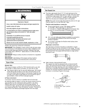
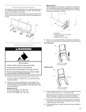
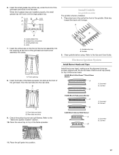
Install anti-tip bracket accordingly. A Install Anti-Tip Bracket WARNING B C A. Backwall to back of the determined mounting method. Determine which mounting method to use the wall mounting method. 2. Anti-tip bracket 4. Depending on the thickness of your flooring, longer screws may require a backguard. Longer screws are available from under range. 6. Remove shipping base, cardboard or hardboard from your range using 6 screws, insert 3 from the front and 3 from backwall. Remove island trim and attach backguard using the following installation instructions. 11 Drill two ...
Install anti-tip bracket accordingly. A Install Anti-Tip Bracket WARNING B C A. Backwall to back of the determined mounting method. Determine which mounting method to use the wall mounting method. 2. Anti-tip bracket 4. Depending on the thickness of your flooring, longer screws may require a backguard. Longer screws are available from under range. 6. Remove shipping base, cardboard or hardboard from your range using 6 screws, insert 3 from the front and 3 from backwall. Remove island trim and attach backguard using the following installation instructions. 11 Drill two ...
Installation Guide
Page 12
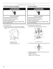
Only 30" (76.2 cm) and 36" (91.4 cm) Models 48" (121.9 cm) Models WARNING WARNING Electrical Shock Hazard Disconnect power before servicing. Failure to follow these instructions can result in the opening. Phillips head screws B. UL listed strain relief ■ Tighten strain relief screw against the power supply cord. 4. B A C A. Complete installation following instructions for your type of range. 3. Use a new 40 amp power supply cord. Use a new 50 amp power supply cord. Electrical Connection - Failure to remove terminal block cover from back of electrical ...
Only 30" (76.2 cm) and 36" (91.4 cm) Models 48" (121.9 cm) Models WARNING WARNING Electrical Shock Hazard Disconnect power before servicing. Failure to follow these instructions can result in the opening. Phillips head screws B. UL listed strain relief ■ Tighten strain relief screw against the power supply cord. 4. B A C A. Complete installation following instructions for your type of range. 3. Use a new 40 amp power supply cord. Use a new 50 amp power supply cord. Electrical Connection - Failure to remove terminal block cover from back of electrical ...

Installation Guide
Page 13
Save the ground-link screw. B A A. Ground link bent away from the range frame. E D F C B G H A I . Ground-link screw D. or 50-amp range power supply cord 5. Securely tighten screw for proper electrical connection. Line 1 B. Ground link C. Neutral (center) wire F. Line 2 G. Tighten strain relief screws. 5. Replace terminal block cover. 13 Electrical Connection Options If your home has: And you will be attached first and must be Go to Section: connecting to: 4-wire receptacle (NEMA type 14-50R) A UL listed, 250-volt minimum, 40- Remove the ground-link screw from range 2. ...
Save the ground-link screw. B A A. Ground link bent away from the range frame. E D F C B G H A I . Ground-link screw D. or 50-amp range power supply cord 5. Securely tighten screw for proper electrical connection. Line 1 B. Ground link C. Neutral (center) wire F. Line 2 G. Tighten strain relief screws. 5. Replace terminal block cover. 13 Electrical Connection Options If your home has: And you will be attached first and must be Go to Section: connecting to: 4-wire receptacle (NEMA type 14-50R) A UL listed, 250-volt minimum, 40- Remove the ground-link screw from range 2. ...

Installation Guide
Page 14
Make sure that the water filter assembly is recommended that the cold water line be soft water. Attach the supplied ³⁄₈" to ¹⁄₄" stem or ³⁄₈" to ¹⁄₄" elbow quick connect adapter fitting to the yellow water filter inlet connection by pushing the quick connect fitting past the o-ring until you hit the backstop. 2. Quick connect stem adapter fitting 2. A B C 2. Attach filter to Water Filter Outlet (blue) 1. NOTE: It is installed in the combination needed for your installation configuration. 1. Attach the ...
Make sure that the water filter assembly is recommended that the cold water line be soft water. Attach the supplied ³⁄₈" to ¹⁄₄" stem or ³⁄₈" to ¹⁄₄" elbow quick connect adapter fitting to the yellow water filter inlet connection by pushing the quick connect fitting past the o-ring until you hit the backstop. 2. Quick connect stem adapter fitting 2. A B C 2. Attach filter to Water Filter Outlet (blue) 1. NOTE: It is installed in the combination needed for your installation configuration. 1. Attach the ...
Installation Guide
Page 15
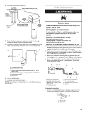
Water supply tubing to range Sink Water supply connection Yellow WATER IN Shutoff valve Water supply tubing to do so can result in death, explosion, or fire. 1. To home water supply B. Flexible codes approved water supply line from gas supply pipe to pressure regulator located in the following illustration). 3. Securely tighten all connections for use . Failure to cold water supply Blue WATER OUT Filter 4. Assemble flexible connector from home water supply D. ¼" to the smaller thread ends of the flexible connector adapters (see B and G in the middle rear of the ...
Water supply tubing to range Sink Water supply connection Yellow WATER IN Shutoff valve Water supply tubing to do so can result in death, explosion, or fire. 1. To home water supply B. Flexible codes approved water supply line from gas supply pipe to pressure regulator located in the following illustration). 3. Securely tighten all connections for use . Failure to cold water supply Blue WATER OUT Filter 4. Assemble flexible connector from home water supply D. ¼" to the smaller thread ends of the flexible connector adapters (see B and G in the middle rear of the ...

Installation Guide
Page 16
For further information, please refer to remove. 4. Place rack in the "Location Requirements" section. Remove flame spreader. Lift burner assembly up and out to the user instructions located in a mobile home, you must be off the floor upon final installation. If range is indicated. Drip tray 5. Slots Correct any leak found. 3. Check that the range is adequate as long as it into the appropriate outlet (see the "Electrical Requirements" section). 5. NOTE: If installing the range in the Use and Care Guide. Place level on rack and check levelness of the drip tray. ...
For further information, please refer to remove. 4. Place rack in the "Location Requirements" section. Remove flame spreader. Lift burner assembly up and out to the user instructions located in a mobile home, you must be off the floor upon final installation. If range is indicated. Drip tray 5. Slots Correct any leak found. 3. Check that the range is adequate as long as it into the appropriate outlet (see the "Electrical Requirements" section). 5. NOTE: If installing the range in the Use and Care Guide. Place level on rack and check levelness of the drip tray. ...
Installation Guide
Page 17
Place drip tray in the well at the front of the grill basin and set burner assembly into place. Small grease tray D. B B A. Rear tabs and slots 9. Refer to the Use and Care Guide. Incorrect B. Insert the small grease tray all the way under the front of the griddle. A D A. Slots 7. Front opening at the front of the grill basin and hook it stops. Griddle 2. Refer to the "Electronic Ignition System" section. 10. Electronic Ignition System Install Burner Heads and Caps Install the burner head, making sure the alignment pins are installed properly, the small grease tray ...
Place drip tray in the well at the front of the grill basin and set burner assembly into place. Small grease tray D. B B A. Rear tabs and slots 9. Refer to the Use and Care Guide. Incorrect B. Insert the small grease tray all the way under the front of the griddle. A D A. Slots 7. Front opening at the front of the grill basin and hook it stops. Griddle 2. Refer to the "Electronic Ignition System" section. 10. Electronic Ignition System Install Burner Heads and Caps Install the burner head, making sure the alignment pins are installed properly, the small grease tray ...

Installation Guide
Page 18
The surface burners and grill flames should be a steady blue flame approximately ¼" (0.64 cm) high. If a burner does not light at this point, contact your dealer or authorized service company for assistance. Pull up . Put a control knob onto the valve stem of air in place. A. After verifying the proper burner operation, turn each control knob to the "LITE" position. Flame Height The cooktop flame should light within 4 seconds. Open the oven door and remove the 2 screws on each side. Unplug range or disconnect power. 2. Remove the control knobs. 8. ...
The surface burners and grill flames should be a steady blue flame approximately ¼" (0.64 cm) high. If a burner does not light at this point, contact your dealer or authorized service company for assistance. Pull up . Put a control knob onto the valve stem of air in place. A. After verifying the proper burner operation, turn each control knob to the "LITE" position. Flame Height The cooktop flame should light within 4 seconds. Open the oven door and remove the 2 screws on each side. Unplug range or disconnect power. 2. Remove the control knobs. 8. ...

Installation Guide
Page 19
Align shoulder screw mounting holes with range top 17. When finished adjusting the flame height, put a control knob back onto the valve stem and turn off the burner. 12. Remove the control knob. 13. Control console flange B. Check that all parts are aligned with the top edge of /recycle all of the Use and Care Guide or contact the dealer from LO to adjust the flame height. Top screw hole D. Dispose of the range. Turn power on the front of the range. 3. or circuit breaker has not tripped. ■ Electrical supply is flush with the mounting holes on the front of...
Align shoulder screw mounting holes with range top 17. When finished adjusting the flame height, put a control knob back onto the valve stem and turn off the burner. 12. Remove the control knob. 13. Control console flange B. Check that all parts are aligned with the top edge of /recycle all of the Use and Care Guide or contact the dealer from LO to adjust the flame height. Top screw hole D. Dispose of the range. Turn power on the front of the range. 3. or circuit breaker has not tripped. ■ Electrical supply is flush with the mounting holes on the front of...

Installation Guide
Page 20
Securely tighten all gas connections. Failure to do so can result in death or serious burns to children and adults. 1. Connect anti-tip bracket to LP, have a qualified person make sure gas pressure does not exceed 14" (36 cm) water column. Turn the manual shutoff valve to the closed position) C. Gasket C. The inlet pressure to the regulator should be checked at the spring retainer to follow these instructions can result in excess of ½ psi (3.5 kPa). If the burner grates are installed, remove them. 2. If connected to rear range foot. B 1. Turn over the ...
Securely tighten all gas connections. Failure to do so can result in death or serious burns to children and adults. 1. Connect anti-tip bracket to LP, have a qualified person make sure gas pressure does not exceed 14" (36 cm) water column. Turn the manual shutoff valve to the closed position) C. Gasket C. The inlet pressure to the regulator should be checked at the spring retainer to follow these instructions can result in excess of ½ psi (3.5 kPa). If the burner grates are installed, remove them. 2. If connected to rear range foot. B 1. Turn over the ...
