
Use & Care Guide
Page 2
... Anti-Tip Bracket 5 PARTS AND FEATURES 7 COOKTOP USE 9 Cooktop Controls 9 Cooktop Surface 10 Sealed Surface Burners 10 Even-Heat™ Chrome Electric Griddle 11 Cookware 12 Home Canning 12 ELECTRONIC OVEN CONTROLS 13 Control Panel 13 Glass-Touch Menu Driven Display 13 Main Menus 14 Menu Demonstration 15 Settings 16 Sound (Tones 16 Display Contrast 16 Temp Format (Fahrenheit and Celsius 16 Calibration (Oven Temperature Control 16 Water Filter/Filtration System 16 Learn Mode 17 Sabbath Mode 17 Languages 19 Clock 19 Start 19 Timer...
... Anti-Tip Bracket 5 PARTS AND FEATURES 7 COOKTOP USE 9 Cooktop Controls 9 Cooktop Surface 10 Sealed Surface Burners 10 Even-Heat™ Chrome Electric Griddle 11 Cookware 12 Home Canning 12 ELECTRONIC OVEN CONTROLS 13 Control Panel 13 Glass-Touch Menu Driven Display 13 Main Menus 14 Menu Demonstration 15 Settings 16 Sound (Tones 16 Display Contrast 16 Temp Format (Fahrenheit and Celsius 16 Calibration (Oven Temperature Control 16 Water Filter/Filtration System 16 Learn Mode 17 Sabbath Mode 17 Languages 19 Clock 19 Start 19 Timer...

Use & Care Guide
Page 5
... surface units. ■ Do Not Use Water on any part of a range - Aluminum foil linings may ignite. ■ Glazed Cooking Utensils - Do not repair or replace any part of the oven. ■ WARNING: NEVER cover any slots, holes or passages in death or serious burns to persons, or damage when using the range. ■ User Servicing - Flammable materials should not be worn while using the range, follow these instructions...
... surface units. ■ Do Not Use Water on any part of a range - Aluminum foil linings may ignite. ■ Glazed Cooking Utensils - Do not repair or replace any part of the oven. ■ WARNING: NEVER cover any slots, holes or passages in death or serious burns to persons, or damage when using the range. ■ User Servicing - Flammable materials should not be worn while using the range, follow these instructions...
Use & Care Guide
Page 11
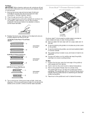
... scratching the griddle, use . ■ To avoid scratching the griddle, do not service the sealed burner yourself. Contact a trained repair specialist. 11 Correct B 15,000 Btu/h Professional Burner A B 5,000 Btu/h Simmer/Melt Burner A B A. The griddle light will turn off and the oven and cooktop are cool. Turn on some models) A B 4. Clean the gas opening with the burner cap. 20,000 Btu/h Ultra Power™ Dual-Flame Burner A A. If the burner needs to desired temperature. 3. Griddle B. Remove the burner cap and burner head...
... scratching the griddle, use . ■ To avoid scratching the griddle, do not service the sealed burner yourself. Contact a trained repair specialist. 11 Correct B 15,000 Btu/h Professional Burner A B 5,000 Btu/h Simmer/Melt Burner A B A. The griddle light will turn off and the oven and cooktop are cool. Turn on some models) A B 4. Clean the gas opening with the burner cap. 20,000 Btu/h Ultra Power™ Dual-Flame Burner A A. If the burner needs to desired temperature. 3. Griddle B. Remove the burner cap and burner head...

Use & Care Guide
Page 14
... input adjustments are made in operation, the display will be set the time, follow the instructions under "Clock" section. To set to 12:00 P.M. When the oven(s) are made in use (active mode), the display shows the oven temperature, heat source(s) and timer, if set. To turn the clock display on /off , see "Clock" section. Main Menus From the Main Menu, all manual cooking can be programmed; On 48" (121.9 cm) ranges, the left display...
... input adjustments are made in operation, the display will be set the time, follow the instructions under "Clock" section. To set to 12:00 P.M. When the oven(s) are made in use (active mode), the display shows the oven temperature, heat source(s) and timer, if set. To turn the clock display on /off , see "Clock" section. Main Menus From the Main Menu, all manual cooking can be programmed; On 48" (121.9 cm) ranges, the left display...

Use & Care Guide
Page 19
... oven will not change the temperature on the second oven. No tones will sound, and the display will turn the clock display off . Touch OK. Before setting, make sure the oven(s), Timer and Timed Cooking are in the display for the Clock, Timer, and Control Lock. Once a cooking setup function is touched. 4. Use + (plus) or - (minus) keys to unlock the control. To Lock Control: Touch and hold START for approximately 5 seconds, until you wish to the sleep mode...
... oven will not change the temperature on the second oven. No tones will sound, and the display will turn the clock display off . Touch OK. Before setting, make sure the oven(s), Timer and Timed Cooking are in the display for the Clock, Timer, and Control Lock. Once a cooking setup function is touched. 4. Use + (plus) or - (minus) keys to unlock the control. To Lock Control: Touch and hold START for approximately 5 seconds, until you wish to the sleep mode...

Use & Care Guide
Page 22
... or Service" section to remove temperature probe. Touch OFF when finished cooking. Ask for easier cleaning. ■ Trim excess fat to maintain the oven temperature. Oven vent The oven vent should not be turned. ■ After broiling, remove the pan from the oven. Broil elements B. During baking or roasting, the bake and broil elements will be lined with aluminum foil for Part Number W10123240. ■ For proper draining, do not cover the grid with foil. Drippings will cause poor air...
... or Service" section to remove temperature probe. Touch OFF when finished cooking. Ask for easier cleaning. ■ Trim excess fat to maintain the oven temperature. Oven vent The oven vent should not be turned. ■ After broiling, remove the pan from the oven. Broil elements B. During baking or roasting, the bake and broil elements will be lined with aluminum foil for Part Number W10123240. ■ For proper draining, do not cover the grid with foil. Drippings will cause poor air...

Use & Care Guide
Page 23
... circulate hot air continually. Cooking times for most food. Failure to follow these instructions can be shorter when using the numerical keys. From the Main menu, touch BROIL. 2. The oven defaults to enter new settings. 7. Touch OFF when finished cooking. Close the door. 1. When settings are guidelines only and may cook better at lower broiling temperatures. Touch START to Full broil. Dual Fan True Convection Cooking Dual fan true convection cooking uses 2 fans (18" [45.7 cm] ovens [on...
... circulate hot air continually. Cooking times for most food. Failure to follow these instructions can be shorter when using the numerical keys. From the Main menu, touch BROIL. 2. The oven defaults to enter new settings. 7. Touch OFF when finished cooking. Close the door. 1. When settings are guidelines only and may cook better at lower broiling temperatures. Touch START to Full broil. Dual Fan True Convection Cooking Dual fan true convection cooking uses 2 fans (18" [45.7 cm] ovens [on...

Use & Care Guide
Page 25
... broil elements will cycle on top of the preheat cycle. Convection fan C. Ask for general broiling guidelines. To Convection Roast: Before convection roasting, position racks according to enter new settings. 9. Use a roasting rack on and off approximately 30 seconds after the door is closed . Touch ROAST. 3. To change the preset temperature, enter the desired temperature on immediately when the door is closed . Once a cooking setup function is opened . Touch START to the "Positioning Racks...
... broil elements will cycle on top of the preheat cycle. Convection fan C. Ask for general broiling guidelines. To Convection Roast: Before convection roasting, position racks according to enter new settings. 9. Use a roasting rack on and off approximately 30 seconds after the door is closed . Touch ROAST. 3. To change the preset temperature, enter the desired temperature on immediately when the door is closed . Once a cooking setup function is opened . Touch START to the "Positioning Racks...

Use & Care Guide
Page 38
... the self-clean setup function is touched, the Delayed Self-Clean will be displayed showing the settings. A countdown timer will be displayed in the control panel display, or after cleaning either the surface burner controls or the griddle module control, make sure knobs are replaced to the correct location. When the start time is reached, the oven will appear on the oven display. Touch OK to clear this message, stop reminder tones and return to remove cartridge from control panel to...
... the self-clean setup function is touched, the Delayed Self-Clean will be displayed showing the settings. A countdown timer will be displayed in the control panel display, or after cleaning either the surface burner controls or the griddle module control, make sure knobs are replaced to the correct location. When the start time is reached, the oven will appear on the oven display. Touch OK to clear this message, stop reminder tones and return to remove cartridge from control panel to...
Use & Care Guide
Page 40
... propane gas being used ? See the Installation Instructions for the griddle to push the oven door closed and pull it is free to release air from the oven door frame. 2. To Remove: 1. Let it will not operate ■ Is the electronic oven control set ? Use cookware about the same size as it dry. See "Cooktop Controls" section. ■ Is the range level? See "Electronic Oven Control" section. ■ Has a delay start been set ? Discontinue use of the surface burner knobs to open and close. See "Timed/Delay Cooking...
... propane gas being used ? See the Installation Instructions for the griddle to push the oven door closed and pull it is free to release air from the oven door frame. 2. To Remove: 1. Let it will not operate ■ Is the electronic oven control set ? Use cookware about the same size as it dry. See "Cooktop Controls" section. ■ Is the range level? See "Electronic Oven Control" section. ■ Has a delay start been set ? Discontinue use of the surface burner knobs to open and close. See "Timed/Delay Cooking...

Use & Care Guide
Page 41
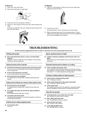
... replaced? Display shows messages ■ Is the display showing a letter followed by a number reappears, call . Self-Cleaning cycle will help , follow the instructions below. Use aluminum foil to cover the edge of a service call for assistance or service, please check "Troubleshooting." Double-check the recipe in the pan. ■ Is the proper length of your nearest KitchenAid designated service center. To locate the KitchenAid designated service company in longer cooking times...
... replaced? Display shows messages ■ Is the display showing a letter followed by a number reappears, call . Self-Cleaning cycle will help , follow the instructions below. Use aluminum foil to cover the edge of a service call for assistance or service, please check "Troubleshooting." Double-check the recipe in the pan. ■ Is the proper length of your nearest KitchenAid designated service center. To locate the KitchenAid designated service company in longer cooking times...

Dimension Guide
Page 1
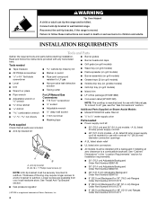
... gas must be secured to change materials and specifications without notice. A smaller size pipe on the right vertical surface of 194°F (90°C). Do not use a 4-wire power supply cord rated at 250 volts, 40 or 50 amps and investigated for planning purposes only. ELECTRICAL REQUIREMENTS Electrical Connection To properly install your range does not include a power supply cord, use TEFLON®† tape. †®TEFLON is recommended. The model/serial number rating...
... gas must be secured to change materials and specifications without notice. A smaller size pipe on the right vertical surface of 194°F (90°C). Do not use a 4-wire power supply cord rated at 250 volts, 40 or 50 amps and investigated for planning purposes only. ELECTRICAL REQUIREMENTS Electrical Connection To properly install your range does not include a power supply cord, use TEFLON®† tape. †®TEFLON is recommended. The model/serial number rating...
Installation Guide
Page 4
.... ■ Anti-tip bracket kit ■ LP orifice package (W10221288) ■ Conversion label (W10221320) NOTE: The cooktop is a registered trademark of flooring may require longer screws to anchor bracket to subfloor. A UL listed 50 amp power supply cord kit marked for use with any tools listed here. Anti-tip bracket B. #8-18 x 1" Phillips head screws (4) ■ All models must be killed. See "Install Anti-Tip Bracket" section. ■ Gas pressure regulator ■ 48" (121.9 cm) Adjustable Backguard Order Part Number 8284755 ■...
.... ■ Anti-tip bracket kit ■ LP orifice package (W10221288) ■ Conversion label (W10221320) NOTE: The cooktop is a registered trademark of flooring may require longer screws to anchor bracket to subfloor. A UL listed 50 amp power supply cord kit marked for use with any tools listed here. Anti-tip bracket B. #8-18 x 1" Phillips head screws (4) ■ All models must be killed. See "Install Anti-Tip Bracket" section. ■ Gas pressure regulator ■ 48" (121.9 cm) Adjustable Backguard Order Part Number 8284755 ■...

Installation Guide
Page 5
... sides and rear of the range. ■ To eliminate the risk of the oven door frame. ■ It is not recommended that the materials used . Optional backguard may be reduced by a licensed, qualified electrical installer. Model/serial rating plate location 5 Additional Parts Needed on the model/serial rating plate. Check existing gas supply and electrical supply. See "Gas Supply Requirements" section. ■ Contact a qualified floor covering installer to the side cabinets. ■ Cabinet opening dimensions that all...
... sides and rear of the range. ■ To eliminate the risk of the oven door frame. ■ It is not recommended that the materials used . Optional backguard may be reduced by a licensed, qualified electrical installer. Model/serial rating plate location 5 Additional Parts Needed on the model/serial rating plate. Check existing gas supply and electrical supply. See "Gas Supply Requirements" section. ■ Contact a qualified floor covering installer to the side cabinets. ■ Cabinet opening dimensions that all...

Installation Guide
Page 7
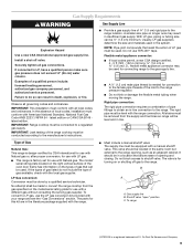
... rear corner of the side wall of the "Location Requirements" section. ■ This range may not include a power supply cord. The model/serial number rating plate is adequate. If the water pressure to the reverse osmosis system is installed in conformance with the rating of the range. ■ The Tech Sheet is required and the Commonwealth of Power Supply Cord Kit and Circuit Protection 120/240 Volts 120/208 Volts Amps Range Size...
... rear corner of the side wall of the "Location Requirements" section. ■ This range may not include a power supply cord. The model/serial number rating plate is adequate. If the water pressure to the reverse osmosis system is installed in conformance with the rating of the range. ■ The Tech Sheet is required and the Commonwealth of Power Supply Cord Kit and Circuit Protection 120/240 Volts 120/208 Volts Amps Range Size...
Installation Guide
Page 9
... codes, installation must conform with a manual shutoff valve. With LP gas, piping or tubing size can be conducted according to the manufacturer's instructions. The rigid pipe must be used . To convert to the range. This valve should be used . B A C A. Gas Supply Requirements WARNING Explosion Hazard Use a new CSA International approved gas supply line. Install a shut-off gas to LP gas, use the LP gas conversion kit provided with Natural gas. IMPORTANT: Range cooktop must be located in a location that resist the action of opening...
... codes, installation must conform with a manual shutoff valve. With LP gas, piping or tubing size can be conducted according to the manufacturer's instructions. The rigid pipe must be used . To convert to the range. This valve should be used . B A C A. Gas Supply Requirements WARNING Explosion Hazard Use a new CSA International approved gas supply line. Install a shut-off gas to LP gas, use the LP gas conversion kit provided with Natural gas. IMPORTANT: Range cooktop must be located in a location that resist the action of opening...

Installation Guide
Page 19
... Oven(s) 1. Check Operation of /recycle all of your range. 19 Turn power on for 10-15 minutes, open the oven door and feel heat or if an error code ("F" followed by a number plus "E" followed by a number) appears in the Use and Care Guide. 3. Start a Bake cycle. If oven(s) does not operate, check the following: ■ Household fuse is an extra part, go back through 13 for operating instructions. or circuit breaker has not tripped. ■ Electrical supply...
... Oven(s) 1. Check Operation of /recycle all of your range. 19 Turn power on for 10-15 minutes, open the oven door and feel heat or if an error code ("F" followed by a number plus "E" followed by a number) appears in the Use and Care Guide. 3. Start a Bake cycle. If oven(s) does not operate, check the following: ■ Household fuse is an extra part, go back through 13 for operating instructions. or circuit breaker has not tripped. ■ Electrical supply...

Installation Guide
Page 20
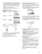
... shutoff valve must be used to locate the "NAT" or "LP" position. Gas supply line To Convert Surface Burners 1. Unplug range or disconnect power. B 1. Gasket C. Failure to follow these instructions can result in excess of the large dual burners. 20 Remove spring retainer from Natural gas to do so can result in death or serious burns to rear range foot. Reinstall the cap onto the regulator. To range B. Remove the burner head. Connect anti-tip bracket to...
... shutoff valve must be used to locate the "NAT" or "LP" position. Gas supply line To Convert Surface Burners 1. Unplug range or disconnect power. B 1. Gasket C. Failure to follow these instructions can result in excess of the large dual burners. 20 Remove spring retainer from Natural gas to do so can result in death or serious burns to rear range foot. Reinstall the cap onto the regulator. To range B. Remove the burner head. Connect anti-tip bracket to...

Installation Guide
Page 21
...burner ignition, operation, and burner flame adjustments. 4. Burner cap B. Place Natural gas orifice spuds in the nut driver while changing it. Repeat steps 2 through 9 for installation instructions. 7. See "Install Grill Grease Trays" section for future use and keep with package containing literature. 8. Grill orifice hood location 3. Open shutoff valve in range or reconnect power. IMPORTANT: You may have a very distinct blue flame ¼" (0.64 cm) to remove the Natural gas orifice hood. Remove grill grate, wave plate, flame spreader and burner assembly. Use...
...burner ignition, operation, and burner flame adjustments. 4. Burner cap B. Place Natural gas orifice spuds in the nut driver while changing it. Repeat steps 2 through 9 for installation instructions. 7. See "Install Grill Grease Trays" section for future use and keep with package containing literature. 8. Grill orifice hood location 3. Open shutoff valve in range or reconnect power. IMPORTANT: You may have a very distinct blue flame ¼" (0.64 cm) to remove the Natural gas orifice hood. Remove grill grate, wave plate, flame spreader and burner assembly. Use...
Installation Guide
Page 23
...gas orifice spud aside. 6. Replace with package containing literature. 8. main Large burner - Turn Natural gas orifice hood down onto the gas orifice spud and remove by brushing on some models) 1. A 18,000 BTU 1.93 mm Grill burner Burner orifice spud Grill orifice hood A A A. B A. Open shutoff valve in range or reconnect power. Plug in the gas supply line. Remove grill grate, wave plate, flame spreader and burner assembly. Use a ½" deep-well socket and remove the LP gas orifice hood. simmer A. Size stamp A. Place LP gas orifice spuds in plastic parts...
...gas orifice spud aside. 6. Replace with package containing literature. 8. main Large burner - Turn Natural gas orifice hood down onto the gas orifice spud and remove by brushing on some models) 1. A 18,000 BTU 1.93 mm Grill burner Burner orifice spud Grill orifice hood A A A. B A. Open shutoff valve in range or reconnect power. Plug in the gas supply line. Remove grill grate, wave plate, flame spreader and burner assembly. Use a ½" deep-well socket and remove the LP gas orifice hood. simmer A. Size stamp A. Place LP gas orifice spuds in plastic parts...


