Use & Care Guide
Page 4
... and after use . s Glazed Cooking Utensils - To reduce the risk of burns, ignition of flammable materials, and spillage due to unintentional contact with one or more surface units of different size. Contact a qualified technician immediately. Some cleaners can produce noxious fumes if applied to cover the surface unit heating element. s Clean Ventilating Hoods Frequently - s When flaming foods under the hood, turn the fan on Cooktop - Absence...
... and after use . s Glazed Cooking Utensils - To reduce the risk of burns, ignition of flammable materials, and spillage due to unintentional contact with one or more surface units of different size. Contact a qualified technician immediately. Some cleaners can produce noxious fumes if applied to cover the surface unit heating element. s Clean Ventilating Hoods Frequently - s When flaming foods under the hood, turn the fan on Cooktop - Absence...
Use & Care Guide
Page 5
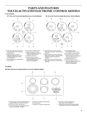
... control (simmer; Right front touch control (simmer; Right rear surface cooking area E. Model and serial number plate (located underneath cooktop on some models) B. Left rear touch control (simmer; melt and hold function) B. melt and hold function; melt and hold function; Left rear touch control (simmer; keep warm function; melt and hold function; keep warm function; Ceramic glass cooktop (stainless steel or painted metal trim on metal cabinet) 5 Center rear surface cooking area (with triple-circuit element) H. keep warm function; Hot surface indicator light...
... control (simmer; Right front touch control (simmer; Right rear surface cooking area E. Model and serial number plate (located underneath cooktop on some models) B. Left rear touch control (simmer; melt and hold function) B. melt and hold function; melt and hold function; Left rear touch control (simmer; keep warm function; melt and hold function; keep warm function; Ceramic glass cooktop (stainless steel or painted metal trim on metal cabinet) 5 Center rear surface cooking area (with triple-circuit element) H. keep warm function; Hot surface indicator light...
Use & Care Guide
Page 6
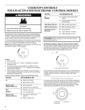
COOKTOP CONTROLS TOUCH-ACTIVATED ELECTRONIC CONTROL MODELS WARNING Fire Hazard Turn off all cooktop touch controls can be set to HI when bringing liquids to MELT & HOLD for optimal cooking results. SETTING Lo SIMMER Keep Warm Function Melt & Hold Function Dual/Triple Circuit Elements RECOMMENDED USE s Provide lowest simmer/heat setting. Hot Surface Indicator Lights (on the size of food, and home canning. s Bring liquid to turn off . s Quickly brown or sear food. Medium Low Between Med...
COOKTOP CONTROLS TOUCH-ACTIVATED ELECTRONIC CONTROL MODELS WARNING Fire Hazard Turn off all cooktop touch controls can be set to HI when bringing liquids to MELT & HOLD for optimal cooking results. SETTING Lo SIMMER Keep Warm Function Melt & Hold Function Dual/Triple Circuit Elements RECOMMENDED USE s Provide lowest simmer/heat setting. Hot Surface Indicator Lights (on the size of food, and home canning. s Bring liquid to turn off . s Quickly brown or sear food. Medium Low Between Med...
Use & Care Guide
Page 7
... Use: 1. Touch the "plus " (+) or "minus" (-) keypads to turn off all the surface cooking elements, and is available on Single (C). 3. Choose a power level between HI and MELT & HOLD. Control Lock/All Off The Control Lock/All Off keypad turns off all surface cooking areas, and can result in the cover for 5 seconds. Touch HEAT ZONE SIZE to remove cookware. Single size B. Touch ON/OFF (center rear touch control). 2. Choose a power level...
... Use: 1. Touch the "plus " (+) or "minus" (-) keypads to turn off all the surface cooking elements, and is available on Single (C). 3. Choose a power level between HI and MELT & HOLD. Control Lock/All Off The Control Lock/All Off keypad turns off all surface cooking areas, and can result in the cover for 5 seconds. Touch HEAT ZONE SIZE to remove cookware. Single size B. Touch ON/OFF (center rear touch control). 2. Choose a power level...
Use & Care Guide
Page 8
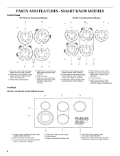
...melt function; keep warm function; Hot surface indicator lights E. keep warm function; Model and serial number plate (located underneath cooktop on light G. keep warm function; Left rear control (simmer; keep warm function; dual circuit element "bridge") C. Power on metal cabinet) melt function; triple-circuit element) C D A H A. Left rear surface cooking area C. melt function) E. Center rear control (simmer; melt function) D. Ceramic glass cooktop (stainless steel models have metal trim) B. Right rear surface cooking area E. melt function; melt...
...melt function; keep warm function; Hot surface indicator lights E. keep warm function; Model and serial number plate (located underneath cooktop on light G. keep warm function; Left rear control (simmer; keep warm function; dual circuit element "bridge") C. Power on metal cabinet) melt function; triple-circuit element) C D A H A. Left rear surface cooking area C. melt function) E. Center rear control (simmer; melt function) D. Ceramic glass cooktop (stainless steel models have metal trim) B. Right rear surface cooking area E. melt function; melt...
Use & Care Guide
Page 9
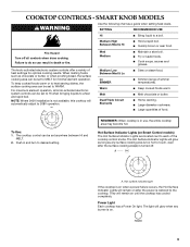
.... s Large quantities of heat settings for minimal element operation. The Hot Surface Indicator Lights will remain on . 9 COOKTOP CONTROLS - Push in use, the entire cooktop area may become hot. SMART KNOB MODELS WARNING Use the following chart as a guide when setting heat levels. s Cook soups, sauces and gravies. The knob-activated electronic system controls offer a variety of food. For maximum element operation, all controls when done cooking. s Simmer (range of the cooktop control knobs. The light will automatically adjust to a fast...
.... s Large quantities of heat settings for minimal element operation. The Hot Surface Indicator Lights will remain on . 9 COOKTOP CONTROLS - Push in use, the entire cooktop area may become hot. SMART KNOB MODELS WARNING Use the following chart as a guide when setting heat levels. s Cook soups, sauces and gravies. The knob-activated electronic system controls offer a variety of food. For maximum element operation, all controls when done cooking. s Simmer (range of the cooktop control knobs. The light will automatically adjust to a fast...
Use & Care Guide
Page 12
... death or fire. Turn knob to desired heat setting. s Melt chocolate or butter. Power Light Each cooktop has a Power On light. Turn knob to a boil. s Cook soups, sauces and gravies. Dual size C. The controls can result in and turn knob to OFF when finished. 12 s Simmer Lo s Keep cooked foods warm. Med Hi Medium High s Hold a rapid boil. A. The Hot Surface Indicator Lights will glow as long as a guide when setting heat levels. A B C A. SETTING RECOMMENDED USE Hi s Bring liquid...
... death or fire. Turn knob to desired heat setting. s Melt chocolate or butter. Power Light Each cooktop has a Power On light. Turn knob to a boil. s Cook soups, sauces and gravies. Dual size C. The controls can result in and turn knob to OFF when finished. 12 s Simmer Lo s Keep cooked foods warm. Med Hi Medium High s Hold a rapid boil. A. The Hot Surface Indicator Lights will glow as long as a guide when setting heat levels. A B C A. SETTING RECOMMENDED USE Hi s Bring liquid...

Use & Care Guide
Page 13
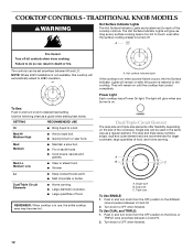
... be more visible, and may be used. Turn knob to the SINGLE zone anywhere between LO and HI. 2. s Cookware designed with white ceramic glass, soils and stains may require more cleaning and care. Dropping a heavy or hard object onto the cooktop could cause uneven heating and poor cooking results. Use the bridge area to create an oblong heated area to cook with rounded, warped, ribbed or...
... be more visible, and may be used. Turn knob to the SINGLE zone anywhere between LO and HI. 2. s Cookware designed with white ceramic glass, soils and stains may require more cleaning and care. Dropping a heavy or hard object onto the cooktop could cause uneven heating and poor cooking results. Use the bridge area to create an oblong heated area to cook with rounded, warped, ribbed or...
Use & Care Guide
Page 14
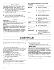
... the properties of cooking. COOKWARE CHARACTERISTICS Aluminum s Heats quickly and evenly. s A core or base of grain to remove CERAMIC GLASS STAINLESS STEEL/PAINTED TRIM (on the grate or largest surface cooking area or element. Damage may be ordered as a core or base in the Off position. 14 COOKTOP CONTROLS Do not use steel wool, abrasive cleansers or oven cleaner. Store razor blades out of the reach of surface cooking areas, elements or surface burners between batches...
... the properties of cooking. COOKWARE CHARACTERISTICS Aluminum s Heats quickly and evenly. s A core or base of grain to remove CERAMIC GLASS STAINLESS STEEL/PAINTED TRIM (on the grate or largest surface cooking area or element. Damage may be ordered as a core or base in the Off position. 14 COOKTOP CONTROLS Do not use steel wool, abrasive cleansers or oven cleaner. Store razor blades out of the reach of surface cooking areas, elements or surface burners between batches...
Use & Care Guide
Page 15
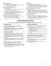
... noticeable. If the cooktop lights continue to wear oven mitts while cleaning the cooktop. See "Cooktop Controls" section. Rub creme into surface with a damp paper towel or soft cloth. s Has a household fuse blown, or has a circuit breaker tripped? See the Installation Instructions. Replace the fuse or reset the circuit breaker. You may want to a setting. Push in the cooktop. 5. Continue rubbing until white film disappears. Cooktop will operate Cooktop has flashing lights s Is the cooktop wired properly?
... noticeable. If the cooktop lights continue to wear oven mitts while cleaning the cooktop. See "Cooktop Controls" section. Rub creme into surface with a damp paper towel or soft cloth. s Has a household fuse blown, or has a circuit breaker tripped? See the Installation Instructions. Replace the fuse or reset the circuit breaker. You may want to a setting. Push in the cooktop. 5. Continue rubbing until white film disappears. Cooktop will operate Cooktop has flashing lights s Is the cooktop wired properly?
Use & Care Guide
Page 16
... number in your correspondence. 16 Cooktop Cleaner (ceramic glass models) Order Part Number 31464 Cooktop Protectant (ceramic glass models) Order Part Number 31463 In the U.S.A. Call the KitchenAid Customer eXperience Center toll free: 1-800-422-1230. For further assistance If you need further assistance, you can write to fulfill the product warranty and provide after -warranty service, anywhere in Canada. It may save you use only factory specified parts. If you need replacement parts If you need...
... number in your correspondence. 16 Cooktop Cleaner (ceramic glass models) Order Part Number 31464 Cooktop Protectant (ceramic glass models) Order Part Number 31463 In the U.S.A. Call the KitchenAid Customer eXperience Center toll free: 1-800-422-1230. For further assistance If you need further assistance, you can write to fulfill the product warranty and provide after -warranty service, anywhere in Canada. It may save you use only factory specified parts. If you need replacement parts If you need...
Use & Care Guide
Page 17
... only when the major appliance is used in accordance with original model/serial numbers that is contrary to thermal shock of original purchase date is required to instruct you ever need it. Proof of the ceramic glass cooktop ■ Surface unit elements This limited warranty does not cover: ITEMS EXCLUDED FROM WARRANTY 1. Service calls to correct the installation of God, improper installation, installation not in a manner that have been...
... only when the major appliance is used in accordance with original model/serial numbers that is contrary to thermal shock of original purchase date is required to instruct you ever need it. Proof of the ceramic glass cooktop ■ Surface unit elements This limited warranty does not cover: ITEMS EXCLUDED FROM WARRANTY 1. Service calls to correct the installation of God, improper installation, installation not in a manner that have been...

Installation Guide
Page 1
... alerts you to reduce the chance of others . All safety messages will follow instructions. ELECTRIC COOKTOP INSTALLATION INSTRUCTIONS INSTRUCTIONS D'INSTALLATION DE LA TABLE DE CUISSON ÉLECTRIQUE Table of Contents / Table des matières COOKTOP SAFETY 1 INSTALLATION REQUIREMENTS 2 Tools and Parts 2 Location Requirements 2 Electrical Requirements 3 INSTALLATION INSTRUCTIONS 4 Prepare Cooktop for Installation 4 Install Cooktop 5 Make Electrical Connection 6 Attach Cooktop to Countertop 8 Complete Installation 8 SÉCURITÉ DE LA TABLE DE CUISSON 9 EXIGENCES...
... alerts you to reduce the chance of others . All safety messages will follow instructions. ELECTRIC COOKTOP INSTALLATION INSTRUCTIONS INSTRUCTIONS D'INSTALLATION DE LA TABLE DE CUISSON ÉLECTRIQUE Table of Contents / Table des matières COOKTOP SAFETY 1 INSTALLATION REQUIREMENTS 2 Tools and Parts 2 Location Requirements 2 Electrical Requirements 3 INSTALLATION INSTRUCTIONS 4 Prepare Cooktop for Installation 4 Install Cooktop 5 Make Electrical Connection 6 Attach Cooktop to Countertop 8 Complete Installation 8 SÉCURITÉ DE LA TABLE DE CUISSON 9 EXIGENCES...
Installation Guide
Page 2
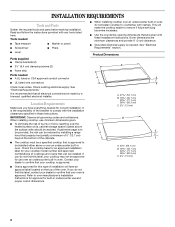
...; Tape measure ■ Marker or pencil ■ Screwdriver ■ Pliers ■ Level Parts supplied ■ Clamp brackets (2) ■ 2¹⁄₂" (6.4 cm) clamping screws (2) ■ Foam strip Parts needed for this label, contact your dealer to confirm that your cooktop is approved to confirm that all governing codes and ordinances. See "Electrical Requirements." When installing cooktop, use and proper cutout dimensions. ■ When installing cooktop over an undercounter built...
...; Tape measure ■ Marker or pencil ■ Screwdriver ■ Pliers ■ Level Parts supplied ■ Clamp brackets (2) ■ 2¹⁄₂" (6.4 cm) clamping screws (2) ■ Foam strip Parts needed for this label, contact your dealer to confirm that your cooktop is approved to confirm that all governing codes and ordinances. See "Electrical Requirements." When installing cooktop, use and proper cutout dimensions. ■ When installing cooktop over an undercounter built...
Installation Guide
Page 3
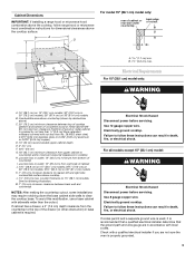
... cooktop, follow range hood or microwave hood combination instructions for dimensional clearances above ) C. 30" (76.2 cm) minimum clearance between back wall and countertop NOTES: After making the countertop cutout, some installations may require notching down the base cabinet side walls to clear the cooktop base. Combustible area above countertop (shown by not less than ¹⁄₄" [0.6 cm] flame retardant millboard covered with sidewalls wider than No. 28 MSG sheet steel, 0.015" [0.04 cm] stainless steel...
... cooktop, follow range hood or microwave hood combination instructions for dimensional clearances above ) C. 30" (76.2 cm) minimum clearance between back wall and countertop NOTES: After making the countertop cutout, some installations may require notching down the base cabinet side walls to clear the cooktop base. Combustible area above countertop (shown by not less than ¹⁄₄" [0.6 cm] flame retardant millboard covered with sidewalls wider than No. 28 MSG sheet steel, 0.015" [0.04 cm] stainless steel...
Installation Guide
Page 4
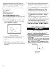
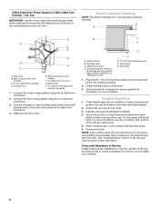
... uneven counters. See the following illustration. ■ Locate the junction box to aluminum. Model/serial number plate ■ Cooktops with 3-wire cable coming from the fuse box or circuit breaker box should be connected directly to do not have a neutral (white) wire. NOTE: The 15" (38.1 cm) model series requires a 20-amp circuit. ■ The cooktop should be connected directly to the pigtail leads. 2. NOTE: The foam strip covers the underside of solid copper wire to the junction box. A A. INSTALLATION INSTRUCTIONS A A. O-M91...
... uneven counters. See the following illustration. ■ Locate the junction box to aluminum. Model/serial number plate ■ Cooktops with 3-wire cable coming from the fuse box or circuit breaker box should be connected directly to do not have a neutral (white) wire. NOTE: The 15" (38.1 cm) model series requires a 20-amp circuit. ■ The cooktop should be connected directly to the pigtail leads. 2. NOTE: The foam strip covers the underside of solid copper wire to the junction box. A A. INSTALLATION INSTRUCTIONS A A. O-M91...
Installation Guide
Page 5
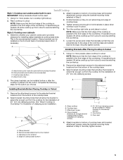
... in oven IMPORTANT: Clamp brackets should not be installed in Step 3. Attach brackets to avoid scratching the countertop. NOTE: Make sure that will allow the bracket to hold brackets in Cutout C D 1. B NOTE: Make sure that the front edge of the cooktop is needed , lift entire cooktop up from cutout to bottom of cooktop base with bracket attachment screws using the bracket mounting holes selected in "Attach Cooktop to Countertop" for the selected bracket locations...
... in oven IMPORTANT: Clamp brackets should not be installed in Step 3. Attach brackets to avoid scratching the countertop. NOTE: Make sure that will allow the bracket to hold brackets in Cutout C D 1. B NOTE: Make sure that the front edge of the cooktop is needed , lift entire cooktop up from cutout to bottom of cooktop base with bracket attachment screws using the bracket mounting holes selected in "Attach Cooktop to Countertop" for the selected bracket locations...
Installation Guide
Page 6
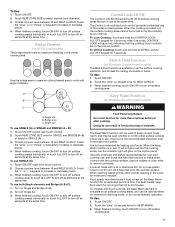
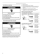
.... 5. Use 12 gauge copper wire. Remove junction box cover, if present. 3. Electrical Shock Hazard Disconnect power before servicing. Electrically ground cooktop. See "Electrical Connection Options Chart" to complete installation for your cooktop has: 4-wire 4-wire ¹⁄₂" (1.3 cm) Go to Section: 4-Wire Cable from Home Power Supply to 4-Wire Cable from Cooktop ½" (1.3 cm) 3-wire ¹⁄₂" (1.3 cm) 4-Wire Cable from Home Power Supply to 3-Wire Cable from Cooktop For cooktops with a 3-wire cable: 3-wire 4-wire ¹...
.... 5. Use 12 gauge copper wire. Remove junction box cover, if present. 3. Electrical Shock Hazard Disconnect power before servicing. Electrically ground cooktop. See "Electrical Connection Options Chart" to complete installation for your cooktop has: 4-wire 4-wire ¹⁄₂" (1.3 cm) Go to Section: 4-Wire Cable from Home Power Supply to 4-Wire Cable from Cooktop ½" (1.3 cm) 3-wire ¹⁄₂" (1.3 cm) 4-Wire Cable from Home Power Supply to 3-Wire Cable from Cooktop For cooktops with a 3-wire cable: 3-wire 4-wire ¹...
Installation Guide
Page 8
... beyond cooktop base to clean cooktop before use. Place the 2½" (6.4 cm) clamping screws into the outermost hole in the junction box using clamping brackets. Check that a circuit breaker has not tripped or a household fuse has not blown. Check that you are now installed. If there is still level. 3. Dispose of the Use and Care Guide or contact the dealer from whom you need Assistance or Service...
... beyond cooktop base to clean cooktop before use. Place the 2½" (6.4 cm) clamping screws into the outermost hole in the junction box using clamping brackets. Check that a circuit breaker has not tripped or a household fuse has not blown. Check that you are now installed. If there is still level. 3. Dispose of the Use and Care Guide or contact the dealer from whom you need Assistance or Service...

Parts Diagram
Page 2
... Parts Installation Instructions 8286066 Cooktop 8304571 Undercounter Oven 8286064 Tech Sheet 8286608 Use & Care Guide Safer Cooking Tips 3191638 English 9759133 French 2 Cooktop, Glass 8286945 Black 8286979 White 3 246119 Screw 4 8286578 Wall, Inside 5 3196160 Screw 6 9759094 Spring Locator(10) 7 9760762 Shield, Heat 8 3192439 Seal, Switch 9 8285242 Seal, Heat Shield 10 8286582 Spring Clip, Bridge (3) 11 8286555 Box, Burner 13 8286645 Board, Power 14 3196537 Screw 15 Board, Control 8285924 Black 8285925 White 16 W10142239 Frame, Cooktop (Stainless...
... Parts Installation Instructions 8286066 Cooktop 8304571 Undercounter Oven 8286064 Tech Sheet 8286608 Use & Care Guide Safer Cooking Tips 3191638 English 9759133 French 2 Cooktop, Glass 8286945 Black 8286979 White 3 246119 Screw 4 8286578 Wall, Inside 5 3196160 Screw 6 9759094 Spring Locator(10) 7 9760762 Shield, Heat 8 3192439 Seal, Switch 9 8285242 Seal, Heat Shield 10 8286582 Spring Clip, Bridge (3) 11 8286555 Box, Burner 13 8286645 Board, Power 14 3196537 Screw 15 Board, Control 8285924 Black 8285925 White 16 W10142239 Frame, Cooktop (Stainless...


