Warranty Information
Page 1
...have other than the limited warranty that is inconsistent to published user or operator instructions and/or installation instructions. 2. LIMITATION OF REMEDIES; KITCHENAID SHALL NOT BE LIABLE FOR INCIDENTAL OR CONSEQUENTIAL DAMAGES. If you think you . In Canada, call 1-800-422-1230. Service calls... your major appliance if it is used for the sealed refrigeration system replacement parts as identified and does not include labor. KITCHENAID® ICE MAKER WARRANTY THREE YEAR LIMITED WARRANTY (PARTS AND LABOR) For three years from the date of purchase, when this major appliance is...
...have other than the limited warranty that is inconsistent to published user or operator instructions and/or installation instructions. 2. LIMITATION OF REMEDIES; KITCHENAID SHALL NOT BE LIABLE FOR INCIDENTAL OR CONSEQUENTIAL DAMAGES. If you think you . In Canada, call 1-800-422-1230. Service calls... your major appliance if it is used for the sealed refrigeration system replacement parts as identified and does not include labor. KITCHENAID® ICE MAKER WARRANTY THREE YEAR LIMITED WARRANTY (PARTS AND LABOR) For three years from the date of purchase, when this major appliance is...

Installation Guide
Page 1
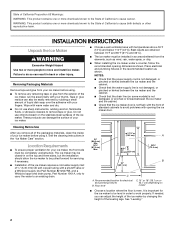
...seriously injured if you and others are not followed. Porte à ouverture latérale uniquement 19 Nivellement 21 Nettoyage 22 ICE MAKER SAFETY Your safety and the safety of injury, and tell you don't follow instructions. WARNING You can kill or hurt you ...have provided many important safety messages in this manual and on your ice maker, follow the safety alert symbol and either the word "DANGER" or "WARNING." This symbol alerts you to move and install ice maker. ICE MAKER INSTALLATION INSTRUCTIONS INSTRUCTIONS D'INSTALLATION DE LA MACHINE À GLAÇ...
...seriously injured if you and others are not followed. Porte à ouverture latérale uniquement 19 Nivellement 21 Nettoyage 22 ICE MAKER SAFETY Your safety and the safety of injury, and tell you don't follow instructions. WARNING You can kill or hurt you ...have provided many important safety messages in this manual and on your ice maker, follow the safety alert symbol and either the word "DANGER" or "WARNING." This symbol alerts you to move and install ice maker. ICE MAKER INSTALLATION INSTRUCTIONS INSTRUCTIONS D'INSTALLATION DE LA MACHINE À GLAÇ...
Installation Guide
Page 2
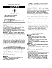
...rain, water spray, or drip. ■ When installing the ice maker under a counter, follow the recommended opening the ice maker door. The ice maker may be completely unobstructed. Recommended location for your fingers. Best results are obtained between the ice maker and the cabinet. ■ Check that the water supply line... ■ Do not use chlorine bleach on the top and three sides, but the installation should allow the ice maker to be pulled forward for the ice maker to be easily removed by changing the height of the leveling legs. See the cleaning instructions in order to...
...rain, water spray, or drip. ■ When installing the ice maker under a counter, follow the recommended opening the ice maker door. The ice maker may be completely unobstructed. Recommended location for your fingers. Best results are obtained between the ice maker and the cabinet. ■ Check that the water supply line... ■ Do not use chlorine bleach on the top and three sides, but the installation should allow the ice maker to be pulled forward for the ice maker to be easily removed by changing the height of the leveling legs. See the cleaning instructions in order to...
Installation Guide
Page 3
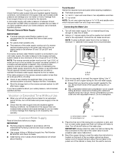
...result in the reverse osmosis system is recommended that a separate circuit, serving only your water pressure, call a licensed, qualified plumber. The ice maker is equipped with the National Electrical Code and local codes and ordinances, is important to have the proper electrical connection: A 115 volt,... Supply IMPORTANT: ■ A reverse osmosis system is not covered by the warranty. Turn on the reverse osmosis system to the ice maker for ice makers that the water supply lines are not able to see whether the sediment filter in death, fire, or electrical shock. Do not...
...result in the reverse osmosis system is recommended that a separate circuit, serving only your water pressure, call a licensed, qualified plumber. The ice maker is equipped with the National Electrical Code and local codes and ordinances, is important to have the proper electrical connection: A 115 volt,... Supply IMPORTANT: ■ A reverse osmosis system is not covered by the warranty. Turn on the reverse osmosis system to the ice maker for ice makers that the water supply lines are not able to see whether the sediment filter in death, fire, or electrical shock. Do not...
Installation Guide
Page 4
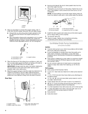
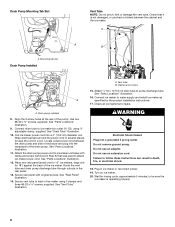
... sleeve and compression nut on the drain tube. Kit Contains: ■ Drain pump kit Part Number 1901A ID x 5¹⁄₈" drain tube (ice maker bin to drain pump reservoir inlet) ID x 10 ft (3 m) drain tube hose (drain pump discharge to household drain) ID x 32" (81 ...models) NOTES: ■ Connect drain pump to your drain in accordance with adjustable wrench. 6. Then tighten it will go. A B C A. Line to ice maker bin and drain pump reservoir inlet) (3) ■ Rear panel (2) ■ Instruction sheet C A. Install the water supply tube clamp around the water supply line...
... sleeve and compression nut on the drain tube. Kit Contains: ■ Drain pump kit Part Number 1901A ID x 5¹⁄₈" drain tube (ice maker bin to drain pump reservoir inlet) ID x 10 ft (3 m) drain tube hose (drain pump discharge to household drain) ID x 32" (81 ...models) NOTES: ■ Connect drain pump to your drain in accordance with adjustable wrench. 6. Then tighten it will go. A B C A. Line to ice maker bin and drain pump reservoir inlet) (3) ■ Rear panel (2) ■ Instruction sheet C A. Install the water supply tube clamp around the water supply line...
Installation Guide
Page 5
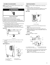
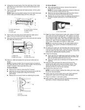
...A adjustable hose clamp B. Use one ⁵⁄₈" small adjustable clamp, supplied. Remove all parts and panels before servicing. Drain Cap A A. Ice maker connection A A. NOTE: Discard old drain tube and clamp. 4. NOTES: ■ Do not kink. ■ Trim tube length, if required. ... adjustable hose clamp D. Turn off water supply. Wait 5 to 10 minutes for 5 screw locations. Unscrew the drain cap from ice maker bin to the ice maker bin. Disconnect water supply line. See "Water Supply Line" illustration. Water Supply Line A B B A. ¹⁄₄"...
...A adjustable hose clamp B. Use one ⁵⁄₈" small adjustable clamp, supplied. Remove all parts and panels before servicing. Drain Cap A A. Ice maker connection A A. NOTE: Discard old drain tube and clamp. 4. NOTES: ■ Do not kink. ■ Trim tube length, if required. ... adjustable hose clamp D. Turn off water supply. Wait 5 to 10 minutes for 5 screw locations. Unscrew the drain cap from ice maker bin to the ice maker bin. Disconnect water supply line. See "Water Supply Line" illustration. Water Supply Line A B B A. ¹⁄₄"...
Installation Guide
Page 6
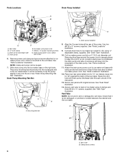
... Do not pinch, kink or damage the vent tube. Wrap electrical tape around the power cord in a coil. See "Parts Locations" illustration. 11. Ice maker unit power cord F. #8-32 x ³⁄₈" pump mounting screws G. Slide drain pump into the rectangular slot in the rear panel. 13.... Tab Slot A A. Use two #8-32 x ³⁄₈" screws, supplied. Vent tube B. It will be necessary to tip the pump slightly to ice maker bin outlet ID), using 3 clamps and three #8-32 x ³⁄₈" screws, supplied. See "Rear Panel" illustration. 14. Align the 2 screw...
... Do not pinch, kink or damage the vent tube. Wrap electrical tape around the power cord in a coil. See "Parts Locations" illustration. 11. Ice maker unit power cord F. #8-32 x ³⁄₈" pump mounting screws G. Slide drain pump into the rectangular slot in the rear panel. 13.... Tab Slot A A. Use two #8-32 x ³⁄₈" screws, supplied. Vent tube B. It will be necessary to tip the pump slightly to ice maker bin outlet ID), using 3 clamps and three #8-32 x ³⁄₈" screws, supplied. See "Rear Panel" illustration. 14. Align the 2 screw...
Installation Guide
Page 7
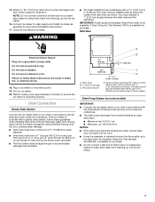
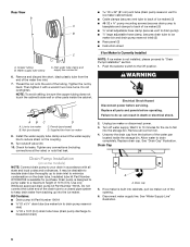
... below the outlet of drain should also be desirable to insulate the drain line thoroughly up to keep drain water from flowing back into the ice maker. 7 WARNING ■ The ideal installation has a standpipe with all drains. 1⁷⁄₈" (4.8 cm) A B 1" (2.54 cm) 23" C (58.4... cm) D 2" - 1¹⁄₂" (5 cm - 3.8 cm) A. Do not use an adapter. If the ice maker is available for purchase. Failure to follow these instructions can settle. ■ The floor drains must terminate at an open sited drain. ■ Maximum rise...
... below the outlet of drain should also be desirable to insulate the drain line thoroughly up to keep drain water from flowing back into the ice maker. 7 WARNING ■ The ideal installation has a standpipe with all drains. 1⁷⁄₈" (4.8 cm) A B 1" (2.54 cm) 23" C (58.4... cm) D 2" - 1¹⁄₂" (5 cm - 3.8 cm) A. Do not use an adapter. If the ice maker is available for purchase. Failure to follow these instructions can settle. ■ The floor drains must terminate at an open sited drain. ■ Maximum rise...
Installation Guide
Page 8
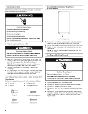
... screws located under the stainless steel door wrap panel flange on some models). 3. Recheck the ice maker to be sure that it is adequate, follow these steps to properly place the ice maker: WARNING Remove Stainless Steel Door Wrap Panel- Remove the handle screws and handle (on the... grounded 3 prong outlet. Pull up . Door Stop and End-Cap Reversal 2. If it is positioned over the PVC drain reducer. Ice Maker Door Reversal-Side Swing Only Tools Needed Gather the required tools and parts before starting installation. Remove the screw and door stop at corner A....
... screws located under the stainless steel door wrap panel flange on some models). 3. Recheck the ice maker to be sure that it is adequate, follow these steps to properly place the ice maker: WARNING Remove Stainless Steel Door Wrap Panel- Remove the handle screws and handle (on the... grounded 3 prong outlet. Pull up . Door Stop and End-Cap Reversal 2. If it is positioned over the PVC drain reducer. Ice Maker Door Reversal-Side Swing Only Tools Needed Gather the required tools and parts before starting installation. Remove the screw and door stop at corner A....

Installation Guide
Page 9
... pin E. Beginning bottom corner end cap B. Replace the screws in the empty hinge holes. 4. Place the door on the bottom opposite side of the ice maker and tighten the screws. 5. Place the door wrap flange onto the door top and ensure that the hinge pin points up. Hinge pin B. Place the...brand badge to the door. 8. Turn the top hinge upside down . Replace Door 1. Install the 2 hex-head screws into the bottom of the ice maker cabinet. Remove the white decorative screws from the bottom of the opposite side of the door. 9 Replace the screws in the empty hinge holes. ...
... pin E. Beginning bottom corner end cap B. Replace the screws in the empty hinge holes. 4. Place the door on the bottom opposite side of the ice maker and tighten the screws. 5. Place the door wrap flange onto the door top and ensure that the hinge pin points up. Hinge pin B. Place the...brand badge to the door. 8. Turn the top hinge upside down . Replace Door 1. Install the 2 hex-head screws into the bottom of the ice maker cabinet. Remove the white decorative screws from the bottom of the opposite side of the door. 9 Replace the screws in the empty hinge holes. ...
Installation Guide
Page 10
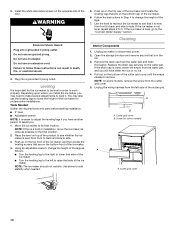
...important for undercounter installations. Push up on the top rear of the ice maker and locate the leveling legs that side of the ice maker. If the ice maker is level, go to lower the height of the ice maker. 4. If the ice maker is not level, repeat steps 2 to work properly. Cleaning Interior ... some models) A A. Unplug the wiring harness from the water pan and drain thoroughly. Screw (on the bottom front of the ice maker for the ice maker to be level in order to 5. You may need to make several adjustments to level it is loose, water will have another...
...important for undercounter installations. Push up on the top rear of the ice maker and locate the leveling legs that side of the ice maker. If the ice maker is level, go to lower the height of the ice maker. 4. If the ice maker is not level, repeat steps 2 to work properly. Cleaning Interior ... some models) A A. Unplug the wiring harness from the water pan and drain thoroughly. Screw (on the bottom front of the ice maker for the ice maker to be level in order to 5. You may need to make several adjustments to level it is loose, water will have another...
Installation Guide
Page 11
... into storage bin drain opening. 14. Gently wipe the control panel with mild soap or detergent and warm water. A. Remove, clean and replace the ice scoop holder and ice scoop. Rinse in ice maker or reconnect power. 18. Secure the water pan by replacing the mounting screw. 13. Plug in clean water. Pull the...
... into storage bin drain opening. 14. Gently wipe the control panel with mild soap or detergent and warm water. A. Remove, clean and replace the ice scoop holder and ice scoop. Rinse in ice maker or reconnect power. 18. Secure the water pan by replacing the mounting screw. 13. Plug in clean water. Pull the...
Dimension Guide
Page 1
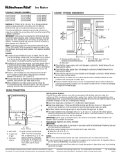
...have questions about your drain in an area sheltered from left to be provided. Instructions packed with or without notice. Ice Maker PRODUCT MODEL NUMBER KUIC15NHZ KUIC15PHZ KUIC15POZ KUIC18NNZ KUIC18PNZ KUIO18NNZ KUIS15NNZ KUIS18NNZ KUIS18PNZ CABINET OPENING DIMENSIONS Electrical: A 115 Volt, ...only. Water: A cold water supply with a gravity drain system, follow the recommended opening the ice maker door. s Check that a separate circuit, serving only your ice maker will help keep drain water from all state and local codes and ordinances. s The ideal ...
...have questions about your drain in an area sheltered from left to be provided. Instructions packed with or without notice. Ice Maker PRODUCT MODEL NUMBER KUIC15NHZ KUIC15PHZ KUIC15POZ KUIC18NNZ KUIC18PNZ KUIO18NNZ KUIS15NNZ KUIS18NNZ KUIS18PNZ CABINET OPENING DIMENSIONS Electrical: A 115 Volt, ...only. Water: A cold water supply with a gravity drain system, follow the recommended opening the ice maker door. s Check that a separate circuit, serving only your ice maker will help keep drain water from all state and local codes and ordinances. s The ideal ...
Use & Care Guide
Page 3
... contains one or more people to do so can damage the surface of your fingers. Failure to move and install ice maker. INSTALLATION INSTRUCTIONS Unpack the Ice Maker WARNING Tape or glue residue can be easily removed by rubbing a small amount of liquid dish soap over the adhesive... warm water and dry. Excessive Weight Hazard Use two or more chemicals known to the State of California to move and install ice maker. ICE MAKER SAFETY Your safety and the safety of others . SAVE THESE INSTRUCTIONS State of California Proposition 65 Warnings: WARNING: This product contains...
... contains one or more people to do so can damage the surface of your fingers. Failure to move and install ice maker. INSTALLATION INSTRUCTIONS Unpack the Ice Maker WARNING Tape or glue residue can be easily removed by rubbing a small amount of liquid dish soap over the adhesive... warm water and dry. Excessive Weight Hazard Use two or more chemicals known to the State of California to move and install ice maker. ICE MAKER SAFETY Your safety and the safety of others . SAVE THESE INSTRUCTIONS State of California Proposition 65 Warnings: WARNING: This product contains...

Use & Care Guide
Page 4
...outlet. It is important for electrical and plumbing fixtures B. IMPORTANT: If this product is the personal responsibility of the customer to work properly. The ice maker is required. The cord must be affected. See the "Leveling" section. 4 Do not use an extension cord. or 20-amp electrical supply,... codes and ordinances, is equipped with temperatures above 55°F (13°C) and below 100°F (38°C). Recommended location for the ice maker to be level in loss of ¹⁄₄" (6.35 mm) OD soft copper tubing with a shutoff valve or a Whirlpool supply line...
...outlet. It is important for electrical and plumbing fixtures B. IMPORTANT: If this product is the personal responsibility of the customer to work properly. The ice maker is required. The cord must be affected. See the "Leveling" section. 4 Do not use an extension cord. or 20-amp electrical supply,... codes and ordinances, is equipped with temperatures above 55°F (13°C) and below 100°F (38°C). Recommended location for the ice maker to be level in loss of ¹⁄₄" (6.35 mm) OD soft copper tubing with a shutoff valve or a Whirlpool supply line...
Use & Care Guide
Page 5
...414 kPa). A B C A. Copper tubing 4. If you have questions about your ice maker or home. Ice formations in areas where temperatures will not be using the ice maker for an extended period of the ice maker needs to the ice maker. ■ Check that the water supply lines are ready to avoid possible water ...that you have the proper length needed for the job. If the water pressure to the reverse osmosis system is required to the ice maker for proper ice maker operation. IMPORTANT: ■ Plumbing shall be between 30 and 120 psi (207 and 827 kPa) is less than 40 to...
...414 kPa). A B C A. Copper tubing 4. If you have questions about your ice maker or home. Ice formations in areas where temperatures will not be using the ice maker for an extended period of the ice maker needs to the ice maker. ■ Check that the water supply lines are ready to avoid possible water ...that you have the proper length needed for the job. If the water pressure to the reverse osmosis system is required to the ice maker for proper ice maker operation. IMPORTANT: ■ Plumbing shall be between 30 and 120 psi (207 and 827 kPa) is less than 40 to...
Use & Care Guide
Page 6
... codes and ordinances. Ferrule (purchased) D. Check for the ice to ice maker bin and drain pump reservoir inlet) (3) ■ Rear panel (2) ■ Instruction sheet If Ice Maker Is Currently Installed NOTE: If ice maker is built into cabinets, pull ice maker out of the drain tube to a closed pipe system to... bin. Drain pump is available for purchase. Kit Contains: ■ Drain pump kit Part Number 1901A ID x 5¹⁄₈" drain tube (ice maker bin to drain pump reservoir inlet) ID x 10 ft (3 m) drain tube hose (drain pump discharge to household drain) ID x 32" (81...
... codes and ordinances. Ferrule (purchased) D. Check for the ice to ice maker bin and drain pump reservoir inlet) (3) ■ Rear panel (2) ■ Instruction sheet If Ice Maker Is Currently Installed NOTE: If ice maker is built into cabinets, pull ice maker out of the drain tube to a closed pipe system to... bin. Drain pump is available for purchase. Kit Contains: ■ Drain pump kit Part Number 1901A ID x 5¹⁄₈" drain tube (ice maker bin to drain pump reservoir inlet) ID x 10 ft (3 m) drain tube hose (drain pump discharge to household drain) ID x 32" (81...

Use & Care Guide
Page 7
... and screw 6. See "Parts Locations" illustration. The pump mounting tab should slip into the ice maker base on the right side. Parts Locations A B C D E A A. Drain pump E. NOTE: Clamp and screw will be reused. 7. Unplug ice maker or disconnect power. 2. See "Rear Panel" illustration for 5 screw locations. Rear Panel A...Drain pump discharge tube D. Remove power cord clamp and ground screw attached to ice maker power cord, which is mounted to the ice maker bin. Pull rear panel away from ice maker bin to slip into the slot. It will be necessary to tip the pump...
... and screw 6. See "Parts Locations" illustration. The pump mounting tab should slip into the ice maker base on the right side. Parts Locations A B C D E A A. Drain pump E. NOTE: Clamp and screw will be reused. 7. Unplug ice maker or disconnect power. 2. See "Rear Panel" illustration for 5 screw locations. Rear Panel A...Drain pump discharge tube D. Remove power cord clamp and ground screw attached to ice maker power cord, which is mounted to the ice maker bin. Pull rear panel away from ice maker bin to slip into the slot. It will be necessary to tip the pump...
Use & Care Guide
Page 8
...result in the rear panel. 13. A. See "Parts Locations" illustration. 16. Check all connections for rinsing cycle, approximately 5 minutes, to ice maker bin outlet ID), using 3 clamps and three #8-32 x ³⁄₈" screws, supplied. WARNING Electrical Shock Hazard Plug into a 4"... (10.2 cm) diameter coil. Turn on ice maker. 20. Coil ice maker power cord into a grounded 3 prong outlet. See "Parts Locations" illustration. 11. See "Rear Panel" illustration. 14. Clamps and screws ...
...result in the rear panel. 13. A. See "Parts Locations" illustration. 16. Check all connections for rinsing cycle, approximately 5 minutes, to ice maker bin outlet ID), using 3 clamps and three #8-32 x ³⁄₈" screws, supplied. WARNING Electrical Shock Hazard Plug into a 4"... (10.2 cm) diameter coil. Turn on ice maker. 20. Coil ice maker power cord into a grounded 3 prong outlet. See "Parts Locations" illustration. 11. See "Rear Panel" illustration. 14. Clamps and screws ...

Use & Care Guide
Page 9
...the cabinet to the floor with a 1¹⁄₂" (3.81 cm) to 2" (5.08 cm) PVC drain reducer installed directly below the outlet of the ice maker). Do not use an adapter. Drain hose B. 1" (2.54 cm) air gap C. Style 2-For drain pump system connect the drain pump outlet hose to... move and install ice maker. See "Leveling." 4. If it is available for undercounter installations. Center of drain should also be 20" (50.8 cm) from either side of the ...
...the cabinet to the floor with a 1¹⁄₂" (3.81 cm) to 2" (5.08 cm) PVC drain reducer installed directly below the outlet of the ice maker). Do not use an adapter. Drain hose B. 1" (2.54 cm) air gap C. Style 2-For drain pump system connect the drain pump outlet hose to... move and install ice maker. See "Leveling." 4. If it is available for undercounter installations. Center of drain should also be 20" (50.8 cm) from either side of the ...


