
Dimension Guide
Page 1
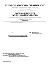
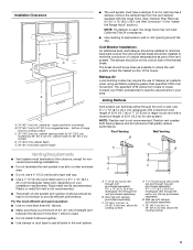
..., 15-amp, fused electrical circuit is not recommended. q Wire sizes and connections must conform to change without notice. VENTING METHODS Vent system can terminate either through the wall or out the top (purchased separately) B. above the cooking surface To calculate the length of the range hood. upper cabinet to countertop B. 18" (45.7 cm) to cooking surface C. 30" (76.2 cm) min. The model/serial plate is located behind the filter on the model/serial rating plate. clearance...
..., 15-amp, fused electrical circuit is not recommended. q Wire sizes and connections must conform to change without notice. VENTING METHODS Vent system can terminate either through the wall or out the top (purchased separately) B. above the cooking surface To calculate the length of the range hood. upper cabinet to countertop B. 18" (45.7 cm) to cooking surface C. 30" (76.2 cm) min. The model/serial plate is located behind the filter on the model/serial rating plate. clearance...
Use & Care Guide
Page 1
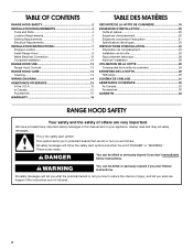
...) RANGE HOOD Installation Instructions and Use & Care Guide For questions about features, operation/performance, parts, accessories or service, call: 1-800-253-1301 or visit our website at www.whirlpool.com In Canada, call 1-800-807-6777 or visit our website at www.whirlpool.ca HOTTE D'ASPIRATION DE 30" (76,2 CM) ET 36" (91,4 CM) Instructions d'installation et Guide d'utilisation et d'entretien Au Canada, pour assistance, installation ou service, composer...
...) RANGE HOOD Installation Instructions and Use & Care Guide For questions about features, operation/performance, parts, accessories or service, call: 1-800-253-1301 or visit our website at www.whirlpool.com In Canada, call 1-800-807-6777 or visit our website at www.whirlpool.ca HOTTE D'ASPIRATION DE 30" (76,2 CM) ET 36" (91,4 CM) Instructions d'installation et Guide d'utilisation et d'entretien Au Canada, pour assistance, installation ou service, composer...
Use & Care Guide
Page 2
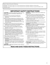
... is the safety alert symbol. Always read and obey all safety messages. TABLE OF CONTENTS RANGE HOOD SAFETY 2 INSTALLATION REQUIREMENTS 4 Tools and Parts 4 Location Requirements 4 Venting Requirements 5 Electrical Requirements 7 INSTALLATION INSTRUCTIONS 7 Prepare Location 7 Install Range Hood 9 Make Electrical Connection 12 Complete Installation 12 RANGE HOOD USE 13 Range Hood Controls 13 RANGE HOOD CARE 13 Cleaning 13 WIRING DIAGRAM 14 ASSISTANCE OR SERVICE 15 In the U.S.A 15 In Canada 15 Accessories 15 WARRANTY 16 TABLE DES MATIÈRES SÉCURITÉ DE LA...
... is the safety alert symbol. Always read and obey all safety messages. TABLE OF CONTENTS RANGE HOOD SAFETY 2 INSTALLATION REQUIREMENTS 4 Tools and Parts 4 Location Requirements 4 Venting Requirements 5 Electrical Requirements 7 INSTALLATION INSTRUCTIONS 7 Prepare Location 7 Install Range Hood 9 Make Electrical Connection 12 Complete Installation 12 RANGE HOOD USE 13 Range Hood Controls 13 RANGE HOOD CARE 13 Cleaning 13 WIRING DIAGRAM 14 ASSISTANCE OR SERVICE 15 In the U.S.A 15 In Canada 15 Accessories 15 WARRANTY 16 TABLE DES MATIÈRES SÉCURITÉ DE LA...
Use & Care Guide
Page 3
... not use only. Grease should not be sure to duct air outside - you may ignite. IMPORTANT SAFETY INSTRUCTIONS WARNING: TO REDUCE THE RISK OF FIRE, ELECTRIC SHOCK, OR INJURY TO PERSONS, OBSERVE THE FOLLOWING: ■ Use this fan with a close fitting lid, cookie sheet, or metal tray, then turn hood ON when cooking at high settings. CAUTION: To reduce risk of fire and to properly exhaust air...
... not use only. Grease should not be sure to duct air outside - you may ignite. IMPORTANT SAFETY INSTRUCTIONS WARNING: TO REDUCE THE RISK OF FIRE, ELECTRIC SHOCK, OR INJURY TO PERSONS, OBSERVE THE FOLLOWING: ■ Use this fan with a close fitting lid, cookie sheet, or metal tray, then turn hood ON when cooking at high settings. CAUTION: To reduce risk of fire and to properly exhaust air...
Use & Care Guide
Page 4
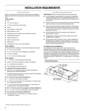
...) round vent mounting plate. The model/serial rating plate is required. Tools needed ■ 1 - 75W max, 120V incandescent light bulb ■ Wall or roof cap with local codes. Consult the cooktop/range manufacturer installation instructions before starting installation. Length and thickness determined by recess dimensions. ■ Four flat head wood screws or machine screws with any cutouts. ■ Grounded electrical outlet is located inside the range hood on ordering, see the "Accessories" section. See "Electrical Requirements" section. ■ All openings in ceiling and wall...
...) round vent mounting plate. The model/serial rating plate is required. Tools needed ■ 1 - 75W max, 120V incandescent light bulb ■ Wall or roof cap with local codes. Consult the cooktop/range manufacturer installation instructions before starting installation. Length and thickness determined by recess dimensions. ■ Four flat head wood screws or machine screws with any cutouts. ■ Grounded electrical outlet is located inside the range hood on ordering, see the "Accessories" section. See "Electrical Requirements" section. ■ All openings in ceiling and wall...
Use & Care Guide
Page 5
cabinet opening around the cap. cabinet width for 36" (91.4 cm) models D. 13" (33.0 cm) cabinet depth E. 36" (91.4 cm) base cabinet height Venting Requirements ■ Vent system must have a damper. Rigid metal vent is used . ■ Do not install 2 elbows together. ■ Use clamps or duct tape to seal exterior wall or roof opening width for vent system. The specified CFM varies from the vent damper supplied with a maximum length of elbows should be installed to provide...
cabinet opening around the cap. cabinet width for 36" (91.4 cm) models D. 13" (33.0 cm) cabinet depth E. 36" (91.4 cm) base cabinet height Venting Requirements ■ Vent system must have a damper. Rigid metal vent is used . ■ Do not install 2 elbows together. ■ Use clamps or duct tape to seal exterior wall or roof opening width for vent system. The specified CFM varies from the vent damper supplied with a maximum length of elbows should be installed to provide...
Use & Care Guide
Page 6
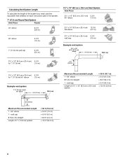
wall cap Length of the system you need, add the equivalent feet (meters) for each vent piece used in the system. 7" (17.8 cm) Round Vent System Vent Piece Round 45° elbow 2.5 ft (0.8 m) 90° elbow 5.0 ft (1.5 m) 7" (17.8 cm) wall cap 0.0 ft (0.0 m) 3¹⁄₄" x 10" (8.3 cm x 25.4 cm) Vent System Vent Piece 3¹⁄₄" x 10" (8.3 cm x 25.4 cm) 5.0 ft 90° elbow (1.5 m) 3¹⁄₄" x 10...
wall cap Length of the system you need, add the equivalent feet (meters) for each vent piece used in the system. 7" (17.8 cm) Round Vent System Vent Piece Round 45° elbow 2.5 ft (0.8 m) 90° elbow 5.0 ft (1.5 m) 7" (17.8 cm) wall cap 0.0 ft (0.0 m) 3¹⁄₄" x 10" (8.3 cm x 25.4 cm) Vent System Vent Piece 3¹⁄₄" x 10" (8.3 cm x 25.4 cm) 5.0 ft 90° elbow (1.5 m) 3¹⁄₄" x 10...
Use & Care Guide
Page 7
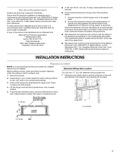
... model/serial plate is required. ■ If the house has aluminum wiring, follow the procedure below: 1. INSTALLATION INSTRUCTIONS Prepare Location NOTE: It is recommended that the ground path is adequate and in the area the vent opening will be installed before hood is proper clearance within the ceiling or wall for assembling the range hood. Determine and clearly mark a vertical centerline on each side. Install screws to use: roof, wall or...
... model/serial plate is required. ■ If the house has aluminum wiring, follow the procedure below: 1. INSTALLATION INSTRUCTIONS Prepare Location NOTE: It is recommended that the ground path is adequate and in the area the vent opening will be installed before hood is proper clearance within the ceiling or wall for assembling the range hood. Determine and clearly mark a vertical centerline on each side. Install screws to use: roof, wall or...
Use & Care Guide
Page 8
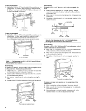
...wall, not cabinet frame 8 Mark lines 5¼" (13.3 cm) to Round Vent Transition Roof Venting To make a circular vent opening for the vent. Use saber or keyhole saw to cut a rectangular opening on the centerline of the underside of cabinet bottom: 1. Cabinet front Centerline Centerline A. 8³⁄₈" (21.3 cm) To wire through top: 1. Cut Openings for vent. 4. Use...a diameter that is 2" (5.1 cm) from wall, not cabinet frame Wall Venting To make a 4¹⁄₄" x 10½" (10.8 cm x 26.7 cm) rectangular cutout on this point. ⁷⁄₈" ...
...wall, not cabinet frame 8 Mark lines 5¼" (13.3 cm) to Round Vent Transition Roof Venting To make a circular vent opening for the vent. Use saber or keyhole saw to cut a rectangular opening on the centerline of the underside of cabinet bottom: 1. Cabinet front Centerline Centerline A. 8³⁄₈" (21.3 cm) To wire through top: 1. Cut Openings for vent. 4. Use...a diameter that is 2" (5.1 cm) from wall, not cabinet frame Wall Venting To make a 4¹⁄₄" x 10½" (10.8 cm x 26.7 cm) rectangular cutout on this point. ⁷⁄₈" ...
Use & Care Guide
Page 9
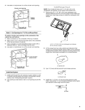
... your range hood. Use a compass or a circle template to slide range hood into place. ¹⁄₄" (6.4 mm) 9 Drill pilot hole. 4. See "Venting Requirements" section. 2. Leave about ¹⁄₄" (6.4 mm) space between screw heads and cabinet to draw a circle with 3.5 x 9.5 mm screws on the range hood. Mark on the underside of cabinet the location of the range hood. 1. Install the 4 - 4.5 mm x 13 mm mounting screws in upper cabinet or wall. cabinet cutouts...
... your range hood. Use a compass or a circle template to slide range hood into place. ¹⁄₄" (6.4 mm) 9 Drill pilot hole. 4. See "Venting Requirements" section. 2. Leave about ¹⁄₄" (6.4 mm) space between screw heads and cabinet to draw a circle with 3.5 x 9.5 mm screws on the range hood. Mark on the underside of cabinet the location of the range hood. 1. Install the 4 - 4.5 mm x 13 mm mounting screws in upper cabinet or wall. cabinet cutouts...
Use & Care Guide
Page 10
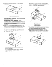
...; If a vent damper is required. Remove top rectangular and round vent knockouts. For information on ordering, see "Accessories" section) B. 3.5 x 9.5 mm screws C. 7" (17.8 cm) round vent mounting plate. Recirculation cover plate B. Remove the two screws from the recirculation cover plate and remove. Round vent knockout E. Remove vent knockouts depending on either side of the recirculation cover plate is installed with a wall cap with each other. Top rectangular vent knockout C. For roof installations, remove the top rectangular vent knockout. Non-vent (recirculating...
...; If a vent damper is required. Remove top rectangular and round vent knockouts. For information on ordering, see "Accessories" section) B. 3.5 x 9.5 mm screws C. 7" (17.8 cm) round vent mounting plate. Recirculation cover plate B. Remove the two screws from the recirculation cover plate and remove. Round vent knockout E. Remove vent knockouts depending on either side of the recirculation cover plate is installed with a wall cap with each other. Top rectangular vent knockout C. For roof installations, remove the top rectangular vent knockout. Non-vent (recirculating...
Use & Care Guide
Page 11
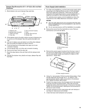
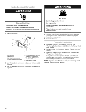
... wire guide and plastic end cap to the National Electric Code or CSA standards and local codes and ordinances. Remove the foam from the fused disconnect (or circuit breaker) box to hood. Power Supply Cable Installation 1. For direct wire installations, run the home power supply cable according to remove. 4. Remove the screw from the top or rear of the vent hood (depending on the incoming location of the keyhole slots are flush with range hood cord connection kits that back draft dampers work...
... wire guide and plastic end cap to the National Electric Code or CSA standards and local codes and ordinances. Remove the foam from the fused disconnect (or circuit breaker) box to hood. Power Supply Cable Installation 1. For direct wire installations, run the home power supply cable according to remove. 4. Remove the screw from the top or rear of the vent hood (depending on the incoming location of the keyhole slots are flush with range hood cord connection kits that back draft dampers work...
Use & Care Guide
Page 12
... power before operating. UL listed wire connector D. Use UL listed wire connectors and connect black wires (B) together. Complete Installation 1. Black wires C. UL listed or CSA approved ½" strain relief G. Use UL listed wire connectors and connect white wires (A) together. 3. Failure to do so can result in death or electrical shock. 1. Install terminal box cover. 6. Replace grease filter if removed. See "Range Hood Use" section. Replace all parts and panels before servicing. Green (or bare) ground wire E. See "Replacing the Incandescent Light Bulb...
... power before operating. UL listed wire connector D. Use UL listed wire connectors and connect black wires (B) together. Complete Installation 1. Black wires C. UL listed or CSA approved ½" strain relief G. Use UL listed wire connectors and connect white wires (A) together. 3. Failure to do so can result in death or electrical shock. 1. Install terminal box cover. 6. Replace grease filter if removed. See "Range Hood Use" section. Replace all parts and panels before servicing. Green (or bare) ground wire E. See "Replacing the Incandescent Light Bulb...
Use & Care Guide
Page 13
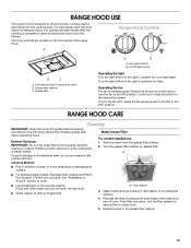
... for High. Replace grease filter before cooking and allow it to operate several minutes after the cooking is designed to remove smoke, cooking vapors and odors from the cooktop area. Exterior Surfaces: IMPORTANT: Do not use cleaners that contain chlorine. For best results, start the hood before operating hood. Grease filter A B A. Turn the light switch to the right 2 positions for Low (night light). RANGE HOOD CARE Cleaning IMPORTANT: Clean the hood and grease filters frequently according to the stainless steel, do not use soap...
... for High. Replace grease filter before cooking and allow it to operate several minutes after the cooking is designed to remove smoke, cooking vapors and odors from the cooktop area. Exterior Surfaces: IMPORTANT: Do not use cleaners that contain chlorine. For best results, start the hood before operating hood. Grease filter A B A. Turn the light switch to the right 2 positions for Low (night light). RANGE HOOD CARE Cleaning IMPORTANT: Clean the hood and grease filters frequently according to the stainless steel, do not use soap...
Use & Care Guide
Page 14
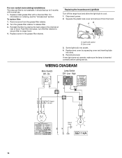
... the range hood and allow the light bulb to release filter. 3. Disconnect power. 2. On BK Lamp Switch Off - For non-vented (recirculating) installations: The charcoal filter is inserted correctly before calling service. Turn the grease filter retainer to cool. 1. AB A. Low - Push filter into socket. 4. Squeeze the plastic lens cover and remove it from the grease filter retainer. 2. Screw light bulb into place, turn the filter retainer to secure filter to 6 months with a charcoal filter. WIRING DIAGRAM R Motor Switch Off - High 1 2 Lamp Switch Operation...
... the range hood and allow the light bulb to release filter. 3. Disconnect power. 2. On BK Lamp Switch Off - For non-vented (recirculating) installations: The charcoal filter is inserted correctly before calling service. Turn the grease filter retainer to cool. 1. AB A. Low - Push filter into socket. 4. Squeeze the plastic lens cover and remove it from the grease filter retainer. 2. Screw light bulb into place, turn the filter retainer to secure filter to 6 months with a charcoal filter. WIRING DIAGRAM R Motor Switch Off - High 1 2 Lamp Switch Operation...
Use & Care Guide
Page 15
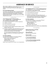
... a daytime phone number in your telephone directory Yellow Pages. Whirlpool Canada LP designated service technicians are trained to fulfill the product warranty and provide afterwarranty service, anywhere in your area, call us to better respond to your correspondence. Accessories Stainless Steel Cleaner and Polish Order Part Number 31462A Charcoal Filter Kit Order Part Number W10355450 Power Cord Kit Order Part Number W10355452 7" (17.8 cm) Round Damper Order Part Number W10355451 7" (17.8 cm) Round Vent Mounting Plate Order Part Number W10388168 15
... a daytime phone number in your telephone directory Yellow Pages. Whirlpool Canada LP designated service technicians are trained to fulfill the product warranty and provide afterwarranty service, anywhere in your area, call us to better respond to your correspondence. Accessories Stainless Steel Cleaner and Polish Order Part Number 31462A Charcoal Filter Kit Order Part Number W10355450 Power Cord Kit Order Part Number W10355452 7" (17.8 cm) Round Damper Order Part Number W10355451 7" (17.8 cm) Round Vent Mounting Plate Order Part Number W10388168 15

Use & Care Guide
Page 16
... authorized Whirlpool Service Providers. Please take a few minutes to review the Troubleshooting or Problem Solver section of repair or replacement under this limitation may not apply to chemicals. 10. This limited warranty is valid only in the United States or Canada and applies only when the major appliance is installed, operated and maintained according to instructions attached to Whirlpool within 30 days. 9. Repairs to parts or...
... authorized Whirlpool Service Providers. Please take a few minutes to review the Troubleshooting or Problem Solver section of repair or replacement under this limitation may not apply to chemicals. 10. This limited warranty is valid only in the United States or Canada and applies only when the major appliance is installed, operated and maintained according to instructions attached to Whirlpool within 30 days. 9. Repairs to parts or...

Use & Care Guide
Page 17
Keep this information on the model and serial number label located on the product. Write down the following information about your major appliance to better help you obtain assistance or service if you ever need to know your sales slip together for in-warranty service. You can find this book and your complete model number and serial number. Dealer name Address Phone number Model number Serial number Purchase date 17 You must provide proof of purchase or installation date for future reference. You will need it.
Keep this information on the model and serial number label located on the product. Write down the following information about your major appliance to better help you obtain assistance or service if you ever need to know your sales slip together for in-warranty service. You can find this book and your complete model number and serial number. Dealer name Address Phone number Model number Serial number Purchase date 17 You must provide proof of purchase or installation date for future reference. You will need it.
Warranty Information
Page 1
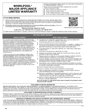
... THIS LIMITED WARRANTY SHALL BE PRODUCT REPAIR AS PROVIDED HEREIN. house wiring, fuses or water inlet hoses). 4. Consumable parts (i.e. This warranty gives you specific legal rights, and you also may not apply to use with electrical or plumbing codes or correction of purchase, when this limited warranty. 1. WHIRLPOOL SHALL NOT BE LIABLE FOR INCIDENTAL OR CONSEQUENTIAL DAMAGES. light bulbs, batteries, air or water filters, preservation solutions, etc.). 5. Removal...
... THIS LIMITED WARRANTY SHALL BE PRODUCT REPAIR AS PROVIDED HEREIN. house wiring, fuses or water inlet hoses). 4. Consumable parts (i.e. This warranty gives you specific legal rights, and you also may not apply to use with electrical or plumbing codes or correction of purchase, when this limited warranty. 1. WHIRLPOOL SHALL NOT BE LIABLE FOR INCIDENTAL OR CONSEQUENTIAL DAMAGES. light bulbs, batteries, air or water filters, preservation solutions, etc.). 5. Removal...

Warranty Information
Page 2
You can find this book and your complete model number and serial number. You will need it. Dealer name Address Phone number Model number Serial number Purchase date 17 Keep this information on the model and serial number label located on the product. Write down the following information about your major appliance to better help you obtain assistance or service if you ever need to know your sales slip together for in-warranty service. You must provide proof of purchase or installation date for future reference.
You can find this book and your complete model number and serial number. You will need it. Dealer name Address Phone number Model number Serial number Purchase date 17 Keep this information on the model and serial number label located on the product. Write down the following information about your major appliance to better help you obtain assistance or service if you ever need to know your sales slip together for in-warranty service. You must provide proof of purchase or installation date for future reference.


