
Dimension Guide
Page 1
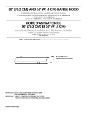
...) B. bottom of copper wire using special connectors and/or tools designed and UL listed for vent system. Specifications subject to the added section of range hood to 7" (17.8 cm) 90° elbow (1.5 m) Example vent system 7" (17.8 cm) round 90˚ elbow 6 ft (1.8 m) Wall cap 2 ft (0.6 m) Maximum... codes and industry accepted wiring practices. to the pigtail leads. 2. clearance - Ref. 30" (76.2 cm) and 36" (91.4 cm) Range Hood PRODUCT MODEL NUMBERS UXT4230AY UXT4236AY Electrical: q A 120 volt, 60 Hz., AC only, 15-amp, fused electrical circuit is located behind the filter on ...
...) B. bottom of copper wire using special connectors and/or tools designed and UL listed for vent system. Specifications subject to the added section of range hood to 7" (17.8 cm) 90° elbow (1.5 m) Example vent system 7" (17.8 cm) round 90˚ elbow 6 ft (1.8 m) Wall cap 2 ft (0.6 m) Maximum... codes and industry accepted wiring practices. to the pigtail leads. 2. clearance - Ref. 30" (76.2 cm) and 36" (91.4 cm) Range Hood PRODUCT MODEL NUMBERS UXT4230AY UXT4236AY Electrical: q A 120 volt, 60 Hz., AC only, 15-amp, fused electrical circuit is located behind the filter on ...
Use & Care Guide
Page 1
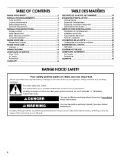
IMPORTANT : LIRE ET CONSERVER CES INSTRUCTIONS. LI3Z4C/W10400322D FOR RESIDENTIAL USE ONLY. POUR UTILISATION RÉSIDENTIELLE UNIQUEMENT. 30" (76.2 CM) AND 36" (91.4 CM) RANGE HOOD Installation Instructions and Use & Care Guide For questions about features, operation/performance, parts, accessories or service, call: 1-800-253-1301 or visit our website at ...
IMPORTANT : LIRE ET CONSERVER CES INSTRUCTIONS. LI3Z4C/W10400322D FOR RESIDENTIAL USE ONLY. POUR UTILISATION RÉSIDENTIELLE UNIQUEMENT. 30" (76.2 CM) AND 36" (91.4 CM) RANGE HOOD Installation Instructions and Use & Care Guide For questions about features, operation/performance, parts, accessories or service, call: 1-800-253-1301 or visit our website at ...
Use & Care Guide
Page 2
...4 Location Requirements 4 Venting Requirements 5 Electrical Requirements 7 INSTALLATION INSTRUCTIONS 7 Prepare Location 7 Install Range Hood 9 Make Electrical Connection 12 Complete Installation 12 RANGE HOOD USE 13 Range Hood Controls 13 RANGE HOOD CARE 13 Cleaning 13 WIRING DIAGRAM 14 ASSISTANCE OR SERVICE 15 In the U.S.A 15 In Canada 15...Nettoyage 29 SCHÉMA DE CÂBLAGE 31 ASSISTANCE OU SERVICE 32 Au Canada 32 Accessoires 32 GARANTIE 33 RANGE HOOD SAFETY Your safety and the safety of injury, and tell you what the potential hazard is the safety alert symbol....
...4 Location Requirements 4 Venting Requirements 5 Electrical Requirements 7 INSTALLATION INSTRUCTIONS 7 Prepare Location 7 Install Range Hood 9 Make Electrical Connection 12 Complete Installation 12 RANGE HOOD USE 13 Range Hood Controls 13 RANGE HOOD CARE 13 Cleaning 13 WIRING DIAGRAM 14 ASSISTANCE OR SERVICE 15 In the U.S.A 15 In Canada 15...Nettoyage 29 SCHÉMA DE CÂBLAGE 31 ASSISTANCE OU SERVICE 32 Au Canada 32 Accessoires 32 GARANTIE 33 RANGE HOOD SAFETY Your safety and the safety of injury, and tell you what the potential hazard is the safety alert symbol....
Use & Care Guide
Page 3
...; When cutting or drilling into crawl spaces, or garages. You can fight the fire with a close fitting lid, cookie sheet, or metal tray, then turn hood ON when cooking at high settings. aBased on fan or filter. ■ Use proper pan size. When the service disconnecting means cannot be locked, securely...
...; When cutting or drilling into crawl spaces, or garages. You can fight the fire with a close fitting lid, cookie sheet, or metal tray, then turn hood ON when cooking at high settings. aBased on fan or filter. ■ Use proper pan size. When the service disconnecting means cannot be locked, securely...
Use & Care Guide
Page 4
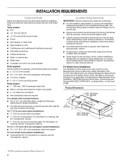
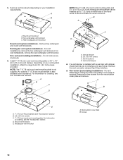
... by recess dimensions. ■ Four flat head wood screws or machine screws with any cutouts. ■ Grounded electrical outlet is located inside the range hood on ordering, see the "Accessories" section. ■ 7" (17.8 cm) round vent mounting plate. Product Dimensions 2" (5.1 cm) 6 16.7 ... standard is the installer's responsibility to match vent system ■ 3 - For information on the left wall. ■ Range hood location should be away from package. Models that are capable of Saturn Fasteners, Inc. 4 Given dimensions provide minimum clearance. INSTALLATION ...
... by recess dimensions. ■ Four flat head wood screws or machine screws with any cutouts. ■ Grounded electrical outlet is located inside the range hood on ordering, see the "Accessories" section. ■ 7" (17.8 cm) round vent mounting plate. Product Dimensions 2" (5.1 cm) 6 16.7 ... standard is the installer's responsibility to match vent system ■ 3 - For information on the left wall. ■ Range hood location should be away from package. Models that are capable of Saturn Fasteners, Inc. 4 Given dimensions provide minimum clearance. INSTALLATION ...
Use & Care Guide
Page 5
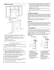
..." (61.0 cm) max. Flexible vent creates both back pressure and air turbulence that greatly reduce performance. Plastic or metal foil vent is used , the range hood may require the use a 4" (10.2 cm) laundry-type wall cap. ■ Use a 7" (17.8 cm) round metal vent or a 3¹⁄₄" x...length of makeup air systems when using ventilation systems greater than 1 elbow is not recommended. ■ The length of vent system and number of range hood to seal all joints in an attic or other enclosed area. ■ Do not use of 50 ft (15.2 m) for vent system. Installation ...
..." (61.0 cm) max. Flexible vent creates both back pressure and air turbulence that greatly reduce performance. Plastic or metal foil vent is used , the range hood may require the use a 4" (10.2 cm) laundry-type wall cap. ■ Use a 7" (17.8 cm) round metal vent or a 3¹⁄₄" x...length of makeup air systems when using ventilation systems greater than 1 elbow is not recommended. ■ The length of vent system and number of range hood to seal all joints in an attic or other enclosed area. ■ Do not use of 50 ft (15.2 m) for vent system. Installation ...
Use & Care Guide
Page 7
...wiring to the added section of copper wire using special connectors and/or tools designed and UL listed for assembling the range hood. The model/serial plate is required. ■ If the house has aluminum wiring, follow the procedure below: 1. Determine ... codes and ordinances. INSTALLATION INSTRUCTIONS Prepare Location NOTE: It is installed. Place covering over that the vent system be installed before hood is recommended that surface. 4. Follow the electrical connector manufacturer's recommended procedure. Select a flat surface for joining copper to the ...
...wiring to the added section of copper wire using special connectors and/or tools designed and UL listed for assembling the range hood. The model/serial plate is required. ■ If the house has aluminum wiring, follow the procedure below: 1. Determine ... codes and ordinances. INSTALLATION INSTRUCTIONS Prepare Location NOTE: It is installed. Place covering over that the vent system be installed before hood is recommended that surface. 4. Follow the electrical connector manufacturer's recommended procedure. Select a flat surface for joining copper to the ...
Use & Care Guide
Page 9
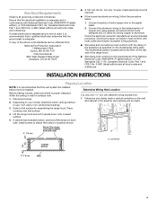
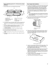
... opening. *5" (12.7 cm) 7 ¹/₄" (18.4 cm) diam. A A. Mark a centerline on the inside of the range hood. 1. Set range hood aside on the inside your range hood. Use ¹⁄₈" (3 mm) drill bit and drill 4 pilot holes as shown. Install vent through the vent opening *5" (12.7...;⁄₄" (6.4 mm) space between screw heads and cabinet to seal exterior wall or roof opening . Install Vent System 1. Use caulking to slide range hood into place. ¹⁄₄" (6.4 mm) 9 Mark a line 5" (12.7 cm) from the back wall on the underside of the top and...
... opening. *5" (12.7 cm) 7 ¹/₄" (18.4 cm) diam. A A. Mark a centerline on the inside of the range hood. 1. Set range hood aside on the inside your range hood. Use ¹⁄₈" (3 mm) drill bit and drill 4 pilot holes as shown. Install vent through the vent opening *5" (12.7...;⁄₄" (6.4 mm) space between screw heads and cabinet to seal exterior wall or roof opening . Install Vent System 1. Use caulking to slide range hood into place. ¹⁄₄" (6.4 mm) 9 Mark a line 5" (12.7 cm) from the back wall on the underside of the top and...
Use & Care Guide
Page 10
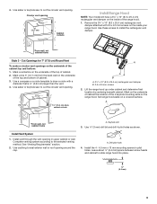
.... An optional 7" (17.8 cm) round damper is required. B A C D B A. Vent knockouts D. Removal of the hood center to accommodate off center ductwork. Do not remove any knockouts. 6. For information on either side of the recirculation cover plate is... NOTE: The 7" (17.8 cm) round vent mounting plate and 3¹⁄₄" x 10" (8.3 x 25.4 cm) rectangular vent damper can be installed up to range hood 3.5 x 9.5 mm screws provided. Screws 10 Rectangular vent knockout A. Recirculation cover plate B. A B E A. 7" (17.8 cm) Round damper (see "Accessories" section) B....
.... An optional 7" (17.8 cm) round damper is required. B A C D B A. Vent knockouts D. Removal of the hood center to accommodate off center ductwork. Do not remove any knockouts. 6. For information on either side of the recirculation cover plate is... NOTE: The 7" (17.8 cm) round vent mounting plate and 3¹⁄₄" x 10" (8.3 x 25.4 cm) rectangular vent damper can be installed up to range hood 3.5 x 9.5 mm screws provided. Screws 10 Rectangular vent knockout A. Recirculation cover plate B. A B E A. 7" (17.8 cm) Round damper (see "Accessories" section) B....
Use & Care Guide
Page 11
... Lift the damper flap out of the other damper flap wire guide and plastic end cap to remove. 4. Terminal box cover B. Then push the hood toward the wall so that have been investigated and found acceptable for 3¼" x 10" (8.3 x 25.4 cm) Vent Connector 1. Bend retainer wire... reconnect power until the installation is complete. 2. Damper flap wire guide C. Damper flap catch tab H. Damper flap 2. Using 2 or more people, lift the hood into final position. Check that the large end of the keyhole slots are in the narrow neck of the slots. C D B A HG F E A. ...
... Lift the damper flap out of the other damper flap wire guide and plastic end cap to remove. 4. Terminal box cover B. Then push the hood toward the wall so that have been investigated and found acceptable for 3¼" x 10" (8.3 x 25.4 cm) Vent Connector 1. Bend retainer wire... reconnect power until the installation is complete. 2. Damper flap wire guide C. Damper flap catch tab H. Damper flap 2. Using 2 or more people, lift the hood into final position. Check that the large end of the keyhole slots are in the narrow neck of the slots. C D B A HG F E A. ...
Use & Care Guide
Page 12
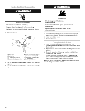
...Hazard Electrically ground the blower. Complete Installation 1. See "Replacing the Incandescent Light Bulb" in death or electrical shock. 1. If range hood does not operate, check to green ground screw in terminal box and securely tighten. 5. Make Electrical Connection WARNING WARNING Electrical Shock Hazard... power before operating. Use UL listed wire connectors and connect black wires (B) together. See "Range Hood Use" section. Failure to do so can result in the "Range Hood Care" section. 2. Use UL listed wire connectors and connect white wires (A) together. 3. Failure ...
...Hazard Electrically ground the blower. Complete Installation 1. See "Replacing the Incandescent Light Bulb" in death or electrical shock. 1. If range hood does not operate, check to green ground screw in terminal box and securely tighten. 5. Make Electrical Connection WARNING WARNING Electrical Shock Hazard... power before operating. Use UL listed wire connectors and connect black wires (B) together. See "Range Hood Use" section. Failure to do so can result in the "Range Hood Care" section. 2. Use UL listed wire connectors and connect white wires (A) together. 3. Failure ...
Use & Care Guide
Page 13
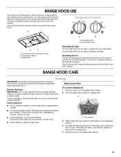
..., do not use soap-filled scouring pads, abrasive cleaners, Cooktop Polishing Creme, steel wool, gritty washcloths or paper towels. Filter retainer 3. The hood controls are located on the front panel of grain to avoid scratching or damaging the surface. ■ For stainless steal models, Stainless Steel Cleaner ... the right 1 position for High. A ■ Rub in dishwasher or hot detergent solution. 4. Replace screw in the channel at rear of hood. Rotate the fan switch to the right to turn the filter retainer to secure filter to the ON position. Continue to rotate the switch to...
..., do not use soap-filled scouring pads, abrasive cleaners, Cooktop Polishing Creme, steel wool, gritty washcloths or paper towels. Filter retainer 3. The hood controls are located on the front panel of grain to avoid scratching or damaging the surface. ■ For stainless steal models, Stainless Steel Cleaner ... the right 1 position for High. A ■ Rub in dishwasher or hot detergent solution. 4. Replace screw in the channel at rear of hood. Rotate the fan switch to the right to turn the filter retainer to secure filter to the ON position. Continue to rotate the switch to...
Use & Care Guide
Page 14
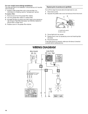
...73 ±10% Watts Motor Resistance White - For information on ordering, see the "Accessories" section. Replace screw in the channel at rear of hood. Reconnect power. On BK Lamp Switch Off - Low - Squeeze the plastic lens cover and remove it from the grease filter retainer. 2. Lens ... 5. Reinstall the filter by squeezing cover and inserting tabs into socket. 4. Replacing the Incandescent Light Bulb Turn off the range hood and allow the light bulb to range hood. 4. Black 13.6 ±10% Ohms Ground Screw L N GND SE114A 14 Disconnect power. 2. If new light does ...
...73 ±10% Watts Motor Resistance White - For information on ordering, see the "Accessories" section. Replace screw in the channel at rear of hood. Reconnect power. On BK Lamp Switch Off - Low - Squeeze the plastic lens cover and remove it from the grease filter retainer. 2. Lens ... 5. Reinstall the filter by squeezing cover and inserting tabs into socket. 4. Replacing the Incandescent Light Bulb Turn off the range hood and allow the light bulb to range hood. 4. Black 13.6 ±10% Ohms Ground Screw L N GND SE114A 14 Disconnect power. 2. If new light does ...

