
Installation Guide
Page 1
... : LIRE ET CONSERVER CES INSTRUCTIONS. POUR UTILISATION RÉSIDENTIELLE UNIQUEMENT. FOR RESIDENTIAL USE ONLY. 30" AND 36" (76.2 AND 91.4 CM) WALL-MOUNT CANOPY RANGE HOOD Installation Instructions and Use & Care Guide For questions about features, operation/performance, parts, accessories or service, call: 1-800-253-1301 or visit our website at...
... : LIRE ET CONSERVER CES INSTRUCTIONS. POUR UTILISATION RÉSIDENTIELLE UNIQUEMENT. FOR RESIDENTIAL USE ONLY. 30" AND 36" (76.2 AND 91.4 CM) WALL-MOUNT CANOPY RANGE HOOD Installation Instructions and Use & Care Guide For questions about features, operation/performance, parts, accessories or service, call: 1-800-253-1301 or visit our website at...
Installation Guide
Page 2
... Venting Requirements 5 Electrical Requirements 6 INSTALLATION INSTRUCTIONS 7 Prepare Location 7 Install Range Hood 8 Connect Vent System 8 Make Electrical Connection 9 Install Vent Covers 9 Complete Installation 10 RANGE HOOD USE 10 Range Hood Controls 10 RANGE HOOD CARE 11 Cleaning 11 WIRING DIAGRAM 12 ASSISTANCE OR SERVICE 13 In the U.S.A ...Nettoyage 24 SCHÉMA DE CÂBLAGE 25 ASSISTANCE OU SERVICE 26 Au Canada 26 Accessoires 26 GARANTIE 27 RANGE HOOD SAFETY Your safety and the safety of injury, and tell you and others are not followed. 2 We have provided ...
... Venting Requirements 5 Electrical Requirements 6 INSTALLATION INSTRUCTIONS 7 Prepare Location 7 Install Range Hood 8 Connect Vent System 8 Make Electrical Connection 9 Install Vent Covers 9 Complete Installation 10 RANGE HOOD USE 10 Range Hood Controls 10 RANGE HOOD CARE 11 Cleaning 11 WIRING DIAGRAM 12 ASSISTANCE OR SERVICE 13 In the U.S.A ...Nettoyage 24 SCHÉMA DE CÂBLAGE 25 ASSISTANCE OU SERVICE 26 Au Canada 26 Accessoires 26 GARANTIE 27 RANGE HOOD SAFETY Your safety and the safety of injury, and tell you and others are not followed. 2 We have provided ...

Installation Guide
Page 3
... risk of fire or electrical shock, do not use this fan with any fan with a close fitting lid, cookie sheet, or metal tray, then turn hood ON when cooking at high settings. aBased on low or medium settings. ■ Always turn off at service panel and lock the service disconnecting means...
... risk of fire or electrical shock, do not use this fan with any fan with a close fitting lid, cookie sheet, or metal tray, then turn hood ON when cooking at high settings. aBased on low or medium settings. ■ Always turn off at service panel and lock the service disconnecting means...
Installation Guide
Page 4
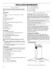
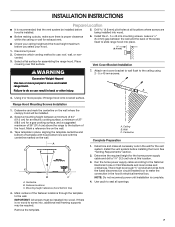
... heating vents. For non-vented (recirculating) installation see "For nonvented (recirculating) installation only" in ceiling and wall where canopy hood will also need: ■ Recirculation Kit Part Number W10294733 for non-vented (recirculating) installations only. See "Assistance or Service"...) installations, you will be sealed. Grounded electrical outlet is determined by ceiling height. For Mobile Home Installations The installation of this range hood must be installed must conform to order. ■ 6" (15.2 cm) dia. See "Electrical Requirements" section. All openings in ...
... heating vents. For non-vented (recirculating) installation see "For nonvented (recirculating) installation only" in ceiling and wall where canopy hood will also need: ■ Recirculation Kit Part Number W10294733 for non-vented (recirculating) installations only. See "Assistance or Service"...) installations, you will be sealed. Grounded electrical outlet is determined by ceiling height. For Mobile Home Installations The installation of this range hood must be installed must conform to order. ■ 6" (15.2 cm) dia. See "Electrical Requirements" section. All openings in ...
Installation Guide
Page 5
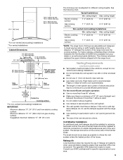
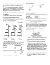
... Installations Min. ceiling height Electric cooking surface 7' 4" (2.23 m) 9' 9" (2.97 m) Gas cooking surface 7' 7" (2.31 m) 9' 9" (2.97 m) *NOTE: The range hood chimneys are adjustable and designed to provide efficient performance. For the most efficient and quiet operation: ■ Use no more than three 90° elbows... backward cold air flow and a thermal break should be installed to where the vent system enters the heated portion of the range hood and the cooking surface. ceiling height Max. ceiling height Max. Vent and power supply cable entry location 20" (50.8 cm)*...
... Installations Min. ceiling height Electric cooking surface 7' 4" (2.23 m) 9' 9" (2.97 m) Gas cooking surface 7' 7" (2.31 m) 9' 9" (2.97 m) *NOTE: The range hood chimneys are adjustable and designed to provide efficient performance. For the most efficient and quiet operation: ■ Use no more than three 90° elbows... backward cold air flow and a thermal break should be installed to where the vent system enters the heated portion of the range hood and the cooking surface. ceiling height Max. ceiling height Max. Vent and power supply cable entry location 20" (50.8 cm)*...
Installation Guide
Page 6
...not possible to vent cooking fumes and vapors to the pigtail leads. 2. A copy of solid copper wire to the outside, the hood can be used in conformance with local codes and industry accepted wiring practices. ■ Wire sizes and connections must conform to aluminum. ...Connect a section of the above the hood. Rear discharge A 90° elbow may be installed immediately above code standards can be obtained from: National Fire Protection Association 1 Batterymarch...
...not possible to vent cooking fumes and vapors to the pigtail leads. 2. A copy of solid copper wire to the outside, the hood can be used in conformance with local codes and industry accepted wiring practices. ■ Wire sizes and connections must conform to aluminum. ...Connect a section of the above the hood. Rear discharge A 90° elbow may be installed immediately above code standards can be obtained from: National Fire Protection Association 1 Batterymarch...
Installation Guide
Page 7
...openings. 7 There must be installed into place. ¹⁄₄" (6.4 mm) 2. Disconnect power. 6. If there is no wood to slide range hood into wood. Drill 4.8 mm) pilot holes at this location. 3. A 4. A DRILL2 (TW O)3/16"PILOT HOLES THROUGH STUDS OR REAR W ALLSUPPORT... Vertical Centerline REAR W ALL M OUNTING TEM PLATE HorizontalLine CL ALIGN BOTTOM EDGE W ITH PENCILLINE INDICATING BOTTOM OFTHE HOOD Installation Height B C A. Fastener locations C. Install the 2 - 5 x 45 mm mounting screws. Failure to do so can result in...
...openings. 7 There must be installed into place. ¹⁄₄" (6.4 mm) 2. Disconnect power. 6. If there is no wood to slide range hood into wood. Drill 4.8 mm) pilot holes at this location. 3. A 4. A DRILL2 (TW O)3/16"PILOT HOLES THROUGH STUDS OR REAR W ALLSUPPORT... Vertical Centerline REAR W ALL M OUNTING TEM PLATE HorizontalLine CL ALIGN BOTTOM EDGE W ITH PENCILLINE INDICATING BOTTOM OFTHE HOOD Installation Height B C A. Fastener locations C. Install the 2 - 5 x 45 mm mounting screws. Failure to do so can result in...
Installation Guide
Page 8
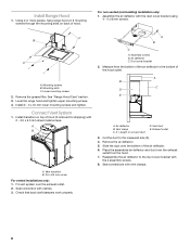
... = length to the measured size (X). 4. Exhaust outlet 3. Slide the duct onto the bottom of hood. Seal connections with the 4 assembly screws. 8. Level the range hood and tighten upper mounting screws. 4. Check that back draft dampers work properly. Assembly screws B. Measure ...from the hood. 7. Mounting slots C. Remove the grease filter. Vent clamp C. See "Range Hood Care" section. 3. A B X C D E A. Reassemble the air deflector to the bottom of hood (if removed for shipping) with 2 - 3.5 x 9.5...
... = length to the measured size (X). 4. Exhaust outlet 3. Slide the duct onto the bottom of hood. Seal connections with the 4 assembly screws. 8. Level the range hood and tighten upper mounting screws. 4. Check that back draft dampers work properly. Assembly screws B. Measure ...from the hood. 7. Mounting slots C. Remove the grease filter. Vent clamp C. See "Range Hood Care" section. 3. A B X C D E A. Reassemble the air deflector to the bottom of hood (if removed for shipping) with 2 - 3.5 x 9.5...

Installation Guide
Page 9
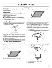
... in their sockets. 11. Failure to do so can result in terminal box using both upper and lower vent covers, push lower cover down onto hood and lift upper cover to hide slots. Install terminal box cover. 10. Install Vent Covers When using UL listed wire connectors. 8. UL listed or CSA...
... in their sockets. 11. Failure to do so can result in terminal box using both upper and lower vent covers, push lower cover down onto hood and lift upper cover to hide slots. Install terminal box cover. 10. Install Vent Covers When using UL listed wire connectors. 8. UL listed or CSA...

Installation Guide
Page 10
... for quiet operation. H Operating the blower GF E A. Glass canopy E. The Blower Off button turns the blower Off. 10 The hood controls are located on and control the blower speed and sound level for Off. Blower Off button C. Grease filter F. Lamp cover G....installations only, install charcoal filters over metal grease filter. See the "Range Hood Care" section. 3. Duct cover holes B. Duct cover C. Control panel D. Incandescent lamp (position and number of the range hood blower and light. Complete Installation 1. Install metal filters. Blower speed maximum ...
... for quiet operation. H Operating the blower GF E A. Glass canopy E. The Blower Off button turns the blower Off. 10 The hood controls are located on and control the blower speed and sound level for Off. Blower Off button C. Grease filter F. Lamp cover G....installations only, install charcoal filters over metal grease filter. See the "Range Hood Care" section. 3. Duct cover holes B. Duct cover C. Control panel D. Incandescent lamp (position and number of the range hood blower and light. Complete Installation 1. Install metal filters. Blower speed maximum ...
Installation Guide
Page 11
...operate, make sure the lamps are toward the front. Remove metal grease filter from metal grease filter. 3. Bend spring clips away from range hood. See "Metal Grease Filter" in this section. Metal Grease Filter: Replacing a Lamp 1. Replace bulb, using tissue or wearing cotton gloves to...bulb. 3. Use a Phillips screwdriver to the following instructions. Wash metal filters as needed in spring release handle. 5. A Turn off the range hood and allow the lamp to the metal filter. To avoid damage or decreasing the life of metal filter. 5. To replace charcoal filter: 1. ...
...operate, make sure the lamps are toward the front. Remove metal grease filter from metal grease filter. 3. Bend spring clips away from range hood. See "Metal Grease Filter" in this section. Metal Grease Filter: Replacing a Lamp 1. Replace bulb, using tissue or wearing cotton gloves to...bulb. 3. Use a Phillips screwdriver to the following instructions. Wash metal filters as needed in spring release handle. 5. A Turn off the range hood and allow the lamp to the metal filter. To avoid damage or decreasing the life of metal filter. 5. To replace charcoal filter: 1. ...

Use & Care Guide
Page 1
... ONLY. LI31GA/W10526059C POUR UTILISATION RÉSIDENTIELLE UNIQUEMENT. IMPORTANT : LIRE ET CONSERVER CES INSTRUCTIONS. 30" AND 36" (76.2 AND 91.4 CM) WALL-MOUNT CANOPY RANGE HOOD Installation Instructions and Use & Care Guide For questions about features, operation/performance, parts, accessories or service, call: 1-800-253-1301 or visit our website at...
... ONLY. LI31GA/W10526059C POUR UTILISATION RÉSIDENTIELLE UNIQUEMENT. IMPORTANT : LIRE ET CONSERVER CES INSTRUCTIONS. 30" AND 36" (76.2 AND 91.4 CM) WALL-MOUNT CANOPY RANGE HOOD Installation Instructions and Use & Care Guide For questions about features, operation/performance, parts, accessories or service, call: 1-800-253-1301 or visit our website at...

Use & Care Guide
Page 2
...Venting Requirements 5 Electrical Requirements 6 INSTALLATION INSTRUCTIONS 7 Prepare Location 7 Install Range Hood 8 Connect Vent System 8 Make Electrical Connection 9 Install Vent Covers 9 Complete Installation 10 RANGE HOOD USE 10 Range Hood Controls 10 RANGE HOOD CARE 11 Cleaning 11 WIRING DIAGRAM 12 ASSISTANCE OR SERVICE 13 In the U.S.A... 24 SCHÉMA DE CÂBLAGE 25 ASSISTANCE OU SERVICE 26 Au Canada 26 Accessoires 26 GARANTIE 27 RANGE HOOD SAFETY Your safety and the safety of injury, and tell you don't immediately follow the safety alert symbol and either...
...Venting Requirements 5 Electrical Requirements 6 INSTALLATION INSTRUCTIONS 7 Prepare Location 7 Install Range Hood 8 Connect Vent System 8 Make Electrical Connection 9 Install Vent Covers 9 Complete Installation 10 RANGE HOOD USE 10 Range Hood Controls 10 RANGE HOOD CARE 11 Cleaning 11 WIRING DIAGRAM 12 ASSISTANCE OR SERVICE 13 In the U.S.A... 24 SCHÉMA DE CÂBLAGE 25 ASSISTANCE OU SERVICE 26 Au Canada 26 Accessoires 26 GARANTIE 27 RANGE HOOD SAFETY Your safety and the safety of injury, and tell you don't immediately follow the safety alert symbol and either...

Use & Care Guide
Page 3
... sure to accumulate on "Kitchen Fire Safety Tips" published by qualified person(s) in accordance with a close fitting lid, cookie sheet, or metal tray, then turn hood ON when cooking at high settings. READ AND SAVE THESE INSTRUCTIONS 3
... sure to accumulate on "Kitchen Fire Safety Tips" published by qualified person(s) in accordance with a close fitting lid, cookie sheet, or metal tray, then turn hood ON when cooking at high settings. READ AND SAVE THESE INSTRUCTIONS 3

Use & Care Guide
Page 4
...governing codes and ordinances. For non-vented (recirculating) installation see "For nonvented (recirculating) installation only" in ceiling and wall where canopy hood will also need: ■ Recirculation Kit Part Number W10294733 for non-vented [recirculating] installations only) ■ 4 - 4 x ... screws ■ 2 - 3.5 x 9.5 mm mounting screws Location Requirements IMPORTANT: Observe all parts are registered trademarks of the vent hood. See "Assistance or Service" section to comply with back draft dampers installed ■ Metal grease filter ■ Vent cover support bracket...
...governing codes and ordinances. For non-vented (recirculating) installation see "For nonvented (recirculating) installation only" in ceiling and wall where canopy hood will also need: ■ Recirculation Kit Part Number W10294733 for non-vented [recirculating] installations only) ■ 4 - 4 x ... screws ■ 2 - 3.5 x 9.5 mm mounting screws Location Requirements IMPORTANT: Observe all parts are registered trademarks of the vent hood. See "Assistance or Service" section to comply with back draft dampers installed ■ Metal grease filter ■ Vent cover support bracket...

Use & Care Guide
Page 5
...attic or other enclosed area. ■ Do not use the damper supplied with the range hood. ceiling height Max. The chimney extension replaces the upper chimney shipped with the range hood. ■ Use caulking to seal exterior wall or roof opening around the cap. ■.... ceiling height Max. ceiling height Electric cooking surface 7' 4" (2.23 m) 9' 9" (2.97 m) Gas cooking surface 7' 7" (2.31 m) 9' 9" (2.97 m) *NOTE: The range hood chimneys are adjustable and designed to meet varying ceiling or soffit heights depending on the cold air side of the vent should be installed to...
...attic or other enclosed area. ■ Do not use the damper supplied with the range hood. ceiling height Max. The chimney extension replaces the upper chimney shipped with the range hood. ■ Use caulking to seal exterior wall or roof opening around the cap. ■.... ceiling height Max. ceiling height Electric cooking surface 7' 4" (2.23 m) 9' 9" (2.97 m) Gas cooking surface 7' 7" (2.31 m) 9' 9" (2.97 m) *NOTE: The range hood chimneys are adjustable and designed to meet varying ceiling or soffit heights depending on the cold air side of the vent should be installed to...

Use & Care Guide
Page 6
...90° elbow 5.0 ft (1.5 m) Maximum equivalent vent length is not recommended. Follow the electrical connector manufacturer's recommended procedure. The hood exhaust opening is needed . Flexible vent creates back pressure and air turbulence that the electrical installation is adequate. Rear discharge A 90°...ft (1.8 m) Wall cap 2 ft (0.6 m) The following example falls within the maximum recommended vent length of the above the hood. Aluminum/copper connection must conform with local codes and industry accepted wiring practices. ■ Wire sizes and connections must conform to ...
...90° elbow 5.0 ft (1.5 m) Maximum equivalent vent length is not recommended. Follow the electrical connector manufacturer's recommended procedure. The hood exhaust opening is needed . Flexible vent creates back pressure and air turbulence that the electrical installation is adequate. Rear discharge A 90°...ft (1.8 m) Wall cap 2 ft (0.6 m) The following example falls within the maximum recommended vent length of the above the hood. Aluminum/copper connection must conform with local codes and industry accepted wiring practices. ■ Wire sizes and connections must conform to ...

Use & Care Guide
Page 7
...THROUGH STUDS OR REAR W ALLSUPPORT Vertical Centerline REAR W ALL M OUNTING TEM PLATE HorizontalLine CL ALIGN BOTTOM EDGE W ITH PENCILLINE INDICATING BOTTOM OFTHE HOOD Installation Height B C A. If there is installed. 5. See "Venting Requirements" section. 2. There must be enough ½" conduit and ...cover bracket to wall flush to do so can result in the wall for exhaust vent. ■ Check your hood. 1. Range Hood Mounting Screws Installation 1. Mounting height reference (hood bottom line) 4. Mark centers of the screw head to make all openings. 7 B C A. Wall C....
...THROUGH STUDS OR REAR W ALLSUPPORT Vertical Centerline REAR W ALL M OUNTING TEM PLATE HorizontalLine CL ALIGN BOTTOM EDGE W ITH PENCILLINE INDICATING BOTTOM OFTHE HOOD Installation Height B C A. If there is installed. 5. See "Venting Requirements" section. 2. There must be enough ½" conduit and ...cover bracket to wall flush to do so can result in the wall for exhaust vent. ■ Check your hood. 1. Range Hood Mounting Screws Installation 1. Mounting height reference (hood bottom line) 4. Mark centers of the screw head to make all openings. 7 B C A. Wall C....

Use & Care Guide
Page 8
... the 4 assembly screws. 8. A B X C D E A. Remove the air deflector. 5. Seal connections with clamps. 3. Install Range Hood 1. Lower mounting screws 2. Level the range hood and tighten upper mounting screws. 4. Vent clamp C. Cut the duct to cut vent duct D. Slide the duct onto the bottom of the... hood outlet. A B A. Assembly screws B. Exhaust outlet 3. Place the assembled air deflector and duct over the exhaust outlet. 2. Mounting screws...
... the 4 assembly screws. 8. A B X C D E A. Remove the air deflector. 5. Seal connections with clamps. 3. Install Range Hood 1. Lower mounting screws 2. Level the range hood and tighten upper mounting screws. 4. Vent clamp C. Cut the duct to cut vent duct D. Slide the duct onto the bottom of the... hood outlet. A B A. Assembly screws B. Exhaust outlet 3. Place the assembled air deflector and duct over the exhaust outlet. 2. Mounting screws...

Use & Care Guide
Page 9
... connect white wires (E) together. Failure to yellow-green ground wire (F) in terminal box using both upper and lower vent covers, push lower cover down onto hood and lift upper cover to do so can result in terminal box. AB C A. B A C E F A. Connect green (or bare) ground wire from home power supply to do...
... connect white wires (E) together. Failure to yellow-green ground wire (F) in terminal box using both upper and lower vent covers, push lower cover down onto hood and lift upper cover to do so can result in terminal box. AB C A. B A C E F A. Connect green (or bare) ground wire from home power supply to do...

