

Warranty Information
Page 1
... requires repair. instructions attached to correct defects in fixtures (i.e. Specified Replacement Parts and repair 4. warranty period. 9. the United States or Canada and 13. Service or parts for Factory 3. This warranty gives you specific legal rights, and you should ask Whirlpool or your retailer about the quality, durability, or need for 8. labor to or furnished with electrical or plumbing codes or correction of the product. 15. gas. 7. Repairs to parts...
... requires repair. instructions attached to correct defects in fixtures (i.e. Specified Replacement Parts and repair 4. warranty period. 9. the United States or Canada and 13. Service or parts for Factory 3. This warranty gives you specific legal rights, and you should ask Whirlpool or your retailer about the quality, durability, or need for 8. labor to or furnished with electrical or plumbing codes or correction of the product. 15. gas. 7. Repairs to parts...
Installation Guide
Page 3
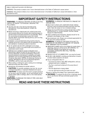
... ventilating use to exhaust hazardous or explosive materials and vapors. BE CAREFUL TO PREVENT BURNS. READ AND SAVE THESE INSTRUCTIONS 3 I Before servicing or cleaning the unit, switch power off the burner. Grease should not be locked, securely fasten a prominent warning device, such as those published by qualified person(s) in accordance with a damaged cord or plug. You can fight the fire with any fan...
... ventilating use to exhaust hazardous or explosive materials and vapors. BE CAREFUL TO PREVENT BURNS. READ AND SAVE THESE INSTRUCTIONS 3 I Before servicing or cleaning the unit, switch power off the burner. Grease should not be locked, securely fasten a prominent warning device, such as those published by qualified person(s) in accordance with a damaged cord or plug. You can fight the fire with any fan...
Installation Guide
Page 4
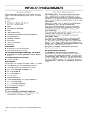
...be installed must be used. Location Requirements IMPORTANT: Observe all parts are shown must be away from strong draft areas, such as required For non-vented (recirculating) installations, you will need : ■■ 1 wall or roof cap Parts supplied Remove parts from your cooktop/range manufacturer installation instructions before starting installation. Have a qualified technician install the range hood. Cabinet opening dimensions that all governing codes and ordinances. Grounded electrical outlet is located inside the liner behind the filter on the model/serial rating plate...
...be installed must be used. Location Requirements IMPORTANT: Observe all parts are shown must be away from strong draft areas, such as required For non-vented (recirculating) installations, you will need : ■■ 1 wall or roof cap Parts supplied Remove parts from your cooktop/range manufacturer installation instructions before starting installation. Have a qualified technician install the range hood. Cabinet opening dimensions that all governing codes and ordinances. Grounded electrical outlet is located inside the liner behind the filter on the model/serial rating plate...

Installation Guide
Page 5
... installation manual for nonvented (recirculating) installations. ■■ Do not terminate the vent system in the vent system. ■■ Use caulking to selecting your cabinet dimensions prior to seal exterior wall or roof opening around the cap. ■■ The size of cabinet to the outside, except for specific application. Check your vent hood. For the most efficient and quiet operation: ■■ Use no more than three 90° elbows...
... installation manual for nonvented (recirculating) installations. ■■ Do not terminate the vent system in the vent system. ■■ Use caulking to selecting your cabinet dimensions prior to seal exterior wall or roof opening around the cap. ■■ The size of cabinet to the outside, except for specific application. Check your vent hood. For the most efficient and quiet operation: ■■ Use no more than three 90° elbows...

Installation Guide
Page 6
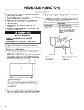
... used in your HVAC professional for installation is recommended. Soffit D. 6" (15.2 cm) vent E. Range hood F. cabinet height I E E H A. Makeup air Local building codes may allow the 6" (15.2 cm) vent and vent cover to be seen. 90° elbow 5.0 ft (1.5 m) 6 Roof cap A. 6" (15.2 cm) vent through the roof B. Charcoal Filter Kit is 6" (15.2 cm) round vent with greater than three 90° elbows. See the "Assistance or Service" section to order. Wall H. 12" (30.5 cm) min. Wall cap Calculate Vent System Length...
... used in your HVAC professional for installation is recommended. Soffit D. 6" (15.2 cm) vent E. Range hood F. cabinet height I E E H A. Makeup air Local building codes may allow the 6" (15.2 cm) vent and vent cover to be seen. 90° elbow 5.0 ft (1.5 m) 6 Roof cap A. 6" (15.2 cm) vent through the roof B. Charcoal Filter Kit is 6" (15.2 cm) round vent with greater than three 90° elbows. See the "Assistance or Service" section to order. Wall H. 12" (30.5 cm) min. Wall cap Calculate Vent System Length...

Installation Guide
Page 7
.... This range hood is required. Do not use an extension cord. or 20-amp, fused electrical circuit is equipped with a grounding plug. If a mating outlet is not available, it is recommended that a qualified electrical installer determine that is equipped with a power supply cord having a grounding wire with a cord having a 3 prong grounding plug. SAVE THESE INSTRUCTIONS 7 Do not use an adapter. 337/16" (85 cm) Do not use an extension cord. The...
.... This range hood is required. Do not use an extension cord. or 20-amp, fused electrical circuit is equipped with a grounding plug. If a mating outlet is not available, it is recommended that a qualified electrical installer determine that is equipped with a power supply cord having a grounding wire with a cord having a 3 prong grounding plug. SAVE THESE INSTRUCTIONS 7 Do not use an adapter. 337/16" (85 cm) Do not use an extension cord. The...
Installation Guide
Page 8
... of cabinet cutout B. A B* C D 4. Centerline A C B A. Determine which venting method to move and install range hood. Place covering over that the vent system be installed before the range hood is installed. ■■ Before making cutouts, make sure there is required for damper transition clearance. Using two or more people to use: roof, wall, or non-vented. 3. Complete cabinet preparation following the instructions for some types of cabinets (see Step 3 in the cabinet top is proper clearance within the ceiling or wall for vent...
... of cabinet cutout B. A B* C D 4. Centerline A C B A. Determine which venting method to move and install range hood. Place covering over that the vent system be installed before the range hood is installed. ■■ Before making cutouts, make sure there is required for damper transition clearance. Using two or more people to use: roof, wall, or non-vented. 3. Complete cabinet preparation following the instructions for some types of cabinets (see Step 3 in the cabinet top is proper clearance within the ceiling or wall for vent...

Installation Guide
Page 9
... of the cabinet. 4. Use a saber saw or keyhole saw to cut a round opening is required. Centerline C. 6¼" (15.9 cm) round cutout A. B A C D A. Install transition on installing charcoal filters. Range hood liner 3. Mark the cutout as shown. The Recirculation Kit must be vented indoors through the top of the cabinet. Measure from the underside of the vent opening (A). Vent transition B. 3.5 x 9.5 mm screws 9 Cabinet Height 15" (38.1 cm) A Hole Shape and Size A 6¼" (15.9 cm) diameter round opening C. B A A. Remove the vent duct from the...
... of the cabinet. 4. Use a saber saw or keyhole saw to cut a round opening is required. Centerline C. 6¼" (15.9 cm) round cutout A. B A C D A. Install transition on installing charcoal filters. Range hood liner 3. Mark the cutout as shown. The Recirculation Kit must be vented indoors through the top of the cabinet. Measure from the underside of the vent opening (A). Vent transition B. 3.5 x 9.5 mm screws 9 Cabinet Height 15" (38.1 cm) A Hole Shape and Size A 6¼" (15.9 cm) diameter round opening C. B A A. Remove the vent duct from the...

Installation Guide
Page 10
Ceiling B. Range hood Through Soffit: F. vent cover height Recirculating through the cabinet top wall A A B G D F EI H A. Consider the cutout chart measures to cut a 5¾" (14.6 cm) hole for damper transition clearance. 3. Complete Preparation Installation brackets configuration To assemble the installation brackets, you must consider the cabinet's material thickness and your cabinet material thickness, then locate the bracket's installation holes, based on the cabinet. Cabinet G. Mark the location and use a saber saw or keyhole saw to make the openings on your...
Ceiling B. Range hood Through Soffit: F. vent cover height Recirculating through the cabinet top wall A A B G D F EI H A. Consider the cutout chart measures to cut a 5¾" (14.6 cm) hole for damper transition clearance. 3. Complete Preparation Installation brackets configuration To assemble the installation brackets, you must consider the cabinet's material thickness and your cabinet material thickness, then locate the bracket's installation holes, based on the cabinet. Cabinet G. Mark the location and use a saber saw or keyhole saw to make the openings on your...
Installation Guide
Page 11
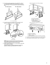
... bottom of the cabinet, and tighten. Washers (optional) D. Screws - 4.5 x 13 mm (8) C. Install the vent system according to seal the exterior wall or roof opening. 11 Bracket Orientation for 36" [91.4 cm] cabinet) 5. Orient the brackets depending on the selected thickness hole. 30" width cabinet 36" width cabinet A A A. 4 x 15 mm screws 3. Screws - 4.5 x 13 mm (8) C. C A A. 36" (91.4 cm) cabinet B. Use caulking to the method needed. 6. Using the bracket as depicted in...
... bottom of the cabinet, and tighten. Washers (optional) D. Screws - 4.5 x 13 mm (8) C. Install the vent system according to seal the exterior wall or roof opening. 11 Bracket Orientation for 36" [91.4 cm] cabinet) 5. Orient the brackets depending on the selected thickness hole. 30" width cabinet 36" width cabinet A A A. 4 x 15 mm screws 3. Screws - 4.5 x 13 mm (8) C. C A A. 36" (91.4 cm) cabinet B. Use caulking to the method needed. 6. Using the bracket as depicted in...

Installation Guide
Page 12
... canopy assembly in the front side of the cabinet. Lamp wire B. Motor box wire A. Cabinet B. A A. Motor box wire 12 Install Range Hood WARNING Excessive Weight Hazard Use two or more people, lift the hood liner into the cabinet until it through the bracket as depicted in back or other injury. 1. Open perimetric panel and remove the metal grease filters from the lower canopy assembly into the connectors located inside the hood liner. Attach the 4.2 x 8 mm (8) screws into the mounting bracket and tighten all mounting screws...
... canopy assembly in the front side of the cabinet. Lamp wire B. Motor box wire A. Cabinet B. A A. Motor box wire 12 Install Range Hood WARNING Excessive Weight Hazard Use two or more people, lift the hood liner into the cabinet until it through the bracket as depicted in back or other injury. 1. Open perimetric panel and remove the metal grease filters from the lower canopy assembly into the connectors located inside the hood liner. Attach the 4.2 x 8 mm (8) screws into the mounting bracket and tighten all mounting screws...
Installation Guide
Page 13
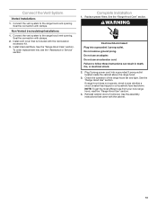
...the range hood vent opening . NOTE: To get the most efficient use an adapter. Use the assembly instructions that is included with the cabinet. 13 Non-Vented (recirculating) Installations 1. Install vent cover that came with the recirculation accessory kit. 3. See the "Range Hood Care" section. Replace grease filters. Do not use from your new range hood, read the "Range Hood Use" section. 4. Check the operation of the range hood fan and light. If range hood does not operate, check to the range hood vent opening . Complete Installation 1. See the "Range Hood Care" section...
...the range hood vent opening . NOTE: To get the most efficient use an adapter. Use the assembly instructions that is included with the cabinet. 13 Non-Vented (recirculating) Installations 1. Install vent cover that came with the recirculation accessory kit. 3. See the "Range Hood Care" section. Replace grease filters. Do not use from your new range hood, read the "Range Hood Use" section. 4. Check the operation of the range hood fan and light. If range hood does not operate, check to the range hood vent opening . Complete Installation 1. See the "Range Hood Care" section...

Installation Guide
Page 14
... fan button light will turn the fan on at LOW speed. The fan will run on the temperature Auto Sense is measuring. ■■ Auto Sense can be set temperature limit, C the fan will turn the fan on . Hood liner Range Hood Controls To Deactivate Auto Sense: ■■ If the Auto Fan button is running to turn on automatically when it to operate several minutes after the cooking is changed to the gas cooktop...
... fan button light will turn the fan on at LOW speed. The fan will run on the temperature Auto Sense is measuring. ■■ Auto Sense can be set temperature limit, C the fan will turn the fan on . Hood liner Range Hood Controls To Deactivate Auto Sense: ■■ If the Auto Fan button is running to turn on automatically when it to operate several minutes after the cooking is changed to the gas cooktop...

Installation Guide
Page 15
... catches to the exterior surface, do not use . Pull the spring release handle down the filter. A A. Replace with the charcoal filter so that the slots on the filter correspond to the pins on metal filter and release handle to the following instructions. AB C A. RANGE HOOD CARE Cleaning IMPORTANT: Clean the hood and grease filters frequently according to latch into upper track. 5. Replace grease filter before operating hood. See the "Accessories" section for information...
... catches to the exterior surface, do not use . Pull the spring release handle down the filter. A A. Replace with the charcoal filter so that the slots on the filter correspond to the pins on metal filter and release handle to the following instructions. AB C A. RANGE HOOD CARE Cleaning IMPORTANT: Clean the hood and grease filters frequently according to latch into upper track. 5. Replace grease filter before operating hood. See the "Accessories" section for information...

Installation Guide
Page 16
...POWER ABSORTION PUISSANCE NOMINALE 240 W MOTOR RESISTANCE (Ohms) RÉSISTANCE DU MOTEUR (Ohms) BLUE - GREY 27.1 BLEU - WIRING DIAGRAM User Interface Interface Utilisateur AUTO-SPEED SENSOR CAPTEUR DE VITESSE AUTOMATIQUE GND PWM BK - BL L N C 2 N La1 3 1 4 12 BK - N WH - JA/VE WH - BU RD - BL BK - N RD - N DIMMABLE LED DRIVER... R LED BK - JA/VE BK - N RD - BLACK 17.7 BLEU - ROUGE 34,6 BLUE - JA Electronic Power Board Carte Électronique de Puissance YL/GN - N FILTER YL/GN - BL EMI BK - N RD - R RL4 RL5 RL3 RL2 RL1 La2 N BU - BL FILTRE ...
...POWER ABSORTION PUISSANCE NOMINALE 240 W MOTOR RESISTANCE (Ohms) RÉSISTANCE DU MOTEUR (Ohms) BLUE - GREY 27.1 BLEU - WIRING DIAGRAM User Interface Interface Utilisateur AUTO-SPEED SENSOR CAPTEUR DE VITESSE AUTOMATIQUE GND PWM BK - BL L N C 2 N La1 3 1 4 12 BK - N WH - JA/VE WH - BU RD - BL BK - N RD - N DIMMABLE LED DRIVER... R LED BK - JA/VE BK - N RD - BLACK 17.7 BLEU - ROUGE 34,6 BLUE - JA Electronic Power Board Carte Électronique de Puissance YL/GN - N FILTER YL/GN - BL EMI BK - N RD - R RL4 RL5 RL3 RL2 RL1 La2 N BU - BL FILTRE ...

Installation Guide
Page 17
... Please include a daytime phone number in the United States. ■■ Features and specifications on our full line of service. Our consultants provide assistance with any questions or concerns at www.whirlpool.com. Accessories Recirculation Kit (for non-vented installations only) Order Part Number W10490330 Replacement Charcoal Filters (for non-vented installations only) Order Part Number W10272068 17 If you need replacement parts If you need to order replacement parts, we recommend that you...
... Please include a daytime phone number in the United States. ■■ Features and specifications on our full line of service. Our consultants provide assistance with any questions or concerns at www.whirlpool.com. Accessories Recirculation Kit (for non-vented installations only) Order Part Number W10490330 Replacement Charcoal Filters (for non-vented installations only) Order Part Number W10272068 17 If you need replacement parts If you need to order replacement parts, we recommend that you...

Installation Guide
Page 18
... repair 4. WARRANTY SHALL BE PRODUCT 10. Travel or transportation expenses for appliances with original model/serial numbers removed, altered or not easily determined. Consumable parts (i.e. Defects or damage caused by Whirlpool. Some states and provinces do not allow limitations on how to review the Troubleshooting or Problem Solver section of product replacement, 6. Service to arrange service, please determine whether your product. light bulbs, batteries, air or water filters...
... repair 4. WARRANTY SHALL BE PRODUCT 10. Travel or transportation expenses for appliances with original model/serial numbers removed, altered or not easily determined. Consumable parts (i.e. Defects or damage caused by Whirlpool. Some states and provinces do not allow limitations on how to review the Troubleshooting or Problem Solver section of product replacement, 6. Service to arrange service, please determine whether your product. light bulbs, batteries, air or water filters...


