

Installation Guide
Page 2
... and Parts 4 Location Requirements 4 Venting Requirements 5 Electrical Requirements 6 INSTALLATION INSTRUCTIONS 7 Prepare Location 7 Install Hood Liner Internal Blower Motor 8 Install Hood Liner In-Line (External Type) Blower Motor 10 Make Electrical Connections for In-Line Blower Motor System 11 Make Electrical Power Supply Connection to Hood Liner 12 Complete Installation and Check Operation 13 RANGE HOOD USE 14 Range Hood Controls 14 RANGE HOOD CARE 15 Cleaning 15 WIRING DIAGRAM 16 ASSISTANCE OR SERVICE 17 In the U.S.A 17 In Canada 17 Accessories 17 WARRANTY 18 TABLE...
... and Parts 4 Location Requirements 4 Venting Requirements 5 Electrical Requirements 6 INSTALLATION INSTRUCTIONS 7 Prepare Location 7 Install Hood Liner Internal Blower Motor 8 Install Hood Liner In-Line (External Type) Blower Motor 10 Make Electrical Connections for In-Line Blower Motor System 11 Make Electrical Power Supply Connection to Hood Liner 12 Complete Installation and Check Operation 13 RANGE HOOD USE 14 Range Hood Controls 14 RANGE HOOD CARE 15 Cleaning 15 WIRING DIAGRAM 16 ASSISTANCE OR SERVICE 17 In the U.S.A 17 In Canada 17 Accessories 17 WARRANTY 18 TABLE...

Installation Guide
Page 3
... service panel and lock the service disconnecting means to operate it started. - Crepes Suzette, Cherries Jubilee, Peppercorn Beef Flambé). ■ Clean ventilating fans frequently. You know how to prevent power from being called. - When the service disconnecting means cannot be sure to accumulate on low or medium settings. ■ Always turn off at high settings. Discard fan or return to the service panel. ■ Installation work and electrical wiring...
... service panel and lock the service disconnecting means to operate it started. - Crepes Suzette, Cherries Jubilee, Peppercorn Beef Flambé). ■ Clean ventilating fans frequently. You know how to prevent power from being called. - When the service disconnecting means cannot be sure to accumulate on low or medium settings. ■ Always turn off at high settings. Discard fan or return to the service panel. ■ Installation work and electrical wiring...

Installation Guide
Page 4
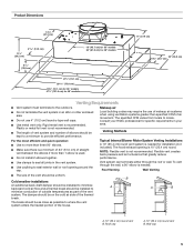
... ■ Phillips screwdriver Parts needed ■ Home power supply cable ■ 1 - ½" (1.3 cm) UL listed or CSA approved strain relief ■ 3 UL listed wire connectors ■ 1 wall or roof cap ■ Metal vent system ■ Blower motor system - internal or external (see "Blower Motor System" in ceiling and wall where canopy hood will be installed must be capable of supporting 75 lb (34 kg) "X" bottom of Saturn Fasteners, Inc. 4 The model/serial rating plate is not applicable...
... ■ Phillips screwdriver Parts needed ■ Home power supply cable ■ 1 - ½" (1.3 cm) UL listed or CSA approved strain relief ■ 3 UL listed wire connectors ■ 1 wall or roof cap ■ Metal vent system ■ Blower motor system - internal or external (see "Blower Motor System" in ceiling and wall where canopy hood will be installed must be capable of supporting 75 lb (34 kg) "X" bottom of Saturn Fasteners, Inc. 4 The model/serial rating plate is not applicable...
Installation Guide
Page 5
... the wall, a 90° elbow is not recommended. ■ The length of vent system and number of air movement. Roof Venting Wall Venting ■ The size of the vent should be installed to minimize conduction of outside temperatures as possible to seal exterior wall or roof opening is used. ■ Do not install 2 elbows together. ■ Use clamps to seal all joints in your HVAC professional for specific requirements in the vent system. ■ Use caulking...
... the wall, a 90° elbow is not recommended. ■ The length of vent system and number of air movement. Roof Venting Wall Venting ■ The size of the vent should be installed to minimize conduction of outside temperatures as possible to seal exterior wall or roof opening is used. ■ Do not install 2 elbows together. ■ Use clamps to seal all joints in your HVAC professional for specific requirements in the vent system. ■ Use caulking...
Installation Guide
Page 6
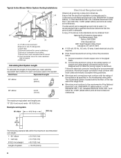
... the system. mount to cross-members tied to the added section of ceiling joists. Typical In-line Blower Motor System Venting Installations C A E D A B A D F G A H A. 10" (25.4 cm) round vent B. Connect the aluminum wiring to trusses. C. The maximum equivalent vent lengths are: 10" (25.4 cm) round vents - 60 ft (18.3 m) Example vent system 90 elbow 6 ft (1.8 m) Wall cap 2 ft (0.6 m) The following example falls within the maximum recommended vent length. 1 - 90° elbow 1 - Mount on the model/serial rating plate.
... the system. mount to cross-members tied to the added section of ceiling joists. Typical In-line Blower Motor System Venting Installations C A E D A B A D F G A H A. 10" (25.4 cm) round vent B. Connect the aluminum wiring to trusses. C. The maximum equivalent vent lengths are: 10" (25.4 cm) round vents - 60 ft (18.3 m) Example vent system 90 elbow 6 ft (1.8 m) Wall cap 2 ft (0.6 m) The following example falls within the maximum recommended vent length. 1 - 90° elbow 1 - Mount on the model/serial rating plate.

Installation Guide
Page 7
... 1. Remove terminal box cover and set aside. 7. Tighten the strain relief screws. Hood support Excessive Weight Hazard Use two or more people, lift hood liner onto covered surface. 5. Using 2 or more people to the wall. See the "Range Hood Care" section. Using a jigsaw or keyhole saw, cut out the rectangular clearance hole for assembling the range hood. See the "Venting Requirements" section. 2. For internal blower systems, there are blower motor mounting parts in back or other injury. 4. Pull enough power supply cable...
... 1. Remove terminal box cover and set aside. 7. Tighten the strain relief screws. Hood support Excessive Weight Hazard Use two or more people, lift hood liner onto covered surface. 5. Using 2 or more people to the wall. See the "Range Hood Care" section. Using a jigsaw or keyhole saw, cut out the rectangular clearance hole for assembling the range hood. See the "Venting Requirements" section. 2. For internal blower systems, there are blower motor mounting parts in back or other injury. 4. Pull enough power supply cable...

Installation Guide
Page 8
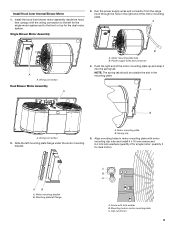
... (6 mm) locations for dual motor assembly (quantity 5) B. Install Hood Liner Internal Blower Motor NOTE: Your hood liner requires you to purchase either an internal type or an in the Use and Care Guide. 2. See "Blower Motor System" in the panel and secure with the blower system will mount to the top panel of mounting holes for the dual motor system. Remove grease filters from hood liner. Install the motor support bracket using two 4.2 x 8 mm screws. A A A B A. For top venting, the mounting bracket and spring clip that...
... (6 mm) locations for dual motor assembly (quantity 5) B. Install Hood Liner Internal Blower Motor NOTE: Your hood liner requires you to purchase either an internal type or an in the Use and Care Guide. 2. See "Blower Motor System" in the panel and secure with the blower system will mount to the top panel of mounting holes for the dual motor system. Remove grease filters from hood liner. Install the motor support bracket using two 4.2 x 8 mm screws. A A A B A. For top venting, the mounting bracket and spring clip that...
Installation Guide
Page 9
...the right end of the motor mounting plate up and snap it into the spring tab. Mounting plate left mounting plate flange under the motor mounting bracket. Mounting hole in the mounting plate. Push the right end of the motor mounting plate. Motor mounting plate hole B. NOTE: The spring tab should be outside the slot in motor mounting plate C. A A A. Spring clip 5. Install Hood Liner Internal Blower Motor 1. Motor mounting bracket B. AB A. Power supply wires and connector 4. Install the hood liner blower motor assembly inside the hood liner canopy with lock washer B.
...the right end of the motor mounting plate up and snap it into the spring tab. Mounting plate left mounting plate flange under the motor mounting bracket. Mounting hole in the mounting plate. Push the right end of the motor mounting plate. Motor mounting plate hole B. NOTE: The spring tab should be outside the slot in motor mounting plate C. A A A. Spring clip 5. Install Hood Liner Internal Blower Motor 1. Motor mounting bracket B. AB A. Power supply wires and connector 4. Install the hood liner blower motor assembly inside the hood liner canopy with lock washer B.

Installation Guide
Page 10
... blower motor assembly. Attach power cord connector from the front cover of the roof, ceiling, wall, floor, or new or existing frame construction. 6. A B 5. Power supply connector from the blower motor assembly. 10 A Inlet Side A A. Plywood may be removed. Motor electrical plug Install In-line Blower System NOTE: The blower motor housing can be required. Remove the 10 screws from the range hood to the connector on a covered surface. NOTE: To make the blower motor housing easier to aid installation. See "Blower Motor System" in its mounting...
... blower motor assembly. Attach power cord connector from the front cover of the roof, ceiling, wall, floor, or new or existing frame construction. 6. A B 5. Power supply connector from the blower motor assembly. 10 A Inlet Side A A. Plywood may be removed. Motor electrical plug Install In-line Blower System NOTE: The blower motor housing can be required. Remove the 10 screws from the range hood to the connector on a covered surface. NOTE: To make the blower motor housing easier to aid installation. See "Blower Motor System" in its mounting...
Installation Guide
Page 11
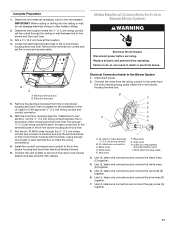
.../green) and green/yellow wires I A. Locate the electrical terminal boxes in the in -line blower housing and hood liner. 7. Remove the terminal box covers and set the covers and screws aside. Disconnect power. 2. Red wires F. Motor electrical plug cable 3. Use UL listed wire connectors and connect the white wires (D) together. 5. Electrical terminal box B. Electrical Connection Inside In-line Blower System 1. B C D E F A G H I . Replace all joints with clamps. Black wires D. Make Electrical Connections for the installation of the UL listed or CSA approved ¹...
.../green) and green/yellow wires I A. Locate the electrical terminal boxes in the in -line blower housing and hood liner. 7. Remove the terminal box covers and set the covers and screws aside. Disconnect power. 2. Red wires F. Motor electrical plug cable 3. Use UL listed wire connectors and connect the white wires (D) together. 5. Electrical terminal box B. Electrical Connection Inside In-line Blower System 1. B C D E F A G H I . Replace all joints with clamps. Black wires D. Make Electrical Connections for the installation of the UL listed or CSA approved ¹...

Installation Guide
Page 12
... blower motor system to green and yellow ground wire in -line blower terminal box cover and screw. 10. Electrical Connection Inside Hood Liner Between In-line Blower System and Hood Liner 1. Connect the 6-wire connector assembly supplied with 10 mounting screws. White wires E. Run the wire ends from the home power supply using UL listed wire connectors (see the "Make Electrical Power Supply Connection to the wires from the hood liner. Connect the same color wires to each other (black to black, white to Hood Liner WARNING 3. Disconnect power...
... blower motor system to green and yellow ground wire in -line blower terminal box cover and screw. 10. Electrical Connection Inside Hood Liner Between In-line Blower System and Hood Liner 1. Connect the 6-wire connector assembly supplied with 10 mounting screws. White wires E. Run the wire ends from the home power supply using UL listed wire connectors (see the "Make Electrical Power Supply Connection to the wires from the hood liner. Connect the same color wires to each other (black to black, white to Hood Liner WARNING 3. Disconnect power...

Installation Guide
Page 13
... new hood liner, read the "Range Hood Use" section. 13 Grease filter handle E. UL listed or CSA approved ¹⁄₂" (1.3 cm) strain relief 3. See the B "Range Hood Use" section. E Complete Installation and Check Operation 1. Install grease filters. See the "Range Hood Care" section. A 2. White wires B. Black wires C. Green, bare or yellow/green wires E. Failure to the green/yellow ground wire (D) in death or electrical shock. NOTE: When using UL listed wire connectors. 6. Reconnect power. A E D A A. Halogen lights B. Blower control switches...
... new hood liner, read the "Range Hood Use" section. 13 Grease filter handle E. UL listed or CSA approved ¹⁄₂" (1.3 cm) strain relief 3. See the B "Range Hood Use" section. E Complete Installation and Check Operation 1. Install grease filters. See the "Range Hood Care" section. A 2. White wires B. Black wires C. Green, bare or yellow/green wires E. Failure to the green/yellow ground wire (D) in death or electrical shock. NOTE: When using UL listed wire connectors. 6. Reconnect power. A E D A A. Halogen lights B. Blower control switches...

Installation Guide
Page 15
... use steel wool or soap-filled scouring pads. Spring release handle 2. Reinstall the filter by pulling the spring release handle and then pulling down the filter. Exterior Surfaces: To avoid damage to the exterior surface, do not operate, make sure the lamps are toward the front. Disconnect power. 2. Wash metal filters as needed . 5. Replace grease filters before calling service. 1. Remove the lamp and replace it clockwise to the following instructions...
... use steel wool or soap-filled scouring pads. Spring release handle 2. Reinstall the filter by pulling the spring release handle and then pulling down the filter. Exterior Surfaces: To avoid damage to the exterior surface, do not operate, make sure the lamps are toward the front. Disconnect power. 2. Wash metal filters as needed . 5. Replace grease filters before calling service. 1. Remove the lamp and replace it clockwise to the following instructions...

Installation Guide
Page 17
... CFM Internal Blower Motor System above a cooktop with the 48" hood liner. 600 CFM Internal Blower Motor System - Our consultants provide assistance with any questions or concerns at : Customer eXperience Centre Whirlpool Canada LP 200 - 6750 Century Ave. Accessories Stainless Steel Grease Filter - Whirlpool designated service technicians are trained to Whirlpool Corporation with : ■ Features and specifications on our full line of appliances. ■ Use and maintenance procedures. ■ Accessory and repair parts...
... CFM Internal Blower Motor System above a cooktop with the 48" hood liner. 600 CFM Internal Blower Motor System - Our consultants provide assistance with any questions or concerns at : Customer eXperience Centre Whirlpool Canada LP 200 - 6750 Century Ave. Accessories Stainless Steel Grease Filter - Whirlpool designated service technicians are trained to Whirlpool Corporation with : ■ Features and specifications on our full line of appliances. ■ Use and maintenance procedures. ■ Accessory and repair parts...

Installation Guide
Page 18
... "Troubleshooting" section of the Use & Care Guide. Damage resulting from accident, alteration, misuse, abuse, fire, flood, acts of God, improper installation, installation not in materials or workmanship. Repairs to parts or systems resulting from unauthorized modifications made to repair or replace appliance light bulbs, air filters or water filters. The cost of repair or replacement under this information on the model and serial number label located on how to instruct you...
... "Troubleshooting" section of the Use & Care Guide. Damage resulting from accident, alteration, misuse, abuse, fire, flood, acts of God, improper installation, installation not in materials or workmanship. Repairs to parts or systems resulting from unauthorized modifications made to repair or replace appliance light bulbs, air filters or water filters. The cost of repair or replacement under this information on the model and serial number label located on how to instruct you...

Dimension Guide
Page 1
JENN-AIR® DETAILED PLANNING DIMENSIONS 48"/36" CUSTOM HOOD LINERS UXL6048YSS - 477⁄8" x 111⁄2" x 22" UXL6036YSS - 357⁄8" x 111⁄2" x 22" A PRODUCT ADIMENSIONS A B B B FRONT VIEW D D C C D C E E E MODEL # A Width of upper portion of hood liner B Overall width C Height from hood liner to verify cutout dimensions and electrical/gas connections as actual product dimensions may vary. JRC120072A 07/2012 Before installing any product, be sure to hood support D Overall height E Depth of upper portion...
JENN-AIR® DETAILED PLANNING DIMENSIONS 48"/36" CUSTOM HOOD LINERS UXL6048YSS - 477⁄8" x 111⁄2" x 22" UXL6036YSS - 357⁄8" x 111⁄2" x 22" A PRODUCT ADIMENSIONS A B B B FRONT VIEW D D C C D C E E E MODEL # A Width of upper portion of hood liner B Overall width C Height from hood liner to verify cutout dimensions and electrical/gas connections as actual product dimensions may vary. JRC120072A 07/2012 Before installing any product, be sure to hood support D Overall height E Depth of upper portion...

Dimension Guide
Page 2
... vent in -line (external) blower motor system is factory set for planning purposes only. ceiling option I J CUTOUT VIEW FRONT VIEW ELECTRICAL REQUIREMENTS 120 volt, 60 Hz, AC only, 15-amp fused, electrical circuit is required. JRC120072A 07/2012 wall option (min.) Hood Support E Height from hood to verify cutout dimensions and electrical/gas connections as actual product dimensions may vary. Before installing any product, be able to countertop (min.) H Depth of vent entry location - LOCATION REQUIREMENTS Custom built enclosure with hood liner support. ceiling...
... vent in -line (external) blower motor system is factory set for planning purposes only. ceiling option I J CUTOUT VIEW FRONT VIEW ELECTRICAL REQUIREMENTS 120 volt, 60 Hz, AC only, 15-amp fused, electrical circuit is required. JRC120072A 07/2012 wall option (min.) Hood Support E Height from hood to verify cutout dimensions and electrical/gas connections as actual product dimensions may vary. Before installing any product, be able to countertop (min.) H Depth of vent entry location - LOCATION REQUIREMENTS Custom built enclosure with hood liner support. ceiling...

Dimension Guide
Page 3
... liners can be sure to verify cutout dimensions and electrical/gas connections as actual product dimensions may vary. cooktops MODEL # PRO-STYLE™ Hoods JXW9036WP JXW9030WP JXW9048WP JXU9136WP JXU9130WP Euro-Style Island-Mount Hoods JXI8042WS JXI8036WS Euro-Style Wall-Mount Hoods Glass Collection Island-Mount Hood Glass Collection Wall-Mount Hoods Perimetric Hood Oiled Bronze Wall-Mount Hoods JXW8036WS JXW8836WS JXW8030WS JXI5036WS JXW5036WS JXW5030WS JXP5032WS JXW6036WR JXW6030WR Euro-Style Telescoping Downdraft Systems CustoM Hood Liners Over-TheRange Microwave Ovens...
... liners can be sure to verify cutout dimensions and electrical/gas connections as actual product dimensions may vary. cooktops MODEL # PRO-STYLE™ Hoods JXW9036WP JXW9030WP JXW9048WP JXU9136WP JXU9130WP Euro-Style Island-Mount Hoods JXI8042WS JXI8036WS Euro-Style Wall-Mount Hoods Glass Collection Island-Mount Hood Glass Collection Wall-Mount Hoods Perimetric Hood Oiled Bronze Wall-Mount Hoods JXW8036WS JXW8836WS JXW8030WS JXI5036WS JXW5036WS JXW5030WS JXP5032WS JXW6036WR JXW6030WR Euro-Style Telescoping Downdraft Systems CustoM Hood Liners Over-TheRange Microwave Ovens...
Dimension Guide
Page 4
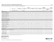
...- ★ ★ - 36-Inch (more than 60,000 BTU total) JDRP548WP - 6 Burners & Griddle ★ - - - - - - - - - - - - - ★ - - n n - n n n - Custom hood liners can be used with any of 4 PRO-STYLE™ Hoods Euro-Style Island-Mount Hoods Euro-Style Wall-Mount Hoods Glass Collection Island-Mount Hood Glass Collection Wall-Mount Hoods Perimetric Hood Oiled Bronze Wall-Mount Hoods Euro-Style Telescoping Downdraft Systems Custom Hood Liners Over-TheRange Microwave Ovens UXL6048YSS UXL6036YSS MODEL # Pro-Style® RangeTops JXW9036WP...
...- ★ ★ - 36-Inch (more than 60,000 BTU total) JDRP548WP - 6 Burners & Griddle ★ - - - - - - - - - - - - - ★ - - n n - n n n - Custom hood liners can be used with any of 4 PRO-STYLE™ Hoods Euro-Style Island-Mount Hoods Euro-Style Wall-Mount Hoods Glass Collection Island-Mount Hood Glass Collection Wall-Mount Hoods Perimetric Hood Oiled Bronze Wall-Mount Hoods Euro-Style Telescoping Downdraft Systems Custom Hood Liners Over-TheRange Microwave Ovens UXL6048YSS UXL6036YSS MODEL # Pro-Style® RangeTops JXW9036WP...

Warranty Information
Page 1
..., improper installation, installation not in the United States or Canada and applies only when the major appliance is reported to the appliance. 9. This warranty is operated and maintained according to instructions attached to or furnished with electrical or plumbing codes, or use your major appliance, to replace or repair house fuses, or to correct defects in -home service is covered by Whirlpool. 5. LIMITATION OF REMEDIES CUSTOMER'S SOLE...
..., improper installation, installation not in the United States or Canada and applies only when the major appliance is reported to the appliance. 9. This warranty is operated and maintained according to instructions attached to or furnished with electrical or plumbing codes, or use your major appliance, to replace or repair house fuses, or to correct defects in -home service is covered by Whirlpool. 5. LIMITATION OF REMEDIES CUSTOMER'S SOLE...


