Service Manual
Page 2
... Kodak's negligence or other fault. Auto Focus Models 19 Replacing the LENS MOUNT ASSEMBLY - Auto Focus Models 21 Installing the FOCUS SHAFT ASSEMBLY 23 Replacing the FOCUS SHAFT ASSEMBLY - Non Auto-Focus Models 23 Installing the FOCUS SHAFT ASSEMBLY 24 Adjustments 25 Adjusting the CYCLE SOLENOID 25 Adjusting the INDEXER LEVER ASSEMBLY 26 Adjusting the SLIDE LIFT LEVER MANUAL, with MECHANISM Out 27 Adjusting the SLIDE LIFT LEVER POWER with respect to prevent damage during all service...
... Kodak's negligence or other fault. Auto Focus Models 19 Replacing the LENS MOUNT ASSEMBLY - Auto Focus Models 21 Installing the FOCUS SHAFT ASSEMBLY 23 Replacing the FOCUS SHAFT ASSEMBLY - Non Auto-Focus Models 23 Installing the FOCUS SHAFT ASSEMBLY 24 Adjustments 25 Adjusting the CYCLE SOLENOID 25 Adjusting the INDEXER LEVER ASSEMBLY 26 Adjusting the SLIDE LIFT LEVER MANUAL, with MECHANISM Out 27 Adjusting the SLIDE LIFT LEVER POWER with respect to prevent damage during all service...
Service Manual
Page 4
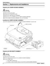
... COVER wires • 2 on SMALL CIRCUIT BOARD between the MOTOR and MECHANISM ASSEMBLY 4 18NOV97 - SCREW (6) LOWER HOUSING A100_0030HCA A100_0030HA Replacing the FAN SHAFT ASSEMBLY LAMP MODULE Warning Dangerous Voltage [1] Disconnect the main power. [2] Do the replacement procedure for the LOWER HOUSING ASSEMBLY in reverse order. SERVICE MANUAL Section 1: Replacements and Installations Replacing the LOWER HOUSING ASSEMBLY Warning Dangerous Voltage [1] Disconnect the main power. [2] Remove the PROJECTION LENS. [3] Remove the LAMP...
... COVER wires • 2 on SMALL CIRCUIT BOARD between the MOTOR and MECHANISM ASSEMBLY 4 18NOV97 - SCREW (6) LOWER HOUSING A100_0030HCA A100_0030HA Replacing the FAN SHAFT ASSEMBLY LAMP MODULE Warning Dangerous Voltage [1] Disconnect the main power. [2] Do the replacement procedure for the LOWER HOUSING ASSEMBLY in reverse order. SERVICE MANUAL Section 1: Replacements and Installations Replacing the LOWER HOUSING ASSEMBLY Warning Dangerous Voltage [1] Disconnect the main power. [2] Remove the PROJECTION LENS. [3] Remove the LAMP...

Service Manual
Page 5
... the TAB on the BLOWER COVER ASSEMBLY. Use SPRING HOOK TL-1165. Do not cause damage to the MOTOR wires. [15] Remove the RETAINER CLIP from the FAN SHAFT. [16] Pull the FAN up and off the FAN SHAFT to allow access to the MOTOR. SM5440-1 - 18NOV97 5 wires are still connected to the parts; SCREWS from the FAN SHAFT ASSEMBLY.
... the TAB on the BLOWER COVER ASSEMBLY. Use SPRING HOOK TL-1165. Do not cause damage to the MOTOR wires. [15] Remove the RETAINER CLIP from the FAN SHAFT. [16] Pull the FAN up and off the FAN SHAFT to allow access to the MOTOR. SM5440-1 - 18NOV97 5 wires are still connected to the parts; SCREWS from the FAN SHAFT ASSEMBLY.
Service Manual
Page 10
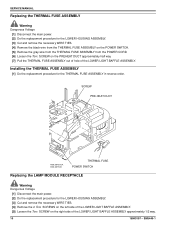
... 18NOV97 - SM5440-1 SERVICE MANUAL Replacing the THERMAL FUSE ASSEMBLY Warning Dangerous Voltage [1] Disconnect the main power. [2] Do the replacement procedure for the LOWER HOUSING ASSEMBLY. [3] Cut and remove the necessary WIRE TIES. [4] Remove the black wire from the THERMAL FUSE ASSEMBLY on the POWER SWITCH. [5] Remove the gray wire from the THERMAL FUSE ASSEMBLY from the POWER CORD. [6] Loosen the Torx SCREW on the...
... 18NOV97 - SM5440-1 SERVICE MANUAL Replacing the THERMAL FUSE ASSEMBLY Warning Dangerous Voltage [1] Disconnect the main power. [2] Do the replacement procedure for the LOWER HOUSING ASSEMBLY. [3] Cut and remove the necessary WIRE TIES. [4] Remove the black wire from the THERMAL FUSE ASSEMBLY on the POWER SWITCH. [5] Remove the gray wire from the THERMAL FUSE ASSEMBLY from the POWER CORD. [6] Loosen the Torx SCREW on the...

Service Manual
Page 13
... hole in reverse order. A091_4047CCA A091_4047CA Installing the MECHANISM ASSEMBLY Caution There might cause damage to the MECHANISM ASSEMBLY: • 1 yellow wire from CYCLE SWITCH • 1 orange wire from WIRE NUT • 1 green wire from POWER CORD • 2 green ground wires from the lower MECHANISM ASSEMBLY [7] Remove the FOCUS KNOB from the FRONT PANEL. [8] Remove the 3 Torx SCREWS from the MECHANISM ASSEMBLY. [12...
... hole in reverse order. A091_4047CCA A091_4047CA Installing the MECHANISM ASSEMBLY Caution There might cause damage to the MECHANISM ASSEMBLY: • 1 yellow wire from CYCLE SWITCH • 1 orange wire from WIRE NUT • 1 green wire from POWER CORD • 2 green ground wires from the lower MECHANISM ASSEMBLY [7] Remove the FOCUS KNOB from the FRONT PANEL. [8] Remove the 3 Torx SCREWS from the MECHANISM ASSEMBLY. [12...
Service Manual
Page 18
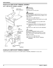
... set the parts on a clean cloth. Caution Remove the CONDENSER LENS and HEAT ABSORBING GLASS and set on the bottom side of the LAMP MODULE next to the parts. [7] Remove the LAMP EJECTOR. [8] Remove the LAMP SOCKET TERMINAL ASSEMBLY. SERVICE MANUAL Replacing the LAMP SOCKET TERMINAL ASSEMBLY Style 1 LAMP SOCKET TERMINAL ASSEMBLY SCREW LAMP DOOR PLATE ASSEMBLY Warning Dangerous Voltage [1] Disconnect the main power. TAB (2) CONDENSER LENS HEAT ABSORBING GLASS A091_0018CCA A091_0018CA Installing...
... set the parts on a clean cloth. Caution Remove the CONDENSER LENS and HEAT ABSORBING GLASS and set on the bottom side of the LAMP MODULE next to the parts. [7] Remove the LAMP EJECTOR. [8] Remove the LAMP SOCKET TERMINAL ASSEMBLY. SERVICE MANUAL Replacing the LAMP SOCKET TERMINAL ASSEMBLY Style 1 LAMP SOCKET TERMINAL ASSEMBLY SCREW LAMP DOOR PLATE ASSEMBLY Warning Dangerous Voltage [1] Disconnect the main power. TAB (2) CONDENSER LENS HEAT ABSORBING GLASS A091_0018CCA A091_0018CA Installing...

Service Manual
Page 19
... Installing the LENS MOUNT ASSEMBLY - Auto Focus Models [1] Do the replacement procedure for the LOWER HOUSING ASSEMBLY. [3] Remove the FOCUS KNOB. Important It is necessary to push the AUTO-FOCUS BRACKET backward and forward to allow access to the SCREWS on the LENS MOUNT ASSEMBLY. [4] Remove the 3 SCREWS from the LENS MOUNT ASSEMBLY. [5] Lift and remove the LENS MOUNT ASSEMBLY. Auto Focus Model LENS MOUNT ASSEMBLY SCREW (3) Warning Dangerous Voltage [1] Disconnect the main power. [2] Do the replacement procedure for the LENS MOUNT...
... Installing the LENS MOUNT ASSEMBLY - Auto Focus Models [1] Do the replacement procedure for the LOWER HOUSING ASSEMBLY. [3] Remove the FOCUS KNOB. Important It is necessary to push the AUTO-FOCUS BRACKET backward and forward to allow access to the SCREWS on the LENS MOUNT ASSEMBLY. [4] Remove the 3 SCREWS from the LENS MOUNT ASSEMBLY. [5] Lift and remove the LENS MOUNT ASSEMBLY. Auto Focus Model LENS MOUNT ASSEMBLY SCREW (3) Warning Dangerous Voltage [1] Disconnect the main power. [2] Do the replacement procedure for the LENS MOUNT...
Service Manual
Page 20
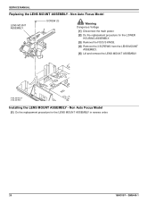
SM5440-1 Non Auto Focus Model [1] Do the replacement procedure for the LOWER HOUSING ASSEMBLY. [3] Remove the FOCUS KNOB. [4] Remove the 3 SCREWS from the LENS MOUNT ASSEMBLY. [5] Lift and remove the LENS MOUNT ASSEMBLY. SERVICE MANUAL Replacing the LENS MOUNT ASSEMBLY - Non Auto Focus Model LENS MOUNT ASSEMBLY SCREW (3) Warning Dangerous Voltage [1] Disconnect the main power. [2] Do the replacement procedure for the LENS MOUNT ASSEMBLY in reverse order. 20 18NOV97 - A100_0019GCA A100_0019GA Installing the LENS MOUNT ASSEMBLY -
SM5440-1 Non Auto Focus Model [1] Do the replacement procedure for the LOWER HOUSING ASSEMBLY. [3] Remove the FOCUS KNOB. [4] Remove the 3 SCREWS from the LENS MOUNT ASSEMBLY. [5] Lift and remove the LENS MOUNT ASSEMBLY. SERVICE MANUAL Replacing the LENS MOUNT ASSEMBLY - Non Auto Focus Model LENS MOUNT ASSEMBLY SCREW (3) Warning Dangerous Voltage [1] Disconnect the main power. [2] Do the replacement procedure for the LENS MOUNT ASSEMBLY in reverse order. 20 18NOV97 - A100_0019GCA A100_0019GA Installing the LENS MOUNT ASSEMBLY -

Service Manual
Page 21
... Keep the AUTO-FOCUS SWITCH LEVER that the end of the AUTO-FOCUS LEVER engages with the hole in reverse order. Installing the AUTO-FOCUS SWITCH ASSEMBLY Important Align the 2 TABS on the LENS MOUNT ASSEMBLY. [5] Remove the 3 SCREWS from the LENS MOUNT ASSEMBLY. [6] Lift and remove the LENS MOUNT ASSEMBLY. [7] Remove the gray, red, and black wires from the AUTO- Auto Focus Models Warning Dangerous Voltage [1] Disconnect the main power. Replacing the AUTO-FOCUS SWITCH ASSEMBLY Replacements and Installations AUTO FOCUS MOTOR BRACKET Warning Dangerous...
... Keep the AUTO-FOCUS SWITCH LEVER that the end of the AUTO-FOCUS LEVER engages with the hole in reverse order. Installing the AUTO-FOCUS SWITCH ASSEMBLY Important Align the 2 TABS on the LENS MOUNT ASSEMBLY. [5] Remove the 3 SCREWS from the LENS MOUNT ASSEMBLY. [6] Lift and remove the LENS MOUNT ASSEMBLY. [7] Remove the gray, red, and black wires from the AUTO- Auto Focus Models Warning Dangerous Voltage [1] Disconnect the main power. Replacing the AUTO-FOCUS SWITCH ASSEMBLY Replacements and Installations AUTO FOCUS MOTOR BRACKET Warning Dangerous...
Service Manual
Page 22
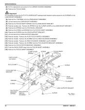
... LENS MOUNT ASSEMBLY. [5] Lift and remove the LENS MOUNT ASSEMBLY. [6] Remove the FOCUS SHAFT SPRING from the LENS MOUNT BRACKET. [7] Remote models only: Remove the SPRING from the CLAMP LEVER on the LENS MOUNT BRACKET. [8] Remove the SPRING from the PHOTOCELL BRACKET. [9] Remove the E-RING and SPACER from the FOCUS SHAFT ASSEMBLY. [10] Remove the SCREW from the LENS SUPPORT BRACKET. [11] Lift and remove the LENS SUPPORT BRACKET. [12] Remote models: Remove the AUTO-FOCUS SWITCH ASSEMBLY. [13] Remote models: Remove the SCREW...
... LENS MOUNT ASSEMBLY. [5] Lift and remove the LENS MOUNT ASSEMBLY. [6] Remove the FOCUS SHAFT SPRING from the LENS MOUNT BRACKET. [7] Remote models only: Remove the SPRING from the CLAMP LEVER on the LENS MOUNT BRACKET. [8] Remove the SPRING from the PHOTOCELL BRACKET. [9] Remove the E-RING and SPACER from the FOCUS SHAFT ASSEMBLY. [10] Remove the SCREW from the LENS SUPPORT BRACKET. [11] Lift and remove the LENS SUPPORT BRACKET. [12] Remote models: Remove the AUTO-FOCUS SWITCH ASSEMBLY. [13] Remote models: Remove the SCREW...

Service Manual
Page 23
... SCREW from the FOCUS MOTOR BRACKET ASSEMBLY. [12] Remove the FOCUS MOTOR BRACKET ASSEMBLY. [13] Remove the FOCUS SHAFT ASSEMBLY. Replacing the FOCUS SHAFT ASSEMBLY - SCREW FOCUS SHAFT ASSEMBLY FOCUS SHAFT SPRING FOCUS MOTOR BRACKET SPACER E-RING SM5440-1 - 18NOV97 LENS SUPPORT BRACKET SCREW A091_0020HCA A091_0020HA 23 See the Adjustments section. Non Auto-Focus Models Warning Dangerous Voltage [1] Disconnect the main power. [2] Do the replacement procedure for the PHOTOCELL NULL and AUTO-FOCUS CLAMP after installation...
... SCREW from the FOCUS MOTOR BRACKET ASSEMBLY. [12] Remove the FOCUS MOTOR BRACKET ASSEMBLY. [13] Remove the FOCUS SHAFT ASSEMBLY. Replacing the FOCUS SHAFT ASSEMBLY - SCREW FOCUS SHAFT ASSEMBLY FOCUS SHAFT SPRING FOCUS MOTOR BRACKET SPACER E-RING SM5440-1 - 18NOV97 LENS SUPPORT BRACKET SCREW A091_0020HCA A091_0020HA 23 See the Adjustments section. Non Auto-Focus Models Warning Dangerous Voltage [1] Disconnect the main power. [2] Do the replacement procedure for the PHOTOCELL NULL and AUTO-FOCUS CLAMP after installation...
Service Manual
Page 28
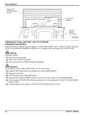
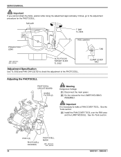
... target of the image on the GATE MECHANISM. Warning Dangerous Voltage [1] Disconnect the main power. [2] Remove the PROJECTION LENS. [3] Do the removal for the LOWER HOUSING ASSEMBLY. Use TL-3005 or TL-1165 to make a FAN COVER TOOL. See the Tools section. [4] Install the FAN COVER TOOL over the FAN area and the LAMP MODULE. [5] Energize the projector. [6] Set the projector to the LOW LAMP position. [7] Install the AUTO-FOCUS TARGET SLIDE...
... target of the image on the GATE MECHANISM. Warning Dangerous Voltage [1] Disconnect the main power. [2] Remove the PROJECTION LENS. [3] Do the removal for the LOWER HOUSING ASSEMBLY. Use TL-3005 or TL-1165 to make a FAN COVER TOOL. See the Tools section. [4] Install the FAN COVER TOOL over the FAN area and the LAMP MODULE. [5] Energize the projector. [6] Set the projector to the LOW LAMP position. [7] Install the AUTO-FOCUS TARGET SLIDE...

Service Manual
Page 29
.... [4] Energize the projector. [5] Set the projector to the LO-LAMP position. [6] Install and hold the AUTO FOCUS TARGET SLIDE TL-3002 until the image is in the NULL position. If the TAB is fully seated in the GATE MECHANISM. [7] Look through the PROJECTION LENS hole and observe the focus light path on the TARGET SLIDE. SM5440-1 - 18NOV97 29 Adjusting the NULL Warning Dangerous Voltage...
.... [4] Energize the projector. [5] Set the projector to the LO-LAMP position. [6] Install and hold the AUTO FOCUS TARGET SLIDE TL-3002 until the image is in the NULL position. If the TAB is fully seated in the GATE MECHANISM. [7] Look through the PROJECTION LENS hole and observe the focus light path on the TARGET SLIDE. SM5440-1 - 18NOV97 29 Adjusting the NULL Warning Dangerous Voltage...
Service Manual
Page 30
... FAN COVER TOOL over the FAN area and the LAMP MODULE. See the Tools section. SERVICE MANUAL Important If you cannot obtain the NULL position after doing the adjustment approximately 3 times, go to the adjustment procedure for the LOWER HOUSING ASSEMBLY. POST (2) PHOTOCELL HOUSING PHOTOCELL MASK A091_4032GCA A091_4032GA 30 18NOV97 - light path T-BAR TL-3003 PROJECTION LENS NULL position TAB A091_4031BCA A091_4031BA AUTO-FOCUS...
... FAN COVER TOOL over the FAN area and the LAMP MODULE. See the Tools section. SERVICE MANUAL Important If you cannot obtain the NULL position after doing the adjustment approximately 3 times, go to the adjustment procedure for the LOWER HOUSING ASSEMBLY. POST (2) PHOTOCELL HOUSING PHOTOCELL MASK A091_4032GCA A091_4032GA 30 18NOV97 - light path T-BAR TL-3003 PROJECTION LENS NULL position TAB A091_4031BCA A091_4031BA AUTO-FOCUS...

Service Manual
Page 31
... bend enough to the LO-LAMP position. [6] Install and hold the AUTO FOCUS TARGET SLIDE TL-3002 until it is correct. Use a SOLDERING IRON. [10] Remove the 2 Wratten FILTERS and the PHOTOCELL MASK. Warning Dangerous Voltage [8] Disconnect the main power. [9] Heat the 2 POSTS on the AUTO-FOCUS TARGET SLIDE TL-3002. Adjustments Warning Dangerous Voltage [4] Energize the projector. [5] Set the projector to pull the PHOTOCELL CIRCUIT...
... bend enough to the LO-LAMP position. [6] Install and hold the AUTO FOCUS TARGET SLIDE TL-3002 until it is correct. Use a SOLDERING IRON. [10] Remove the 2 Wratten FILTERS and the PHOTOCELL MASK. Warning Dangerous Voltage [8] Disconnect the main power. [9] Heat the 2 POSTS on the AUTO-FOCUS TARGET SLIDE TL-3002. Adjustments Warning Dangerous Voltage [4] Energize the projector. [5] Set the projector to pull the PHOTOCELL CIRCUIT...

Service Manual
Page 34
.... SM5440-1 SERVICE MANUAL Adjusting the CLAMP PAD ASSEMBLY SCREW NUT CLAMP PAD ASSEMBLY A091_4041GCA A091_4041GA Warning Dangerous Voltage [1] Disconnect the main power. [2] Do the removal for the LOWER HOUSING. [2] Insert a thin SLIDE into the GATE MECHANISM; See the Tools section. [4] Connect the REMOTE CONTROL ASSEMBLY EC-3 to make a FAN COVER TOOL. Adjustment Specification The PRESSURE PAD should move . [9] Release the REMOTE FOCUS. [10...
.... SM5440-1 SERVICE MANUAL Adjusting the CLAMP PAD ASSEMBLY SCREW NUT CLAMP PAD ASSEMBLY A091_4041GCA A091_4041GA Warning Dangerous Voltage [1] Disconnect the main power. [2] Do the removal for the LOWER HOUSING. [2] Insert a thin SLIDE into the GATE MECHANISM; See the Tools section. [4] Connect the REMOTE CONTROL ASSEMBLY EC-3 to make a FAN COVER TOOL. Adjustment Specification The PRESSURE PAD should move . [9] Release the REMOTE FOCUS. [10...

Service Manual
Page 40
... 82 V, 300 W, 35 hours average life • EXW 82 V, 300 W, 15 hours average lamp life • FHS 82 V, 300 W, 70 hours average life • EXY 82 V, 300 W, 200 hours average life • On Long Life models, the LAMP voltage is 2.5 mA. 18NOV97 - SERVICE MANUAL Section 5: Specifications Electrical Supply Item Power Consumption Dimensions Slide size Slide change time LAMP and voltages Lumen Output Operating temperature Cooling Approvals Environmental storage Environmental operation Safety Dielectric strength 40...
... 82 V, 300 W, 35 hours average life • EXW 82 V, 300 W, 15 hours average lamp life • FHS 82 V, 300 W, 70 hours average life • EXY 82 V, 300 W, 200 hours average life • On Long Life models, the LAMP voltage is 2.5 mA. 18NOV97 - SERVICE MANUAL Section 5: Specifications Electrical Supply Item Power Consumption Dimensions Slide size Slide change time LAMP and voltages Lumen Output Operating temperature Cooling Approvals Environmental storage Environmental operation Safety Dielectric strength 40...

Service Manual
Page 41
..., LAMP CONTROL • PIN 7 - Automatic Timer Item Elevation Auto Focus System Reliability Maintenance Warranty 7-PIN REMOTE CONTROL (See illustration on next page.) REMOTE INLET Desription Operates between failures) of operation, or after the slide is recommended every 1500 hours of 7500 operation hours. Green, FORWARD TRAY CYCLE • PIN 3 - Preventive maintenance by more than 3 times the focus and reverse specifications. Orange, REVERSE TRAY CYCLE • PIN 4 - Yellow, COMMON • PIN 6 - White, LAMP CONTROL Specifications...
..., LAMP CONTROL • PIN 7 - Automatic Timer Item Elevation Auto Focus System Reliability Maintenance Warranty 7-PIN REMOTE CONTROL (See illustration on next page.) REMOTE INLET Desription Operates between failures) of operation, or after the slide is recommended every 1500 hours of 7500 operation hours. Green, FORWARD TRAY CYCLE • PIN 3 - Preventive maintenance by more than 3 times the focus and reverse specifications. Orange, REVERSE TRAY CYCLE • PIN 4 - Yellow, COMMON • PIN 6 - White, LAMP CONTROL Specifications...
Service Manual
Page 48
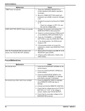
.... 1. Check for damage and install a new part if necessary. 1. Malfunction No manual focus No remote focus (Non Auto Focus models) Check 1. Check the REMOTE CORD for the correct tension. 2. Actuate and hold the REMOTE CONTROL. 3. SM5440-1 SERVICE MANUAL Malfunction TIMER does not operate DARK SHUTTER SWITCH does not operate After the FOCUS MOTOR energizes and moves, the FOCUS MOTOR oscillates. Check the LENS SUPPORT SPRING for correct operation and install a new part if necessary. 2. Check the VARIABLE RESISTOR for correct tension. 3. Energize the projector...
.... 1. Check for damage and install a new part if necessary. 1. Malfunction No manual focus No remote focus (Non Auto Focus models) Check 1. Check the REMOTE CORD for the correct tension. 2. Actuate and hold the REMOTE CONTROL. 3. SM5440-1 SERVICE MANUAL Malfunction TIMER does not operate DARK SHUTTER SWITCH does not operate After the FOCUS MOTOR energizes and moves, the FOCUS MOTOR oscillates. Check the LENS SUPPORT SPRING for correct operation and install a new part if necessary. 2. Check the VARIABLE RESISTOR for correct tension. 3. Energize the projector...

Service Manual
Page 50
....8 V ac. If the FOCUS MOTOR stops operating continually, install a new LAMP MODULE ASSEMBLY. 4. Do the adjustment for a light leak: • Install a different LAMP MODULE ASSEMBLY. AUTO FOCUS adjusts after REMOTE use Check 1. Check that the wires of the TARGET and NULL is 28 V ac. 5. Check the components on the AUTO FOCUS MOTOR. 1. The voltage from 1 to the mark on the CIRCUIT BOARD for damage. 1. the blue wire goes to 3 is...
....8 V ac. If the FOCUS MOTOR stops operating continually, install a new LAMP MODULE ASSEMBLY. 4. Do the adjustment for a light leak: • Install a different LAMP MODULE ASSEMBLY. AUTO FOCUS adjusts after REMOTE use Check 1. Check that the wires of the TARGET and NULL is 28 V ac. 5. Check the components on the AUTO FOCUS MOTOR. 1. The voltage from 1 to the mark on the CIRCUIT BOARD for damage. 1. the blue wire goes to 3 is...


