Service Manual
Page 1
{ServiceManual}{Production}{KodakServiceSupport} Publication No. SM5440-1 18NOV97 Supersedes SM5440-1 13MAY97 Kodak Home Page on Internet SERVICE MANUAL for the Kodak Carousel NEW LOOK PROJECTORS Standard and Long Life Models 4200, 4200-J, 4200-KK, 4400, 4600, 4600-KK, 5600, 5600-J, and 5600-KK Intranet Table of Contents © Eastman Kodak Company, 1999 A100_0029HA
{ServiceManual}{Production}{KodakServiceSupport} Publication No. SM5440-1 18NOV97 Supersedes SM5440-1 13MAY97 Kodak Home Page on Internet SERVICE MANUAL for the Kodak Carousel NEW LOOK PROJECTORS Standard and Long Life Models 4200, 4200-J, 4200-KK, 4400, 4600, 4600-KK, 5600, 5600-J, and 5600-KK Intranet Table of Contents © Eastman Kodak Company, 1999 A100_0029HA
Service Manual
Page 18
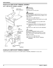
... - SERVICE MANUAL Replacing the LAMP SOCKET TERMINAL ASSEMBLY Style 1 LAMP SOCKET TERMINAL ASSEMBLY SCREW LAMP DOOR PLATE ASSEMBLY Warning Dangerous Voltage [1] Disconnect the main power. PROJECTOR LAMP LAMP EJECTOR LAMP SOCKET TERMINAL ASSEMBLY Important The EXTRA BRIGHT LAMP MODULE does not have a HEAT ABSORBING GLASS and has a LABEL on the LAMP...
... - SERVICE MANUAL Replacing the LAMP SOCKET TERMINAL ASSEMBLY Style 1 LAMP SOCKET TERMINAL ASSEMBLY SCREW LAMP DOOR PLATE ASSEMBLY Warning Dangerous Voltage [1] Disconnect the main power. PROJECTOR LAMP LAMP EJECTOR LAMP SOCKET TERMINAL ASSEMBLY Important The EXTRA BRIGHT LAMP MODULE does not have a HEAT ABSORBING GLASS and has a LABEL on the LAMP...

Service Manual
Page 25
... not have to be removed to check for the LOWER HOUSING ASSEMBLY. [3] Bend the CYCLE LEVER up or down. Use T-BAR TL-3003. [4] Energize the projector. [5] Press the "FORWARD" BUTTON to check for correct operation. [6] Press the "REVERSE" BUTTON to do this adjustment. [2] Do the removal for correct operation. [7] Do the...
... not have to be removed to check for the LOWER HOUSING ASSEMBLY. [3] Bend the CYCLE LEVER up or down. Use T-BAR TL-3003. [4] Energize the projector. [5] Press the "FORWARD" BUTTON to check for correct operation. [6] Press the "REVERSE" BUTTON to do this adjustment. [2] Do the removal for correct operation. [7] Do the...
Service Manual
Page 28
... path on the GATE MECHANISM. See the Tools section. [4] Install the FAN COVER TOOL over the FAN area and the LAMP MODULE. [5] Energize the projector. [6] Set the projector to make a FAN COVER TOOL. SERVICE MANUAL SLIDE LIFT LEVER GUAGE TL-3001 SLIDE LIFT LEVER SELECT LEVER (not shown) A091_0016BCA A091_0016BA Adjusting the...
... path on the GATE MECHANISM. See the Tools section. [4] Install the FAN COVER TOOL over the FAN area and the LAMP MODULE. [5] Energize the projector. [6] Set the projector to make a FAN COVER TOOL. SERVICE MANUAL SLIDE LIFT LEVER GUAGE TL-3001 SLIDE LIFT LEVER SELECT LEVER (not shown) A091_0016BCA A091_0016BA Adjusting the...

Service Manual
Page 29
... the image is within the target on the CLAMP PAD ASSEMBLY is in the NULL position. SM5440-1 - 18NOV97 29 See the Tools section. [4] Energize the projector. [5] Set the projector to make a FAN COVER TOOL.
... the image is within the target on the CLAMP PAD ASSEMBLY is in the NULL position. SM5440-1 - 18NOV97 29 See the Tools section. [4] Energize the projector. [5] Set the projector to make a FAN COVER TOOL.

Service Manual
Page 31
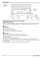
.... Warning Dangerous Voltage [8] Disconnect the main power. [9] Heat the 2 POSTS on the AUTO-FOCUS TARGET SLIDE TL-3002. Adjustments Warning Dangerous Voltage [4] Energize the projector. [5] Set the projector to pull the PHOTOCELL CIRCUIT BOARD up and off the PHOTOCELL HOUSING. If not, do the adjustment procedure for the FOCUS LIGHT PATH. SM5440...
.... Warning Dangerous Voltage [8] Disconnect the main power. [9] Heat the 2 POSTS on the AUTO-FOCUS TARGET SLIDE TL-3002. Adjustments Warning Dangerous Voltage [4] Energize the projector. [5] Set the projector to pull the PHOTOCELL CIRCUIT BOARD up and off the PHOTOCELL HOUSING. If not, do the adjustment procedure for the FOCUS LIGHT PATH. SM5440...

Service Manual
Page 33
...] Bend the CLAMP PAD ASSEMBLY until the image is in the center of the FAN CAP; A091_4030BCA A091_4030BA SM5440-1 - 18NOV97 33 Adjustments [16] Set the projector to check that the CLAMP PAD ASSEMBLY moves forward and backward. T-BAR TL-3003 hole FAN CAP light image AUTO-FOCUS TARGET SLIDE TL-3002...
...] Bend the CLAMP PAD ASSEMBLY until the image is in the center of the FAN CAP; A091_4030BCA A091_4030BA SM5440-1 - 18NOV97 33 Adjustments [16] Set the projector to check that the CLAMP PAD ASSEMBLY moves forward and backward. T-BAR TL-3003 hole FAN CAP light image AUTO-FOCUS TARGET SLIDE TL-3002...

Service Manual
Page 36
see the illustrations. • FAN • INDEXER LEVER and TOP PLATE • WORM PULLEY ASSEMBLY • CAM STACK ASSEMBLY • CYCLE LEVERS • PIVOT SHAFT and LEVERS • LENS MOUNT ASSEMBLY A091_4037GA 36 18NOV97 - SERVICE MANUAL Section 3: Lubrication Apply lubricant SUPER LUBE TL-4276 to the following parts and areas of the projector; SM5440-1
see the illustrations. • FAN • INDEXER LEVER and TOP PLATE • WORM PULLEY ASSEMBLY • CAM STACK ASSEMBLY • CYCLE LEVERS • PIVOT SHAFT and LEVERS • LENS MOUNT ASSEMBLY A091_4037GA 36 18NOV97 - SERVICE MANUAL Section 3: Lubrication Apply lubricant SUPER LUBE TL-4276 to the following parts and areas of the projector; SM5440-1

Service Manual
Page 39
Cut here. To operate the projector with the LOWER HOUSING removed, make a FAN COVER TOOL. Section 4: Tools Tools TL-1744 TL-2264 TL-3002 TL-3003 TL-3005 TL-3255 TL-4276 Tool Description AUTO-FOCUS GAUGE FOCUS TEST (flat field) AUTO-FOCUS TARGET SLIDE ADJUSTMENT T-BAR ADJUSTMENT TOOL Torx DRIVER SET SUPER LUBE DIGITAL MULTIMETER Tools The LOWER HOUSING ASSEMBLY is a part of the cooling function. FAN COVER TOOL 11.5 cm (4.5 in.) A091_0024GCA A091_0024GA SM5440-1 - 18NOV97 39
Cut here. To operate the projector with the LOWER HOUSING removed, make a FAN COVER TOOL. Section 4: Tools Tools TL-1744 TL-2264 TL-3002 TL-3003 TL-3005 TL-3255 TL-4276 Tool Description AUTO-FOCUS GAUGE FOCUS TEST (flat field) AUTO-FOCUS TARGET SLIDE ADJUSTMENT T-BAR ADJUSTMENT TOOL Torx DRIVER SET SUPER LUBE DIGITAL MULTIMETER Tools The LOWER HOUSING ASSEMBLY is a part of the cooling function. FAN COVER TOOL 11.5 cm (4.5 in.) A091_0024GCA A091_0024GA SM5440-1 - 18NOV97 39

Service Manual
Page 40
...% humidity in high • 21 - 27 C (70 - 80 F), 20 - 60% humidity optimum Fan speed is 2780 or 3000 RPMs, 1360 BTUs per hour to cool projector UL Complies with storage test specifications (TS 172) Complies with EXR lamp • EXTRA BRIGHT LAMP MODULE has a 30% increase in .) 1 second • EXR 82...
...% humidity in high • 21 - 27 C (70 - 80 F), 20 - 60% humidity optimum Fan speed is 2780 or 3000 RPMs, 1360 BTUs per hour to cool projector UL Complies with storage test specifications (TS 172) Complies with EXR lamp • EXTRA BRIGHT LAMP MODULE has a 30% increase in .) 1 second • EXR 82...

Service Manual
Page 41
... AC N 4 7W 7-PIN PLUG 5Y 82 V AC 2 3 6N G O 0 V AC Common 24 V AC Unloaded A100_0023ACA A100_0023AA SM5440-1 - 18NOV97 41 The projector has a MTBF (mean time between the following times: • Fast = 3 1 second • Slow = 22 6 seconds 14 maximum front elevation assembly. • After...2 - Brown, RACK SOLENOID • PIN 5 - See the owner's manual. • PIN 1 - Yellow, COMMON • PIN 6 - The projector can operate for the difference in the slide position from the focus and reverse specifications by a qualified service person is recommended every 1500 hours of...
... AC N 4 7W 7-PIN PLUG 5Y 82 V AC 2 3 6N G O 0 V AC Common 24 V AC Unloaded A100_0023ACA A100_0023AA SM5440-1 - 18NOV97 41 The projector has a MTBF (mean time between the following times: • Fast = 3 1 second • Slow = 22 6 seconds 14 maximum front elevation assembly. • After...2 - Brown, RACK SOLENOID • PIN 5 - See the owner's manual. • PIN 1 - Yellow, COMMON • PIN 6 - The projector can operate for the difference in the slide position from the focus and reverse specifications by a qualified service person is recommended every 1500 hours of...

Service Manual
Page 44
... COMPONENT BOARD ASSEMBLY 256809 Voltages WWK R A V V O B Y B J1 R3 CR2 CR3 CR4 Q1 Q2 R6 R4 R5 C5 R17 C4 R Y G N R WW J2 F1 R7 CR5 SLIDE PROJECTOR BOARD Q3 C1 CR1 R12 ++ R11 R10 C3 C2 R13 R14 CR6 R15 Q4 Description TIMER Circuit TIMER Circuit TIMER Circuit CYCLE HOLD DOWN REVERSE...
... COMPONENT BOARD ASSEMBLY 256809 Voltages WWK R A V V O B Y B J1 R3 CR2 CR3 CR4 Q1 Q2 R6 R4 R5 C5 R17 C4 R Y G N R WW J2 F1 R7 CR5 SLIDE PROJECTOR BOARD Q3 C1 CR1 R12 ++ R11 R10 C3 C2 R13 R14 CR6 R15 Q4 Description TIMER Circuit TIMER Circuit TIMER Circuit CYCLE HOLD DOWN REVERSE...

Service Manual
Page 46
...is a short•circuit causing the malfunction, the SOLENOID will not rotate. 4. Reverse does not operate, forward operates, voltages are correct. Projector has continual cycle. Install a new CAM STACK ASSEMBLY; See the adjustment for binds. Check for the following: • correct alignment of the... CYCLE LEVER (use SUPER LUBE TL-4276) 3. Check the DIRECTION LEVER for the CYCLE LEVER. 2. Projector does not complete a cycle; Check the CYCLE SOLENOID for the CYCLE SOLENOID. 2. Clean and lubricate the parts as necessary. SM5440-1 Forward...
...is a short•circuit causing the malfunction, the SOLENOID will not rotate. 4. Reverse does not operate, forward operates, voltages are correct. Projector has continual cycle. Install a new CAM STACK ASSEMBLY; See the adjustment for binds. Check for the following: • correct alignment of the... CYCLE LEVER (use SUPER LUBE TL-4276) 3. Check the DIRECTION LEVER for the CYCLE LEVER. 2. Projector does not complete a cycle; Check the CYCLE SOLENOID for the CYCLE SOLENOID. 2. Clean and lubricate the parts as necessary. SM5440-1 Forward...

Service Manual
Page 47
...is in the forward direction. • Check that the LOCATOR LEVER moves correctly and is parallel with the TOP HOUSING. Operate the projector in the correct alignment with the TOP HOUSING. Check that the DIRECTION LEVER LINK is on the DIRECTION LEVER. 3. Check that the... SPRING is in the DIRECTION LEVER ASSEMBLY. 4. SLIDE TRAY does not advance smoothly. Check 1. Malfunction The projector does not change cycles when using a DISSOLVE CONTROL; the REMOTE CONTROL and CONTROL PANEL BUTTONS operate correctly. Press and hold the SELECT BUTTON down...
...is in the forward direction. • Check that the LOCATOR LEVER moves correctly and is parallel with the TOP HOUSING. Operate the projector in the correct alignment with the TOP HOUSING. Check that the DIRECTION LEVER LINK is on the DIRECTION LEVER. 3. Check that the... SPRING is in the DIRECTION LEVER ASSEMBLY. 4. SLIDE TRAY does not advance smoothly. Check 1. Malfunction The projector does not change cycles when using a DISSOLVE CONTROL; the REMOTE CONTROL and CONTROL PANEL BUTTONS operate correctly. Press and hold the SELECT BUTTON down...
Service Manual
Page 48
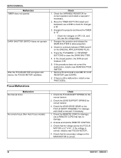
... does not operate DARK SHUTTER SWITCH does not operate After the FOCUS MOTOR energizes and moves, the FOCUS MOTOR oscillates. Energize the projector and release the DARK SHUTTER to "S". • Check the voltages on the FOCUS SHAFT ASSEMBLY for correct tension. 3. If there ... SHUTTER SWITCH. 1. Focus Malfunctions Check 1. Move the TIMER BUTTON forward and backward; use a REMOTE CORD that has no damage. 2. Energize the projector and move the TIMER to allow projection. 2. In the closed position, the DVM should measure 0 W. 5. Check that the voltage across the FOCUS...
... does not operate DARK SHUTTER SWITCH does not operate After the FOCUS MOTOR energizes and moves, the FOCUS MOTOR oscillates. Energize the projector and release the DARK SHUTTER to "S". • Check the voltages on the FOCUS SHAFT ASSEMBLY for correct tension. 3. If there ... SHUTTER SWITCH. 1. Focus Malfunctions Check 1. Move the TIMER BUTTON forward and backward; use a REMOTE CORD that has no damage. 2. Energize the projector and move the TIMER to allow projection. 2. In the closed position, the DVM should measure 0 W. 5. Check that the voltage across the FOCUS...