Service Manual
Page 18
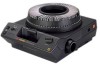
this will cause damage to the LAMP MODULE DOOR. [6] Remove the LAMP DOOR PLATE ASSEMBLY. SM5440-1 PROJECTOR LAMP LAMP EJECTOR LAMP SOCKET TERMINAL ASSEMBLY Important The EXTRA BRIGHT LAMP MODULE does not have a HEAT ABSORBING GLASS and has a LABEL on... ASSEMBLY in reverse order. 18 18NOV97 - Caution Remove the CONDENSER LENS and HEAT ABSORBING GLASS and set on a clean cloth. Do not set the parts on a cold surface; SERVICE MANUAL Replacing the LAMP SOCKET TERMINAL ASSEMBLY Style 1 LAMP SOCKET TERMINAL ASSEMBLY SCREW LAMP DOOR PLATE ASSEMBLY Warning Dangerous Voltage [1]...
this will cause damage to the LAMP MODULE DOOR. [6] Remove the LAMP DOOR PLATE ASSEMBLY. SM5440-1 PROJECTOR LAMP LAMP EJECTOR LAMP SOCKET TERMINAL ASSEMBLY Important The EXTRA BRIGHT LAMP MODULE does not have a HEAT ABSORBING GLASS and has a LABEL on... ASSEMBLY in reverse order. 18 18NOV97 - Caution Remove the CONDENSER LENS and HEAT ABSORBING GLASS and set on a clean cloth. Do not set the parts on a cold surface; SERVICE MANUAL Replacing the LAMP SOCKET TERMINAL ASSEMBLY Style 1 LAMP SOCKET TERMINAL ASSEMBLY SCREW LAMP DOOR PLATE ASSEMBLY Warning Dangerous Voltage [1]...
Service Manual
Page 36
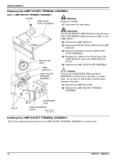
SM5440-1 see the illustrations. • FAN • INDEXER LEVER and TOP PLATE • WORM PULLEY ASSEMBLY • CAM STACK ASSEMBLY • CYCLE LEVERS • PIVOT SHAFT and LEVERS • LENS MOUNT ASSEMBLY A091_4037GA 36 18NOV97 - SERVICE MANUAL Section 3: Lubrication Apply lubricant SUPER LUBE TL-4276 to the following parts and areas of the projector;
SM5440-1 see the illustrations. • FAN • INDEXER LEVER and TOP PLATE • WORM PULLEY ASSEMBLY • CAM STACK ASSEMBLY • CYCLE LEVERS • PIVOT SHAFT and LEVERS • LENS MOUNT ASSEMBLY A091_4037GA 36 18NOV97 - SERVICE MANUAL Section 3: Lubrication Apply lubricant SUPER LUBE TL-4276 to the following parts and areas of the projector;
Service Manual
Page 39
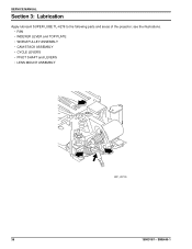
To operate the projector with the LOWER HOUSING removed, make a FAN COVER TOOL. FAN COVER TOOL 11.5 cm (4.5 in.) A091_0024GCA A091_0024GA SM5440-1 - 18NOV97 39 Section 4: Tools Tools TL-1744 TL-2264 TL-3002 TL-3003 TL-3005 TL-3255 TL-4276 Tool Description AUTO-FOCUS GAUGE FOCUS TEST (flat field) AUTO-FOCUS TARGET SLIDE ADJUSTMENT T-BAR ADJUSTMENT TOOL Torx DRIVER SET SUPER LUBE DIGITAL MULTIMETER Tools The LOWER HOUSING ASSEMBLY is a part of the cooling function. Cut here.
To operate the projector with the LOWER HOUSING removed, make a FAN COVER TOOL. FAN COVER TOOL 11.5 cm (4.5 in.) A091_0024GCA A091_0024GA SM5440-1 - 18NOV97 39 Section 4: Tools Tools TL-1744 TL-2264 TL-3002 TL-3003 TL-3005 TL-3255 TL-4276 Tool Description AUTO-FOCUS GAUGE FOCUS TEST (flat field) AUTO-FOCUS TARGET SLIDE ADJUSTMENT T-BAR ADJUSTMENT TOOL Torx DRIVER SET SUPER LUBE DIGITAL MULTIMETER Tools The LOWER HOUSING ASSEMBLY is a part of the cooling function. Cut here.
Service Manual
Page 46
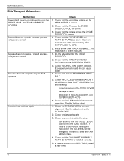
... Slide Transport Malfunctions Malfunction Forward and reverse do not operate using the FRONT PANEL BUTTONS or REMOTE CONTROL. Clean and lubricate the parts as necessary. Excessive lubrication and dirt can cause binds. 1. See the Voltage chart. 1. the malfunction is correct. 2. Reverse... does not operate, forward operates, voltages are correct. Projector does not complete a cycle; FAN operates. Check 1. Check that the voltage across the CYCLE SOLENOID COIL are clean. Check that the...
... Slide Transport Malfunctions Malfunction Forward and reverse do not operate using the FRONT PANEL BUTTONS or REMOTE CONTROL. Clean and lubricate the parts as necessary. Excessive lubrication and dirt can cause binds. 1. See the Voltage chart. 1. the malfunction is correct. 2. Reverse... does not operate, forward operates, voltages are correct. Projector does not complete a cycle; FAN operates. Check 1. Check that the voltage across the CYCLE SOLENOID COIL are clean. Check that the...
Service Manual
Page 48
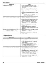
... 2. Malfunction No manual focus No remote focus (Non Auto Focus models) Check 1. Check the LENS SUPPORT SPRING for correct operation and install a new part if necessary. 2. Check the LENS DRIVE GEAR on CR3, Q3, and Q4, see the voltage table. 1. If the voltage is still a malfunction,...2. use a DVM to "S". • Check the voltages on the FOCUS SHAFT ASSEMBLY for damage and install a new part if necessary. 1. Move the TIMER BUTTON forward and backward; Energize the projector and move the TIMER to check for continuity between PINS 4 and 5 on the MAIN MOTOR is 6.7 V AC. ...
... 2. Malfunction No manual focus No remote focus (Non Auto Focus models) Check 1. Check the LENS SUPPORT SPRING for correct operation and install a new part if necessary. 2. Check the LENS DRIVE GEAR on CR3, Q3, and Q4, see the voltage table. 1. If the voltage is still a malfunction,...2. use a DVM to "S". • Check the voltages on the FOCUS SHAFT ASSEMBLY for damage and install a new part if necessary. 1. Move the TIMER BUTTON forward and backward; Energize the projector and move the TIMER to check for continuity between PINS 4 and 5 on the MAIN MOTOR is 6.7 V AC. ...