Service Manual
Page 3
General Parts 45 Power, Illumination, and Cooling Malfunctions 45 Slide Transport Malfunctions 46 Focus Malfunctions 48 SM5440-1 - 18NOV97 3 Auto Focus Models Adjustment Specification 28 Adjusting the NULL 29 Adjusting the PHOTOCELL 30 Adjusting the CLAMP PAD ASSEMBLY 34 Adjusting the DARK SHUTTER 34 Lubrication 36 Tools 39 Specifications 40 Diagnostics 42 MAIN MOTOR Voltages 42 PHOTOCELL Voltages 43 5-PIN REMOTE CORD PLUG Voltages 43 SMALL COMPONENT BOARD ASSEMBLY 256809 Voltages 44 Voltage Specifications - Adjusting the Focus Light Path -
General Parts 45 Power, Illumination, and Cooling Malfunctions 45 Slide Transport Malfunctions 46 Focus Malfunctions 48 SM5440-1 - 18NOV97 3 Auto Focus Models Adjustment Specification 28 Adjusting the NULL 29 Adjusting the PHOTOCELL 30 Adjusting the CLAMP PAD ASSEMBLY 34 Adjusting the DARK SHUTTER 34 Lubrication 36 Tools 39 Specifications 40 Diagnostics 42 MAIN MOTOR Voltages 42 PHOTOCELL Voltages 43 5-PIN REMOTE CORD PLUG Voltages 43 SMALL COMPONENT BOARD ASSEMBLY 256809 Voltages 44 Voltage Specifications - Adjusting the Focus Light Path -
Service Manual
Page 22
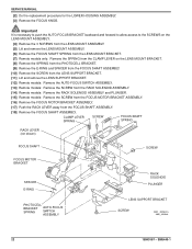
... the LENS MOUNT ASSEMBLY. [5] Lift and remove the LENS MOUNT ASSEMBLY. [6] Remove the FOCUS SHAFT SPRING from the LENS MOUNT BRACKET. [7] Remote models only: Remove the SPRING from the CLAMP LEVER on the LENS MOUNT BRACKET. [8] Remove the SPRING from the PHOTOCELL BRACKET. [9] Remove ...Lift and remove the LENS SUPPORT BRACKET. [12] Remote models: Remove the AUTO-FOCUS SWITCH ASSEMBLY. [13] Remote models: Remove the SCREW from the RACK SOLENOID ASSEMBLY. [14] Remote models: Remove the RACK SOLENOID ASSEMBLY and PLUNGER. [15] Remote models: Remove the SCREW from the FOCUS MOTOR BRACKET...
... the LENS MOUNT ASSEMBLY. [5] Lift and remove the LENS MOUNT ASSEMBLY. [6] Remove the FOCUS SHAFT SPRING from the LENS MOUNT BRACKET. [7] Remote models only: Remove the SPRING from the CLAMP LEVER on the LENS MOUNT BRACKET. [8] Remove the SPRING from the PHOTOCELL BRACKET. [9] Remove ...Lift and remove the LENS SUPPORT BRACKET. [12] Remote models: Remove the AUTO-FOCUS SWITCH ASSEMBLY. [13] Remote models: Remove the SCREW from the RACK SOLENOID ASSEMBLY. [14] Remote models: Remove the RACK SOLENOID ASSEMBLY and PLUNGER. [15] Remote models: Remove the SCREW from the FOCUS MOTOR BRACKET...

Service Manual
Page 34
... PRESSURE PAD to make a FAN COVER TOOL. See the Tools section. [4] Connect the REMOTE CONTROL ASSEMBLY EC-3 to adjust the pressure of the REMOTE FOCUS CLAMP on the CLAMP PAD ASSEMBLY. [7] Energize the REMOTE FOCUS in the MECHANISM GATE. If not, adjust the SCREW on the CLAMP PAD ASSEMBLY to...and the LAMP MODULE. Important It is correctly aligned with the DARK SHUTTER. Adjustment Specification The PRESSURE PAD should move . [9] Release the REMOTE FOCUS. [10] Tighten the NUT on the CLAMP PAD ASSEMBLY. [11] Install the AUTO-FOCUS GAUGE TL-1744 in either direction. [8] Rotate...
... PRESSURE PAD to make a FAN COVER TOOL. See the Tools section. [4] Connect the REMOTE CONTROL ASSEMBLY EC-3 to adjust the pressure of the REMOTE FOCUS CLAMP on the CLAMP PAD ASSEMBLY. [7] Energize the REMOTE FOCUS in the MECHANISM GATE. If not, adjust the SCREW on the CLAMP PAD ASSEMBLY to...and the LAMP MODULE. Important It is correctly aligned with the DARK SHUTTER. Adjustment Specification The PRESSURE PAD should move . [9] Release the REMOTE FOCUS. [10] Tighten the NUT on the CLAMP PAD ASSEMBLY. [11] Install the AUTO-FOCUS GAUGE TL-1744 in either direction. [8] Rotate...
Service Manual
Page 41
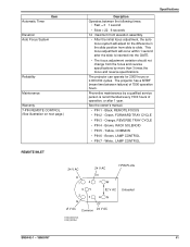
... = 22 6 seconds 14 maximum front elevation assembly. • After the initial focus adjustment, the autofocus system will occur within 1 second after 1 year. Black, REMOTE FOCUS • PIN 2 - Green, FORWARD TRAY CYCLE • PIN 3 - White, LAMP CONTROL Specifications 24 V AC K 1 24 V AC N 4 7W... SOLENOID • PIN 5 - Automatic Timer Item Elevation Auto Focus System Reliability Maintenance Warranty 7-PIN REMOTE CONTROL (See illustration on next page.) REMOTE INLET Desription Operates between failures) of operation, or after the slide is recommended every 1500 hours of...
... = 22 6 seconds 14 maximum front elevation assembly. • After the initial focus adjustment, the autofocus system will occur within 1 second after 1 year. Black, REMOTE FOCUS • PIN 2 - Green, FORWARD TRAY CYCLE • PIN 3 - White, LAMP CONTROL Specifications 24 V AC K 1 24 V AC N 4 7W... SOLENOID • PIN 5 - Automatic Timer Item Elevation Auto Focus System Reliability Maintenance Warranty 7-PIN REMOTE CONTROL (See illustration on next page.) REMOTE INLET Desription Operates between failures) of operation, or after the slide is recommended every 1500 hours of...

Service Manual
Page 44
... R12 ++ R11 R10 C3 C2 R13 R14 CR6 R15 Q4 Description TIMER Circuit TIMER Circuit TIMER Circuit CYCLE HOLD DOWN REVERSE FOCUS FOCUS RACK USE REMOTE FOCUS FOCUS Component CR3 Q3 Q4 CR4 CR2 CR5 Q1 Q2 RED +, BLACK + to + A 23.3 V DC 28.0 V DC A091_4034DC 44 18NOV97 - G to - G to + K + to - 28...
... R12 ++ R11 R10 C3 C2 R13 R14 CR6 R15 Q4 Description TIMER Circuit TIMER Circuit TIMER Circuit CYCLE HOLD DOWN REVERSE FOCUS FOCUS RACK USE REMOTE FOCUS FOCUS Component CR3 Q3 Q4 CR4 CR2 CR5 Q1 Q2 RED +, BLACK + to + A 23.3 V DC 28.0 V DC A091_4034DC 44 18NOV97 - G to - G to + K + to - 28...
Service Manual
Page 46
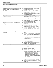
... the wires: • Use a tool to parts. 3. SERVICE MANUAL Slide Transport Malfunctions Malfunction Forward and reverse do not operate using the FRONT PANEL BUTTONS or REMOTE CONTROL. Check that the secondary voltage on the DIRECTION LEVER. 3. Check for binds. SM5440-1 the malfunction is correct. 1. See the Voltage chart. 1. Check that the...
... the wires: • Use a tool to parts. 3. SERVICE MANUAL Slide Transport Malfunctions Malfunction Forward and reverse do not operate using the FRONT PANEL BUTTONS or REMOTE CONTROL. Check that the secondary voltage on the DIRECTION LEVER. 3. Check for binds. SM5440-1 the malfunction is correct. 1. See the Voltage chart. 1. Check that the...
Service Manual
Page 47
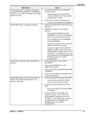
... parallel with the TOP HOUSING. the lower corner of the SLIDE LIFT LEVER; Malfunction The projector does not change cycles when using a DISSOLVE CONTROL; the REMOTE CONTROL and CONTROL PANEL BUTTONS operate correctly. The projector has power. Check the SLIDE TRAY LATCH for correct alignment. 2.
... parallel with the TOP HOUSING. the lower corner of the SLIDE LIFT LEVER; Malfunction The projector does not change cycles when using a DISSOLVE CONTROL; the REMOTE CONTROL and CONTROL PANEL BUTTONS operate correctly. The projector has power. Check the SLIDE TRAY LATCH for correct alignment. 2.
Service Manual
Page 48
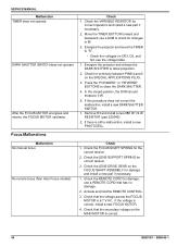
...SHAFT SPRING for correct operation and install a new part if necessary. 2. If the voltage is 6.7 V AC. Focus Malfunctions Check 1. use a REMOTE CORD that has no damage. 2. Energize the projector and move the TIMER to check for damage and install a new part if necessary. 1. Press.... 1. Remove R3 and install a new 68K W 1/4 W RESISTOR (part 220040). 2. Check the LENS SUPPORT SPRING for damage; Actuate and hold the REMOTE CONTROL. 3. In the closed position, the DVM should measure 0 W. 5. Check the LENS DRIVE GEAR on the SPECIAL APPLICATIONS PLUG. 3. SM5440-1 Malfunction No...
...SHAFT SPRING for correct operation and install a new part if necessary. 2. If the voltage is 6.7 V AC. Focus Malfunctions Check 1. use a REMOTE CORD that has no damage. 2. Energize the projector and move the TIMER to check for damage and install a new part if necessary. 1. Press.... 1. Remove R3 and install a new 68K W 1/4 W RESISTOR (part 220040). 2. Check the LENS SUPPORT SPRING for damage; Actuate and hold the REMOTE CONTROL. 3. In the closed position, the DVM should measure 0 W. 5. Check the LENS DRIVE GEAR on the SPECIAL APPLICATIONS PLUG. 3. SM5440-1 Malfunction No...
Service Manual
Page 49
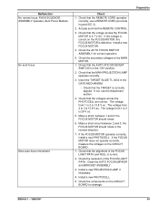
... 2. Check the resolution of the FOCUS LIGHT PATH and NULL is correctly aligned. Diagnostics SM5440-1 - 18NOV97 49 use a REMOTE CORD you know is 28 V ac. 5. Check that the REMOTE CORD operates correctly; Check that the voltage across the PHOTOCELL are correct. The voltage from 1 to 2 is in the "... on the FOCUS MOTOR, the FOCUS MOTOR is 6.7 V AC. If not, see the Adjustment section. 4. Make a short• between 2 and 3; Malfunction No remote focus, RACK SOLENOID ASSEMBLY operates (Auto Focus Models) No auto-focus Slow auto-focus movement Check 1. Actuate and hold the...
... 2. Check the resolution of the FOCUS LIGHT PATH and NULL is correctly aligned. Diagnostics SM5440-1 - 18NOV97 49 use a REMOTE CORD you know is 28 V ac. 5. Check that the REMOTE CORD operates correctly; Check that the voltage across the PHOTOCELL are correct. The voltage from 1 to 2 is in the "... on the FOCUS MOTOR, the FOCUS MOTOR is 6.7 V AC. If not, see the Adjustment section. 4. Make a short• between 2 and 3; Malfunction No remote focus, RACK SOLENOID ASSEMBLY operates (Auto Focus Models) No auto-focus Slow auto-focus movement Check 1. Actuate and hold the...
Service Manual
Page 50
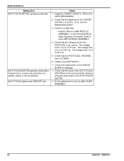
... HOUSING has 2 FILTERS. 6. Do the adjustment for damage. 1. If the FOCUS MOTOR stops operating continually, install a new LAMP MODULE ASSEMBLY. 4. SM5440-1 AUTO FOCUS adjusts after REMOTE use Check 1. If not, see the Adjustments section. 3. Check that the alignment of the AUTO FOCUS MOTOR are correct. The voltage from 2 to the mark...
... HOUSING has 2 FILTERS. 6. Do the adjustment for damage. 1. If the FOCUS MOTOR stops operating continually, install a new LAMP MODULE ASSEMBLY. 4. SM5440-1 AUTO FOCUS adjusts after REMOTE use Check 1. If not, see the Adjustments section. 3. Check that the alignment of the AUTO FOCUS MOTOR are correct. The voltage from 2 to the mark...

