
Owners Manual
Page 1
MONITOR TV MODELS M2262D M2262DP M2362D M2362DP M2762D M2762DP www.lg.com ENGLISH OWNER'S MANUAL MONITOR TV Please read this manual carefully before operating your set and retain it for future reference.
MONITOR TV MODELS M2262D M2262DP M2362D M2362DP M2762D M2762DP www.lg.com ENGLISH OWNER'S MANUAL MONITOR TV Please read this manual carefully before operating your set and retain it for future reference.
Owners Manual
Page 6
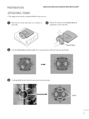
Stand Base 3 Turn the Stand Base Lock through 90° to separate the stand base from your set. 1 Place the set screen side down on a cushion or soft cloth. 2 Detach the monitor to the Stand Base by turning the screw to the left. PREPARATION DETACHING STAND I The image shown may be somewhat different from the stand body. OPEN OPEN OPEN OPEN 4 Pushing Latch inside, Take the stand base from stand body. OPEN OPEN Latch 5
Stand Base 3 Turn the Stand Base Lock through 90° to separate the stand base from your set. 1 Place the set screen side down on a cushion or soft cloth. 2 Detach the monitor to the Stand Base by turning the screw to the left. PREPARATION DETACHING STAND I The image shown may be somewhat different from the stand body. OPEN OPEN OPEN OPEN 4 Pushing Latch inside, Take the stand base from stand body. OPEN OPEN Latch 5
Owners Manual
Page 11
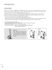
.... - Also, ensure that do not put your finger(s). Using screws that the set . You can hurt your finger(s)in between the head of the monitor and the stand body. Be sure to use screws and a wall mount that no bright light or sunlight falls directly onto the screen. RW120 RW240...damage the product or result in a position to follow these instructions. < Screw Mounting Interface Dimension > M2262D/M2362D/M2262DP/M2362DP : 100 mm x 100 mm hole spacing M2762D/M2762DP : 200 mm x 100 mm hole spacing * Wall mount interface(LG) : RW120 RW240 Warning: When adjusting the angle of air.
.... - Also, ensure that do not put your finger(s). Using screws that the set . You can hurt your finger(s)in between the head of the monitor and the stand body. Be sure to use screws and a wall mount that no bright light or sunlight falls directly onto the screen. RW120 RW240...damage the product or result in a position to follow these instructions. < Screw Mounting Interface Dimension > M2262D/M2362D/M2262DP/M2362DP : 100 mm x 100 mm hole spacing M2762D/M2762DP : 200 mm x 100 mm hole spacing * Wall mount interface(LG) : RW120 RW240 Warning: When adjusting the angle of air.
Owners Manual
Page 14
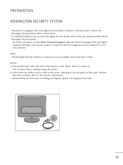
... Kensington Security System is nothing wrong with product. If the product feels cold to the user's guide provided with a Kensington Security System connector on the monitor's performance. b. Avoid touching the LCD screen or holding your finger(s) against it is equipped with the Kensington Security System. However, they have no adverse effect...
... Kensington Security System is nothing wrong with product. If the product feels cold to the user's guide provided with a Kensington Security System connector on the monitor's performance. b. Avoid touching the LCD screen or holding your finger(s) against it is equipped with the Kensington Security System. However, they have no adverse effect...
Owners Manual
Page 22
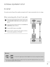
... EQUIPMENT SETUP PC SETUP This product provides Plug and Play capability, meaning that the PC adjusts automatically to the set can be operated as a PC monitor. When connecting with ferrite cores to select R G B. 4 Switch on the PC, and the PC screen appears on the set. G User must use shielded signal ...interface cables (D sub 15 pin cable, DVI cable) with a D-sub 15 pin cable 1 Connect the signal cable from the monitor output socket of the PERSONAL COMPUTER to the PC input socket of the set. 2 Connect the audio cable from the PC to the AUDIO IN...
... EQUIPMENT SETUP PC SETUP This product provides Plug and Play capability, meaning that the PC adjusts automatically to the set can be operated as a PC monitor. When connecting with ferrite cores to select R G B. 4 Switch on the PC, and the PC screen appears on the set. G User must use shielded signal ...interface cables (D sub 15 pin cable, DVI cable) with a D-sub 15 pin cable 1 Connect the signal cable from the monitor output socket of the PERSONAL COMPUTER to the PC input socket of the set. 2 Connect the audio cable from the PC to the AUDIO IN...
Owners Manual
Page 23
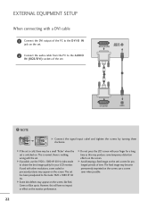
... is nothing wrong with the set 's screen for a long time as this will have no impact or effect on the monitor performance. G Do not press the LCD screen with your LCD monitor. G Avoid keeping a fixed image on the set . EXTERNAL EQUIPMENT SETUP When connecting with a DVI cable 1 Connect the DVI output of...
... is nothing wrong with the set 's screen for a long time as this will have no impact or effect on the monitor performance. G Do not press the LCD screen with your LCD monitor. G Avoid keeping a fixed image on the set . EXTERNAL EQUIPMENT SETUP When connecting with a DVI cable 1 Connect the DVI output of...
Owners Manual
Page 33
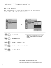
... . 3 ENTER 4 Select D T V, T V, CADTV, or C A T V. I A password is required to gain access to the Manual Tuning menu if the Lock System is turned on -screen signal strength monitor to the previous menu screen. 32 Channel 2 DTV 2-1 Bad Normal Good Add Close 1 MENU 2 ENTER Select CHANNEL. WATCHING TV / CHANNEL CONTROL MANUAL TUNING When selecting...
... . 3 ENTER 4 Select D T V, T V, CADTV, or C A T V. I A password is required to gain access to the Manual Tuning menu if the Lock System is turned on -screen signal strength monitor to the previous menu screen. 32 Channel 2 DTV 2-1 Bad Normal Good Add Close 1 MENU 2 ENTER Select CHANNEL. WATCHING TV / CHANNEL CONTROL MANUAL TUNING When selecting...
Owners Manual
Page 71
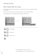
... or Off. OPTION SETTING DDC CI(Only RGB, DVI mode) DDC/CI (Display Data Channel Command Interface) is a communication protocol for communications between a PC and Monitor. OPTION Move Enter Language : English Input Label Key Lock : Off Caption : Off Set ID : 1 Power Indicator : On DDDC-CCII :: On Off OOnn E • Press the... the menu window. • Press the RETURN button to move to adjust and setup detailed functions on the PC. Off ignores the communications of the Monitor. On allows adjustments on the PC instead of DDC/CI data.
... or Off. OPTION SETTING DDC CI(Only RGB, DVI mode) DDC/CI (Display Data Channel Command Interface) is a communication protocol for communications between a PC and Monitor. OPTION Move Enter Language : English Input Label Key Lock : Off Caption : Off Set ID : 1 Power Indicator : On DDDC-CCII :: On Off OOnn E • Press the... the menu window. • Press the RETURN button to move to adjust and setup detailed functions on the PC. Off ignores the communications of the Monitor. On allows adjustments on the PC instead of DDC/CI data.

Owners Manual
Page 82
... connection status of the LCD. A See if the video card resolution and frequency are supported by the product. If the frequency is provided with the monitor. Try installing the latest drivers for the product is not properly communicating with the product, or download it Did you install the driver? After-image... mono color. Screen color is not a malfunction of the signal cable. Horizontal noise appears or the characters look blurred. from the web site. (http://www.lg.com) A The Video card in OSD. 81 settings on the background screen?
... connection status of the LCD. A See if the video card resolution and frequency are supported by the product. If the frequency is provided with the monitor. Try installing the latest drivers for the product is not properly communicating with the product, or download it Did you install the driver? After-image... mono color. Screen color is not a malfunction of the signal cable. Horizontal noise appears or the characters look blurred. from the web site. (http://www.lg.com) A The Video card in OSD. 81 settings on the background screen?


