
User Manual
Page 1
......8 1.3. Status LEDs...11 1.5. Multiple Power Supply Units 13 1.7.2. Dummy Drive Carrier Modules 15 1.9.4. Planning Your Installation...17 2.3. Rack Installation Pre-Requisites 19 2.4. Module Installation...20 2.6.1. Dummy Drive Carrier Modules 20 2.6.2. LaCie 12big Rack Network System Configurations 9 1.4. ATX Server Subsystem...10 1.4.1. Enclosure Rear Panel...12 1.7. Cooling Fans...14 1.9. Anti-tamper Locks...15 1.9.3. Installation...17 2.1. Introduction...17 2.2. Unpacking...
......8 1.3. Status LEDs...11 1.5. Multiple Power Supply Units 13 1.7.2. Dummy Drive Carrier Modules 15 1.9.4. Planning Your Installation...17 2.3. Rack Installation Pre-Requisites 19 2.4. Module Installation...20 2.6.1. Dummy Drive Carrier Modules 20 2.6.2. LaCie 12big Rack Network System Configurations 9 1.4. ATX Server Subsystem...10 1.4.1. Enclosure Rear Panel...12 1.7. Cooling Fans...14 1.9. Anti-tamper Locks...15 1.9.3. Installation...17 2.1. Introduction...17 2.2. Unpacking...
User Manual
Page 2
...-DIMM Memory Modules 42 5.5.2. Replacing the Boot Drives...45 Overview...26 4.1.1. Computer Doesn't Recognize the LaCie 12big Rack Network Subsystem 26 4.2. ATX Server LEDs...29 4.2.6.1. Drive Carrier Module Faults...34 4.7. Overview...35 5.2. Power Supply Units...36 5.3.1.1. Installing...Replacing a Module...35 5.3.1. Removing a Cooling Fan 38 5.3.2.2. Cooling Fan LEDs...28 4.2.4. Replacing ATX Motherboards...42 5.5.1. LaCie 12big Rack Network User Manual Table of Contents page 2 3.4.2. Status LEDs...29 4.2.6.2. Engaging the Drive Module Anti-tamper Locks 24 ...
...-DIMM Memory Modules 42 5.5.2. Replacing the Boot Drives...45 Overview...26 4.1.1. Computer Doesn't Recognize the LaCie 12big Rack Network Subsystem 26 4.2. ATX Server LEDs...29 4.2.6.1. Drive Carrier Module Faults...34 4.7. Overview...35 5.2. Power Supply Units...36 5.3.1.1. Installing...Replacing a Module...35 5.3.1. Removing a Cooling Fan 38 5.3.2.2. Cooling Fan LEDs...28 4.2.4. Replacing ATX Motherboards...42 5.5.1. LaCie 12big Rack Network User Manual Table of Contents page 2 3.4.2. Status LEDs...29 4.2.6.2. Engaging the Drive Module Anti-tamper Locks 24 ...
User Manual
Page 8
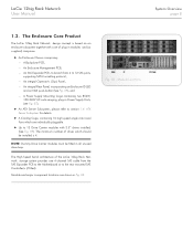
The Enclosure Core Product The LaCie 12big Rack Network design concept is 4. The minimum number of the LaCie 12big Rack Network storage system provides one 4-channel SAS cable from 4 to section 1.4. The High Speed Serial architecture of drives which are shown in Power Supply Units, (see Fig. 07), ✦✦ An ATX Server Subsystem, please refer to 12 SAS ports...
The Enclosure Core Product The LaCie 12big Rack Network design concept is 4. The minimum number of the LaCie 12big Rack Network storage system provides one 4-channel SAS cable from 4 to section 1.4. The High Speed Serial architecture of drives which are shown in Power Supply Units, (see Fig. 07), ✦✦ An ATX Server Subsystem, please refer to 12 SAS ports...

User Manual
Page 9
...chassis assembly accommodates two Power Supply Units and ATX Server Subsystem. Each drive bay accommodates a plug-in Drive Carrier Module which enables it to be fitted to standard 19 inch racks and uses 2 EIA units of rack space (i.e. 3.5" high). ✦✦ The ... single 1.0" high 3.5 inch disk drive in its carrier module. Enclosure Chassis There are offered: Table 01 - LaCie 12big Rack Network System Configurations The following LaCie 12big Rack Network system configurations are 12 drive bays at the front of a sheet metal enclosure assembly containing an integrated Backplane PCB,...
...chassis assembly accommodates two Power Supply Units and ATX Server Subsystem. Each drive bay accommodates a plug-in Drive Carrier Module which enables it to be fitted to standard 19 inch racks and uses 2 EIA units of rack space (i.e. 3.5" high). ✦✦ The ... single 1.0" high 3.5 inch disk drive in its carrier module. Enclosure Chassis There are offered: Table 01 - LaCie 12big Rack Network System Configurations The following LaCie 12big Rack Network system configurations are 12 drive bays at the front of a sheet metal enclosure assembly containing an integrated Backplane PCB,...
User Manual
Page 10
... service personnel as it provides access to the "locked" position with integral I /O Components ATX Server I /O panel. ✦✦ Slots for details of the cards used in the various configurations. (Blank PCI Plates are fitted in a vertical orientation. LaCie 12big Rack Network User Manual System Overview page 10 The top cover on the enclosure provides access...
... service personnel as it provides access to the "locked" position with integral I /O Components ATX Server I /O panel. ✦✦ Slots for details of the cards used in the various configurations. (Blank PCI Plates are fitted in a vertical orientation. LaCie 12big Rack Network User Manual System Overview page 10 The top cover on the enclosure provides access...

User Manual
Page 11
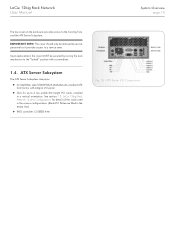
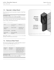
..., shown in Fig. 05. 1.4.2. Status LEDs The ATX Server I /O panel incorporates the following connectors: ✦✦ PS2 Mouse ✦✦ PS2 Keyboard ✦✦ Serial Port ✦✦ Video ✦✦ 2 x RJ45 -... components and to help you identify the server from among several servers. NIC LEDs The Network Interface Controller (NIC) LEDs at the right and left of each NIC socket provide the information shown in Table 11. NIC Ports 1 & 2 (1Gb) ✦✦ 4 x USB - ATX Server LEDs 1.4.2.1. LaCie 12big Rack Network User Manual 1.4.1. Table 10 summarizes the ...
..., shown in Fig. 05. 1.4.2. Status LEDs The ATX Server I /O panel incorporates the following connectors: ✦✦ PS2 Mouse ✦✦ PS2 Keyboard ✦✦ Serial Port ✦✦ Video ✦✦ 2 x RJ45 -... components and to help you identify the server from among several servers. NIC LEDs The Network Interface Controller (NIC) LEDs at the right and left of each NIC socket provide the information shown in Table 11. NIC Ports 1 & 2 (1Gb) ✦✦ 4 x USB - ATX Server LEDs 1.4.2.1. LaCie 12big Rack Network User Manual 1.4.1. Table 10 summarizes the ...
User Manual
Page 12
... Rear Panel LED Status Enclosure ID LED Blue (when activated) Activated by push button on the Ops Panel, or by system software. LaCie 12big Rack Network User Manual System Overview page 12 1.5. This assembly incorporates a USB socket, three LEDs and three push button switches, with the following ... IMPORTANT INFO: The Ops Panel is an integral part of the LED and switch functions. 1.6. Please refer to identify a server from among several servers IMPORTANT INFO: The Rear Panel is an integral part of the enclosure chassis assembly and is not field replaceable. Enclosure Front...
... Rear Panel LED Status Enclosure ID LED Blue (when activated) Activated by push button on the Ops Panel, or by system software. LaCie 12big Rack Network User Manual System Overview page 12 1.5. This assembly incorporates a USB socket, three LEDs and three push button switches, with the following ... IMPORTANT INFO: The Ops Panel is an integral part of the LED and switch functions. 1.6. Please refer to identify a server from among several servers IMPORTANT INFO: The Rear Panel is an integral part of the enclosure chassis assembly and is not field replaceable. Enclosure Front...
User Manual
Page 18
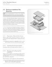
... installation is too heavy for information on your LaCie 12big Rack Network storage system has the following procedures describe the installation of Site and Host Server Before you begin installation you intend to 2.2. Enclosure Installation PreRequisites NOTE: LaCie 12big Rack Network enclosures are outlined in the easiest manner. Preparation of the LaCie 12big Rack Network enclosure and highlights any critical pre-requisite requirements...
... installation is too heavy for information on your LaCie 12big Rack Network storage system has the following procedures describe the installation of Site and Host Server Before you begin installation you intend to 2.2. Enclosure Installation PreRequisites NOTE: LaCie 12big Rack Network enclosures are outlined in the easiest manner. Preparation of the LaCie 12big Rack Network enclosure and highlights any critical pre-requisite requirements...

User Manual
Page 28
... system software. Used to identify a server from among several servers Fig. 18 - The LED conditions are defined in each Drive Carrier module, shown in Fig. 18. Rear Panel LED Table 09 - Drive Carrier Module Faults: 4.2.5. Cooling Fan LEDs An Amber LED incorporated in section 4.6. Drive carrier LEDs LaCie 12big Rack Network User Manual Troubleshooting & Problem Solving...
... system software. Used to identify a server from among several servers Fig. 18 - The LED conditions are defined in each Drive Carrier module, shown in Fig. 18. Rear Panel LED Table 09 - Drive Carrier Module Faults: 4.2.5. Cooling Fan LEDs An Amber LED incorporated in section 4.6. Drive carrier LEDs LaCie 12big Rack Network User Manual Troubleshooting & Problem Solving...

User Manual
Page 29
LaCie 12big Rack Network User Manual 4.2.6. NIC LEDs LED LED State Description Left Off No network connection is in place Solid green Active network connection is in Table 11. Status LEDs The ATX Motherboard I/O panel contains a number of the LED states. ATX Server Status LEDs LED System Status LED 4 x...toggle between red, green, amber and Off at boot up. *(Lit amber only if a failure occurs). 4.2.6.2. ATX Server LEDs 4.2.6.1. NIC LEDs The Network Interface Controller (NIC) LEDs are defined in place Blinking green Transmit / receive activity is occurring Right Off 10 Mbps ...
LaCie 12big Rack Network User Manual 4.2.6. NIC LEDs LED LED State Description Left Off No network connection is in place Solid green Active network connection is in Table 11. Status LEDs The ATX Motherboard I/O panel contains a number of the LED states. ATX Server Status LEDs LED System Status LED 4 x...toggle between red, green, amber and Off at boot up. *(Lit amber only if a failure occurs). 4.2.6.2. ATX Server LEDs 4.2.6.1. NIC LEDs The Network Interface Controller (NIC) LEDs are defined in place Blinking green Transmit / receive activity is occurring Right Off 10 Mbps ...

User Manual
Page 35
...Server Component Locations 5.3. CAUTION: Upon module replacement, the enclosure top cover MUST be secured by turning the lock mechanism to diagnose problems within the enclosure's power, cooling and drive systems. The sensors for each unit. 5.2. Replacing a Module CAUTION: Whenever replacing a module NEVER leave an EMPTY bay in modules and components. LaCie 12big Rack Network... User Manual Module Removal & Replacement page 35 5. Overview The LaCie 12big Rack Network Enclosure includes an Enclosure Services Processor and...
...Server Component Locations 5.3. CAUTION: Upon module replacement, the enclosure top cover MUST be secured by turning the lock mechanism to diagnose problems within the enclosure's power, cooling and drive systems. The sensors for each unit. 5.2. Replacing a Module CAUTION: Whenever replacing a module NEVER leave an EMPTY bay in modules and components. LaCie 12big Rack Network... User Manual Module Removal & Replacement page 35 5. Overview The LaCie 12big Rack Network Enclosure includes an Enclosure Services Processor and...
