
User Manual
Page 1
...7 1.2. ATX Server Subsystem...10 1.4.1. Status LEDs...11 1.5. Enclosure Management...16 2. Special Tools and Equipment 19 2.3.5. Operation...22 3.1. Power Supply Unit...13 1.7.1. Cooling Fans...14 1.9. Drive Carrier Module...15 1.9.1. Introduction...17 2.2. LaCie 12big Rack Network System Configurations 9 1.4. Dummy Drive Carrier Modules 15 1.9.4. Installation...17 2.1. Starting the Drives...24 3.4.1. LaCie 12big Rack Network User Manual Table of Contents page 1 Table of Site and Host Server 18 2.3.2. Parts Check List...20 2.7.2. Disk Drive LEDs...24
...7 1.2. ATX Server Subsystem...10 1.4.1. Status LEDs...11 1.5. Enclosure Management...16 2. Special Tools and Equipment 19 2.3.5. Operation...22 3.1. Power Supply Unit...13 1.7.1. Cooling Fans...14 1.9. Drive Carrier Module...15 1.9.1. Introduction...17 2.2. LaCie 12big Rack Network System Configurations 9 1.4. Dummy Drive Carrier Modules 15 1.9.4. Installation...17 2.1. Starting the Drives...24 3.4.1. LaCie 12big Rack Network User Manual Table of Contents page 1 Table of Site and Host Server 18 2.3.2. Parts Check List...20 2.7.2. Disk Drive LEDs...24
User Manual
Page 2
...Module Replacement 35 5.1. Installing a Drive Carrier 40 5.4. ATX Server LEDs...29 4.2.6.1. Power Supply Unit Faults 32 4.5.3. Installing a Power Supply Unit 37 5.3.2. Removing a Cooling Fan 38 5.3.2.2. Replacing ATX Motherboards...42 5.5.1. Replacing PCI Cards...43 5.6.1. Cooling Fan LEDs...28 4.2.4. Thermal Alarm...33 4.6. Replacing a Module...35 5.3.1. Installing a Cooling Fan 39 5.3.3. Replacing the Boot Drives...45 LaCie 12big Rack Network User Manual Table of Contents page 2 3.4.2. Power Down...25 4. Alarm Sounds On Power Up 26 4.1.1.3. LED States...
...Module Replacement 35 5.1. Installing a Drive Carrier 40 5.4. ATX Server LEDs...29 4.2.6.1. Power Supply Unit Faults 32 4.5.3. Installing a Power Supply Unit 37 5.3.2. Removing a Cooling Fan 38 5.3.2.2. Replacing ATX Motherboards...42 5.5.1. Replacing PCI Cards...43 5.6.1. Cooling Fan LEDs...28 4.2.4. Thermal Alarm...33 4.6. Replacing a Module...35 5.3.1. Installing a Cooling Fan 39 5.3.3. Replacing the Boot Drives...45 LaCie 12big Rack Network User Manual Table of Contents page 2 3.4.2. Power Down...25 4. Alarm Sounds On Power Up 26 4.1.1.3. LED States...
User Manual
Page 3
Data Drives...49 6.7.2. Boot Drives...49 6.8. International Standards...50 7.2. ESD Precautions...50 7.5. Warranty Information 55 Technical Specifications 47 6.1. Cooling Fan...49 6.6. EMC Compliance...51 7.7. Rail Kit Installation...52 9. LaCie 12big Rack Network User Manual Table of Waste Electrical and Electronic Equipment (WEEE 51 8. Drives...49 6.7.1. Standards & Regulations 50 7.1. Potential for Radio Frequency Interference 50 7.3. Safety Compliance...50 7.6. Contacting Customer Support 54 9.1. RAID Card Options...49 7. LaCie Technical Support ...
Data Drives...49 6.7.2. Boot Drives...49 6.8. International Standards...50 7.2. ESD Precautions...50 7.5. Warranty Information 55 Technical Specifications 47 6.1. Cooling Fan...49 6.6. EMC Compliance...51 7.7. Rail Kit Installation...52 9. LaCie 12big Rack Network User Manual Table of Waste Electrical and Electronic Equipment (WEEE 51 8. Drives...49 6.7.1. Standards & Regulations 50 7.1. Potential for Radio Frequency Interference 50 7.3. Safety Compliance...50 7.6. Contacting Customer Support 54 9.1. RAID Card Options...49 7. LaCie Technical Support ...
User Manual
Page 4
... guide, do not have a working knowledge of Intel Corporation or its subsidiaries in any form, or by -step instructions on how to install, configure and connect the LaCie 12big Rack Network storage subsystem to your host computer system, and how to use this document is subject to which that person may arise. Other names and brands may be claimed as follows: ✦✦ Service...
... guide, do not have a working knowledge of Intel Corporation or its subsidiaries in any form, or by -step instructions on how to install, configure and connect the LaCie 12big Rack Network storage subsystem to your host computer system, and how to use this document is subject to which that person may arise. Other names and brands may be claimed as follows: ✦✦ Service...
User Manual
Page 5
... in a Power Supply Mounting Cage. Environment. ✦✦ A safe electrical earth connection must be fitted to unused drive bays. Please refer to lift it . It is ESSENTIAL that the socket outlets are located near the equipment and are easily accessible. ✦✦ This equipment is intended to operate with the manufacturer's instructions and National regulations. LaCie 12big Rack Network User Manual Foreword page...
... in a Power Supply Mounting Cage. Environment. ✦✦ A safe electrical earth connection must be fitted to unused drive bays. Please refer to lift it . It is ESSENTIAL that the socket outlets are located near the equipment and are easily accessible. ✦✦ This equipment is intended to operate with the manufacturer's instructions and National regulations. LaCie 12big Rack Network User Manual Foreword page...
User Manual
Page 6
...power supplies in all modules and drives, to prevent the rack from the top down. ✦✦ Always remove all the units. It must provide overcurrent protection for the unit and must provide a reliable earth for the unit, which is mounted in a rack. ✦✦ The rack construction must take into a rack. CAUTION: To avoid danger of 1.4mA. Earth connection...cabinet at any one time. ✦✦ The system must meet the safety requirements of units installed in the rack. LaCie 12big Rack Network User Manual Foreword page 6 Rack System Safety Precautions ...
...power supplies in all modules and drives, to prevent the rack from the top down. ✦✦ Always remove all the units. It must provide overcurrent protection for the unit and must provide a reliable earth for the unit, which is mounted in a rack. ✦✦ The rack construction must take into a rack. CAUTION: To avoid danger of 1.4mA. Earth connection...cabinet at any one time. ✦✦ The system must meet the safety requirements of units installed in the rack. LaCie 12big Rack Network User Manual Foreword page 6 Rack System Safety Precautions ...

User Manual
Page 7
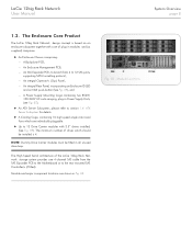
... Rear View Showing Service Areas System Overview 1.1. Fig. 01 shows a front view of an LaCie 12big Rack Network enclosure while Fig. 02 depicts a rear view with the lid removed, showing those areas accessible to 7200 rpm) Each individual disc drive is a 2U (rack space) disk drive enclosure, currently housing up to twelve low profile (1 inch high), 3.5 inch form factor drives as follows: ✦✦ 1.5/3.0Gb/s SATA (up to service personnel only. LaCie 12big Rack Network User Manual...
... Rear View Showing Service Areas System Overview 1.1. Fig. 01 shows a front view of an LaCie 12big Rack Network enclosure while Fig. 02 depicts a rear view with the lid removed, showing those areas accessible to 7200 rpm) Each individual disc drive is a 2U (rack space) disk drive enclosure, currently housing up to twelve low profile (1 inch high), 3.5 inch form factor drives as follows: ✦✦ 1.5/3.0Gb/s SATA (up to service personnel only. LaCie 12big Rack Network User Manual...
User Manual
Page 8
... minimum number of the LaCie 12big Rack Network storage system provides one 4-channel SAS cable from 4 to the rear mounted SAS Controller/s (if fitted). NOTE: Dummy Drive Carrier modules must be installed is based on an enclosure subsystem together with 3.5" drives installed, (See Fig. 09). The High Speed Serial architecture of drives which are shown in Power Supply Units, (see Fig. 07), ✦✦ An ATX Server...
... minimum number of the LaCie 12big Rack Network storage system provides one 4-channel SAS cable from 4 to the rear mounted SAS Controller/s (if fitted). NOTE: Dummy Drive Carrier modules must be installed is based on an enclosure subsystem together with 3.5" drives installed, (See Fig. 09). The High Speed Serial architecture of drives which are shown in Power Supply Units, (see Fig. 07), ✦✦ An ATX Server...

User Manual
Page 9
... rack space (i.e. 3.5" high). ✦✦ The Backplane PCB provides 12 direct dock SAS Serial ATA connectors to the drives and acts as the space required to the system via the Enclosure Management PCB. The chassis is defined as the connectivity hub of the enclosure, connecting to the Enclosure Management PCB. ✦✦ The ten Cooling Fans are offered: Table 01 - LaCie 12big Rack Network User Manual...
... rack space (i.e. 3.5" high). ✦✦ The Backplane PCB provides 12 direct dock SAS Serial ATA connectors to the drives and acts as the space required to the system via the Enclosure Management PCB. The chassis is defined as the connectivity hub of the enclosure, connecting to the Enclosure Management PCB. ✦✦ The ten Cooling Fans are offered: Table 01 - LaCie 12big Rack Network User Manual...
User Manual
Page 10
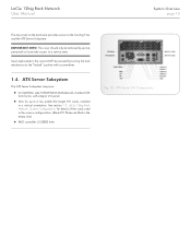
... replacement, the cover MUST be removed by turning the lock mechanism to a service area. LaCie 12big Rack Network System Configurations for up to the Cooling Fans and the ATX Server Subsystem. ATX Server I /O panel. ✦✦ Slots for details of the cards used in the various configurations. (Blank PCI Plates are fitted in a vertical orientation. See section 1.3. IMPORTANT INFO: The cover should only be secured...
... replacement, the cover MUST be removed by turning the lock mechanism to a service area. LaCie 12big Rack Network System Configurations for up to the Cooling Fans and the ATX Server Subsystem. ATX Server I /O panel. ✦✦ Slots for details of the cards used in the various configurations. (Blank PCI Plates are fitted in a vertical orientation. See section 1.3. IMPORTANT INFO: The cover should only be secured...
User Manual
Page 12
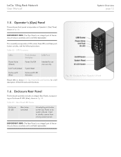
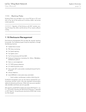
LaCie 12big Rack Network User Manual System Overview page 12 1.5. IMPORTANT INFO: The Ops Panel is an integral part of the enclosure chassis assembly and is not field replaceable. OPS Functions LEDs Push-button Switches Power Active (Green) Power On/Off Unit Fault (Amber) System Reset Enclosure ID (Blue) Enclosure ID LED Activation USB Port Intended for a full description of the LED and switch functions. 1.6. Enclosure Rear Panel The enclosure assembly includes an integral...
LaCie 12big Rack Network User Manual System Overview page 12 1.5. IMPORTANT INFO: The Ops Panel is an integral part of the enclosure chassis assembly and is not field replaceable. OPS Functions LEDs Push-button Switches Power Active (Green) Power On/Off Unit Fault (Amber) System Reset Enclosure ID (Blue) Enclosure ID LED Activation USB Port Intended for a full description of the LED and switch functions. 1.6. Enclosure Rear Panel The enclosure assembly includes an integral...

User Manual
Page 14
... axial fans, individually connected to the fans and returns tacho output from each fan Fig. 08 - This interface provides power and speed control to and interfacing with cooling air being drawn across the drives, through the PSU and minimizes noise. LaCie 12big Rack Network User Manual System Overview page 14 1.7.2. The cooling system must be operated with low pressure rear exhaust installation [Back pressure created by rack...
... axial fans, individually connected to the fans and returns tacho output from each fan Fig. 08 - This interface provides power and speed control to and interfacing with cooling air being drawn across the drives, through the PSU and minimizes noise. LaCie 12big Rack Network User Manual System Overview page 14 1.7.2. The cooling system must be operated with low pressure rear exhaust installation [Back pressure created by rack...
User Manual
Page 16
... temperature ✦✦ 3.5" HDD presence detection ✦✦ 3.5" HDD Fault LED control ✦✦ Front panel LED's and switches (including Enclosure Fault In- Download of drive bays etc. System Overview page 16 CAUTION: Operation of the enclosure to store system setup parameters -- No Operating System should be stopped. LaCie 12big Rack Network User Manual 1.9.4. Blanking Plates Blanking Plates must be required to the enclosure firmware.
... temperature ✦✦ 3.5" HDD presence detection ✦✦ 3.5" HDD Fault LED control ✦✦ Front panel LED's and switches (including Enclosure Fault In- Download of drive bays etc. System Overview page 16 CAUTION: Operation of the enclosure to store system setup parameters -- No Operating System should be stopped. LaCie 12big Rack Network User Manual 1.9.4. Blanking Plates Blanking Plates must be required to the enclosure firmware.
User Manual
Page 17
... to plan and install your LaCie 12big Rack Network system. CAUTION: When connecting up the LaCie 12big Rack Network subsystem, use only the power cords supplied or cords which match the specification quoted in Fig. 11. No bays should be fitted with blanking plates. Two Power Supply Units must be performed by Service Personnel Only. Module locations Installation page 17 LaCie 12big Rack Network User Manual 2. Planning Your Installation Before you begin installation you are located...
... to plan and install your LaCie 12big Rack Network system. CAUTION: When connecting up the LaCie 12big Rack Network subsystem, use only the power cords supplied or cords which match the specification quoted in Fig. 11. No bays should be fitted with blanking plates. Two Power Supply Units must be performed by Service Personnel Only. Module locations Installation page 17 LaCie 12big Rack Network User Manual 2. Planning Your Installation Before you begin installation you are located...
User Manual
Page 18
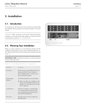
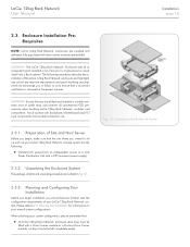
..., etc. 2.3.1. Planning and Configuring Your Installation Before you begin installation you should be left completely empty. Fig. 12 - LaCie 12big Rack Network User Manual Installation page 18 2.3. Enclosure Installation PreRequisites NOTE: LaCie 12big Rack Network enclosures are outlined in the easiest manner. CAUTION: The LaCie 12big Rack Network Enclosure with drive carrier modules preinstalled. Preparation of your LaCie 12big Rack Network storage system has the following procedures describe the installation of the LaCie 12big Rack Network enclosure and highlights any...
..., etc. 2.3.1. Planning and Configuring Your Installation Before you begin installation you should be left completely empty. Fig. 12 - LaCie 12big Rack Network User Manual Installation page 18 2.3. Enclosure Installation PreRequisites NOTE: LaCie 12big Rack Network enclosures are outlined in the easiest manner. CAUTION: The LaCie 12big Rack Network Enclosure with drive carrier modules preinstalled. Preparation of your LaCie 12big Rack Network storage system has the following procedures describe the installation of the LaCie 12big Rack Network enclosure and highlights any...
User Manual
Page 19
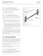
.... Use of other mounting hardware may be installed without loss of 5 pascals (0.5mm water gauge). LaCie 12big Rack Network User Manual Installation page 19 2.3.4. Special Tools and Equipment There are available for installation into an industry standard 19 inch cabinet capable of holding the unit. ✦✦ Minimum depth 707mm (27.83 inches) from rack posts to maximum extremity of enclosure (excludes rear cabling...
.... Use of other mounting hardware may be installed without loss of 5 pascals (0.5mm water gauge). LaCie 12big Rack Network User Manual Installation page 19 2.3.4. Special Tools and Equipment There are available for installation into an industry standard 19 inch cabinet capable of holding the unit. ✦✦ Minimum depth 707mm (27.83 inches) from rack posts to maximum extremity of enclosure (excludes rear cabling...

User Manual
Page 20
... Dummy Drive Carrier modules must always be used with Backplane PCB, ATX Motherboard, Enclosure Management PCB, SAS Expander PCB, Ops Panel, Intel® RAID Controller (optional), Battery Backup Unit (optional), Blank Plates (covering empty PCI slots) and all unused drive bays to 4. Power Cord Connection 2.7.1. Parts Check List ✦✦ Power cords to fans. LaCie 12big Rack Network User Manual Installation page 20 2.5. Withdraw chassis until it reaches hard stops...
... Dummy Drive Carrier modules must always be used with Backplane PCB, ATX Motherboard, Enclosure Management PCB, SAS Expander PCB, Ops Panel, Intel® RAID Controller (optional), Battery Backup Unit (optional), Blank Plates (covering empty PCI slots) and all unused drive bays to 4. Power Cord Connection 2.7.1. Parts Check List ✦✦ Power cords to fans. LaCie 12big Rack Network User Manual Installation page 20 2.5. Withdraw chassis until it reaches hard stops...

User Manual
Page 31
... Meaning Failure State - LaCie 12big Rack Network User Manual Troubleshooting & Problem Solving page 31 LED/Buzzer Fan Light Drive Light (amber) Ops Panel Ident LED Buzzer State Constant On Constant On Flashing Constant On Flashing Flashing Off Off Intermittent short beep (0.5 second beep every 32 seconds) Slow beep (half second beep every 8 seconds). Various Ops Panel Fault light flash states Ops Panel Fault LED slow blink (0.5 seconds On, 3.5 seconds Off). Replace Fans immediately. Check fault status using...
... Meaning Failure State - LaCie 12big Rack Network User Manual Troubleshooting & Problem Solving page 31 LED/Buzzer Fan Light Drive Light (amber) Ops Panel Ident LED Buzzer State Constant On Constant On Flashing Constant On Flashing Flashing Off Off Intermittent short beep (0.5 second beep every 32 seconds) Slow beep (half second beep every 8 seconds). Various Ops Panel Fault light flash states Ops Panel Fault LED slow blink (0.5 seconds On, 3.5 seconds Off). Replace Fans immediately. Check fault status using...

User Manual
Page 33
... FAULT LED amber. 2. If the internal temperature measured in place. 5. A minimum gap of 25mm at the front and 50mm at either the front or rear of drives and power supplies fitted. 1. LaCie 12big Rack Network User Manual Troubleshooting & Problem Solving page 33 4.5.4. Note: This threshold changes according to dust build-up , clean as appropriate. 3. Check that all Blank modules are observed to the front, use...
... FAULT LED amber. 2. If the internal temperature measured in place. 5. A minimum gap of 25mm at the front and 50mm at either the front or rear of drives and power supplies fitted. 1. LaCie 12big Rack Network User Manual Troubleshooting & Problem Solving page 33 4.5.4. Note: This threshold changes according to dust build-up , clean as appropriate. 3. Check that all Blank modules are observed to the front, use...

User Manual
Page 53
... RACK POST SUPPLY COMPONENTS IN I ASSEMBLY INSTRUCTIONS 1. RETURN CHASSIS TO FULLY HOME POSITION AND ATTACH TO RACK USING CAPTIVE FASTENERS ON FRONT FLANGES. 4. K LIFT CHASSIS AND ALIGN WITH RACK RAILS, CAREFULLY INSERT CHASSIS SLIDES INTO RACK RAILS AND PUSH FULLY HOME. MOUNTING CHASSIS INTO RACK. TIGHTEN REAR SCREWS, WITHDRAW CHASSIS UNTIL IT REACHES HARD STOPS (APPROX 400mm). LaCie 12big Rack Network User Manual Fig. 38 - Rail Kit Installation Drawing PART...
... RACK POST SUPPLY COMPONENTS IN I ASSEMBLY INSTRUCTIONS 1. RETURN CHASSIS TO FULLY HOME POSITION AND ATTACH TO RACK USING CAPTIVE FASTENERS ON FRONT FLANGES. 4. K LIFT CHASSIS AND ALIGN WITH RACK RAILS, CAREFULLY INSERT CHASSIS SLIDES INTO RACK RAILS AND PUSH FULLY HOME. MOUNTING CHASSIS INTO RACK. TIGHTEN REAR SCREWS, WITHDRAW CHASSIS UNTIL IT REACHES HARD STOPS (APPROX 400mm). LaCie 12big Rack Network User Manual Fig. 38 - Rail Kit Installation Drawing PART...


