UDS1100/UDS2100 - Product Brief
Page 1
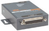
... equipped with Lantronix' TruPort® COM Port Redirector software, UDS creates a fully transparent serial connection to existing PC-based software applications-making it possible to remotely connect to equipment already in the field as if it were connected to a local PC serial port. UDS1100/2100 Family Serial Device Servers RELIABLE DEVICE SERVERS FOR AFFORDABLE SERIAL-TO-ETHERNET CONNECTIVITY The UDS...
... equipped with Lantronix' TruPort® COM Port Redirector software, UDS creates a fully transparent serial connection to existing PC-based software applications-making it possible to remotely connect to equipment already in the field as if it were connected to a local PC serial port. UDS1100/2100 Family Serial Device Servers RELIABLE DEVICE SERVERS FOR AFFORDABLE SERIAL-TO-ETHERNET CONNECTIVITY The UDS...

UDS1100/UDS2100 - Product Brief
Page 2
...-240 VAC International power supply with shield connected to chassis ground ORDERING INFORMATION + Part Number + Description UD1100001-01 UDS1100 one-port device server - no enclosure) UD2100001-01 UDS2100 two-port device server - DB9F-to -DB25M serial cable (P/N 500-163-R) - All rights...TCP, UDP, and Telnet, TFTP, RFC2217 + LED Indicators • Power, Link, Activity, RX Activity, TX Activity + Processor • CPU: Lantronix DSTNI-EX 48 MHz clock • Memory: 256 KB SRAM, 2 MB Flash + Power Requirements • Input supply: 9-30 VDC (PoE ...
...-240 VAC International power supply with shield connected to chassis ground ORDERING INFORMATION + Part Number + Description UD1100001-01 UDS1100 one-port device server - no enclosure) UD2100001-01 UDS2100 two-port device server - DB9F-to -DB25M serial cable (P/N 500-163-R) - All rights...TCP, UDP, and Telnet, TFTP, RFC2217 + LED Indicators • Power, Link, Activity, RX Activity, TX Activity + Processor • CPU: Lantronix DSTNI-EX 48 MHz clock • Memory: 256 KB SRAM, 2 MB Flash + Power Requirements • Input supply: 9-30 VDC (PoE ...
UDS1100 - Quick Start Guide
Page 5
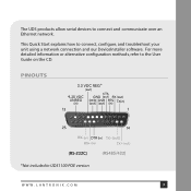
This Quick Start explains how to the User Guide on the CD. PINOUTS * *Not included in UDS1100 POE version WWW.LANTRONIX.COM 3 For more detailed information or alternative configuration methods, refer to connect, configure, and troubleshoot your unit using a network connection and our DeviceInstaller software. The UDS products allow serial devices to connect and communicate over an Ethernet network.
This Quick Start explains how to the User Guide on the CD. PINOUTS * *Not included in UDS1100 POE version WWW.LANTRONIX.COM 3 For more detailed information or alternative configuration methods, refer to connect, configure, and troubleshoot your unit using a network connection and our DeviceInstaller software. The UDS products allow serial devices to connect and communicate over an Ethernet network.
UDS1100 - Quick Start Guide
Page 7
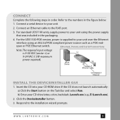
... the DeviceInstaller button. 3. WWW.LANTRONIX.COM 5 Refer to your unit using an 802.3af POE compliant power source such as a POE mid- Connect a serial device to the numbers in order. For the UDS1100-POE version, power is 9-30 VDC (center +) or 9-24 VAC (1.5W maximum power required). Ethernet, Power, and Serial Connections Note: The required input...
... the DeviceInstaller button. 3. WWW.LANTRONIX.COM 5 Refer to your unit using an 802.3af POE compliant power source such as a POE mid- Connect a serial device to the numbers in order. For the UDS1100-POE version, power is 9-30 VDC (center +) or 9-24 VAC (1.5W maximum power required). Ethernet, Power, and Serial Connections Note: The required input...

UDS1100 - Quick Start Guide
Page 14
SERIAL LEDS 10/100 Mb Link steady green 10/100 Activity blinking Diagnostic steady red and status blinking green Diagnostic blinking red and Status blinking green Status steady green Status blinking green Quick Start Guide UDS1100 MEANING Valid network connection Network packets transmitting and receiving 3 blinks = Network controller error 4 blinks = EEPROM checksum error 5 blinks = Duplicate IP address on network 5 blinks = No DHCP response Serial port not connected to network Serial port connected to network 12
SERIAL LEDS 10/100 Mb Link steady green 10/100 Activity blinking Diagnostic steady red and status blinking green Diagnostic blinking red and Status blinking green Status steady green Status blinking green Quick Start Guide UDS1100 MEANING Valid network connection Network packets transmitting and receiving 3 blinks = Network controller error 4 blinks = EEPROM checksum error 5 blinks = Duplicate IP address on network 5 blinks = No DHCP response Serial port not connected to network Serial port connected to network 12

UDS1100 - User Guide
Page 3
... Step 20 Assigning the IP Address: Serial Port Login 21 5: Configuration Using Web-Manager 22 Accessing UDS1100 Using DeviceInstaller 22 Network Configuration 24 Network Mode 24 Automatic IP Address Configuration 24 Static IP Address Configuration 25 Ethernet Configuration 26 Server Configuration 26 Host List Configuration 27 Channel 1 Configuration 28 Serial Settings 28 Connection Settings -
... Step 20 Assigning the IP Address: Serial Port Login 21 5: Configuration Using Web-Manager 22 Accessing UDS1100 Using DeviceInstaller 22 Network Configuration 24 Network Mode 24 Automatic IP Address Configuration 24 Static IP Address Configuration 25 Ethernet Configuration 26 Server Configuration 26 Host List Configuration 27 Channel 1 Configuration 28 Serial Settings 28 Connection Settings -

UDS1100 - User Guide
Page 4
... Timeout In Seconds 55 Monitor Mode at Bootup 55 HTTP Port Number 56 UDS1100 User Guide 4 UDP 34 Apply Settings 35 Apply Defaults 35 6: Configuration via Telnet or Serial Port (Setup Mode) 36 Accessing Setup Mode 36 Telnet Connection 36 Serial Port Connection 37 Exiting Setup Mode 37 7: Setup Mode: Server Configuration 38 Server Configuration...
... Timeout In Seconds 55 Monitor Mode at Bootup 55 HTTP Port Number 56 UDS1100 User Guide 4 UDP 34 Apply Settings 35 Apply Defaults 35 6: Configuration via Telnet or Serial Port (Setup Mode) 36 Accessing Setup Mode 36 Telnet Connection 36 Serial Port Connection 37 Exiting Setup Mode 37 7: Setup Mode: Server Configuration 38 Server Configuration...
UDS1100 - User Guide
Page 5
...56 TCP Re-Transmission Timeout 56 Enable alternate MAC 56 Ethernet Connection Type 56 Security Settings (Option 6 57 Disable SNMP 57 SNMP...Command Line Interface 62 Recovering the Firmware Using the Serial Port and DeviceInstaller _________ 62 11: Monitor Mode 64 Entering Monitor Mode Using the Serial Port 64 Entering Monitor Mode Using the Network ... Contact Information 67 LEDs 67 Problems and Error Messages 68 Technical Support 70 B: Connections and Pinouts 71 Serial Port 71 Serial Connector Pinouts 71 Modem Cable 72 Network Port 73 Ethernet Connector Pinouts 74 Power ...
...56 TCP Re-Transmission Timeout 56 Enable alternate MAC 56 Ethernet Connection Type 56 Security Settings (Option 6 57 Disable SNMP 57 SNMP...Command Line Interface 62 Recovering the Firmware Using the Serial Port and DeviceInstaller _________ 62 11: Monitor Mode 64 Entering Monitor Mode Using the Serial Port 64 Entering Monitor Mode Using the Network ... Contact Information 67 LEDs 67 Problems and Error Messages 68 Technical Support 70 B: Connections and Pinouts 71 Serial Port 71 Serial Connector Pinouts 71 Modem Cable 72 Network Port 73 Ethernet Connector Pinouts 74 Power ...

UDS1100 - User Guide
Page 7
... Address 13 Figure 3-1. Standard UDS1100 Connected to Serial Device and Network ______ 14 Figure 3-2. Channel Serial Settings 29 Figure 5-7. Apply Settings and Apply Defaults 35 Figure 6-1. Hostlist Option 46 Figure 9-1. DB25 Female DCE Interface RS232 71 Figure B-3. Firmware Files 61 Table 11-1. UDS1100 LEDs 67 Table A-2. Lantronix Web-Manager 23 Figure 5-3. UDP Connection Settings 34 Figure 5-9. Network...
... Address 13 Figure 3-1. Standard UDS1100 Connected to Serial Device and Network ______ 14 Figure 3-2. Channel Serial Settings 29 Figure 5-7. Apply Settings and Apply Defaults 35 Figure 6-1. Hostlist Option 46 Figure 9-1. DB25 Female DCE Interface RS232 71 Figure B-3. Firmware Files 61 Table 11-1. UDS1100 LEDs 67 Table A-2. Lantronix Web-Manager 23 Figure 5-3. UDP Connection Settings 34 Figure 5-9. Network...

UDS1100 - User Guide
Page 8
... of UDS1100 Provides information...UDS1100 device server. D: Mounting Brackets Provides drawings and dimensions of connection hardware. UDS1100...Serial Port (Setup Mode interface) using a Telnet connection through the network or a terminal or terminal emulation program through the serial... port. 6: Setup Mode: Server Configuration Details the network (server) settings 7: Setup Mode: Channel Configuration Details the serial...serial port connection. 4: Configuration Using Web- B: Connections...
... of UDS1100 Provides information...UDS1100 device server. D: Mounting Brackets Provides drawings and dimensions of connection hardware. UDS1100...Serial Port (Setup Mode interface) using a Telnet connection through the network or a terminal or terminal emulation program through the serial... port. 6: Setup Mode: Server Configuration Details the network (server) settings 7: Setup Mode: Channel Configuration Details the serial...serial port connection. 4: Configuration Using Web- B: Connections...

UDS1100 - User Guide
Page 10
..., RS422, or RS485 device Application Examples Using a method called serial tunneling, the UDS encapsulates serial data into packets and transports them over Ethernet. UDS1100 User Guide 10 Using two UDS units, connected by a network, virtual serial connections can extend across a facility or around the world. 2: Introduction The UDS1100 is a single-port device server that provides a quick, simple...
..., RS422, or RS485 device Application Examples Using a method called serial tunneling, the UDS encapsulates serial data into packets and transports them over Ethernet. UDS1100 User Guide 10 Using two UDS units, connected by a network, virtual serial connections can extend across a facility or around the world. 2: Introduction The UDS1100 is a single-port device server that provides a quick, simple...

UDS1100 - User Guide
Page 11
... ports, mapped to remote device servers on the Lantronix web site: www.lantronix.com/support. UDS1100 User Guide 11 Serial Tunneling Example 2: Introduction The Com Port Redirector software available for use with the Com Port Redirector, see UDS Configuration Tutorials on the network, can replace direct serial connections. Figure 2-2. Direct TCP/IP or Redirector Configuration Note...
... ports, mapped to remote device servers on the Lantronix web site: www.lantronix.com/support. UDS1100 User Guide 11 Serial Tunneling Example 2: Introduction The Com Port Redirector software available for use with the Com Port Redirector, see UDS Configuration Tutorials on the network, can replace direct serial connections. Figure 2-2. Direct TCP/IP or Redirector Configuration Note...

UDS1100 - User Guide
Page 21
... key at the terminal (or emulation) while powering up , the self-test begins and the red Diagnostic LED starts blinking. UDS1100 User Guide 21 The default serial port settings are 9600 baud, 8 bits, no parity, 1 stop bit, no flow control. 2. After power-up the unit... Setup Mode. You have one of the following: Continue with 5: Configuration via Telnet or Serial Port (Setup Mode). Select 9 to the unit's serial port. 4: Using DeviceInstaller Assigning the IP Address: Serial Port Login To assign the IP address and other network settings using a serial connection: 1.
... key at the terminal (or emulation) while powering up , the self-test begins and the red Diagnostic LED starts blinking. UDS1100 User Guide 21 The default serial port settings are 9600 baud, 8 bits, no parity, 1 stop bit, no flow control. 2. After power-up the unit... Setup Mode. You have one of the following: Continue with 5: Configuration via Telnet or Serial Port (Setup Mode). Select 9 to the unit's serial port. 4: Using DeviceInstaller Assigning the IP Address: Serial Port Login To assign the IP address and other network settings using a serial connection: 1.

UDS1100 - User Guide
Page 29
...data package. The serial port is None. Flow control manages data flow between devices in a network to display the Serial Settings window. ... information: Channel 1 Disable Serial Port When selected, disables communication through the serial port. It indicates the end of bits in serial communication. Channel Serial Settings 2. The default setting... baud rate to manage it is prepared to use for the serial connection. Figure 5-6. Checks for the selected channel. Note: This feature...unit and attached serial device, such as a modem, must agree on single port...
...data package. The serial port is None. Flow control manages data flow between devices in a network to display the Serial Settings window. ... information: Channel 1 Disable Serial Port When selected, disables communication through the serial port. It indicates the end of bits in serial communication. Channel Serial Settings 2. The default setting... baud rate to manage it is prepared to use for the serial connection. Figure 5-6. Checks for the selected channel. Note: This feature...unit and attached serial device, such as a modem, must agree on single port...
UDS1100 - User Guide
Page 37
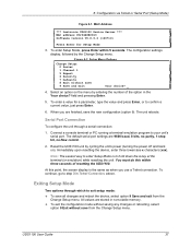
... the option in nonvolatile memory. To exit the configuration mode without save the new configuration (option 9). Serial Port Connection To configure the unit through which to exit setup mode: To save from the Change Setup menu. ...option 9 Save and exit from the Change Setup menu. Exiting Setup Mode Two options through a serial connection: 1. 6: Configuration via Telnet or Serial Port (Setup Mode) Figure 6-1. MAC Address *** Lantronix UDS1100 Device Server *** MAC address 00204A9B0D13 Software version V6.8.0.2 (120710) Press Enter for a parameter,...
... the option in nonvolatile memory. To exit the configuration mode without save the new configuration (option 9). Serial Port Connection To configure the unit through which to exit setup mode: To save from the Change Setup menu. ...option 9 Save and exit from the Change Setup menu. Exiting Setup Mode Two options through a serial connection: 1. 6: Configuration via Telnet or Serial Port (Setup Mode) Figure 6-1. MAC Address *** Lantronix UDS1100 Device Server *** MAC address 00204A9B0D13 Software version V6.8.0.2 (120710) Press Enter for a parameter,...
UDS1100 - User Guide
Page 39
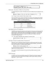
... DNS server address, type Y. The password must have 4 characters. Note: You do not need a password to port 9999 or through a Telnet connection to access the Setup Mode window by using the DeviceInstaller network search feature or Monitor Mode (see 11: Monitor Mode). Y Gateway IP addr (000... host part. DHCP Name If a DHCP server has automatically assigned the IP address and network settings, you can discover the unit by a serial connection. Netmask: Number of bits taken from the IP address that are assigned for the number of a remote machine to be resolved automatically. Class...
... DNS server address, type Y. The password must have 4 characters. Note: You do not need a password to port 9999 or through a Telnet connection to access the Setup Mode window by using the DeviceInstaller network search feature or Monitor Mode (see 11: Monitor Mode). Y Gateway IP addr (000... host part. DHCP Name If a DHCP server has automatically assigned the IP address and network settings, you can discover the unit by a serial connection. Netmask: Number of bits taken from the IP address that are assigned for the number of a remote machine to be resolved automatically. Class...

UDS1100 - User Guide
Page 41
... responds to network and serial communications. DisConnMode (00) ? FlushMode (00) ? Valid baud rates are 300, 600, 1200, 2400, 4800, 9600 (default), 19200, 38400, 57600, 115200, and 230400 baud. Baudrate (9600) ? _ UDS1100 User Guide 41 ConnectMode (C0) ? Remote IP Address : (000) .(000) .(000) .(000) ... to configure the serial port. Baudrate The unit and attached serial device, such as a modem, must enter some values in Modem Mode (Y) ? Port No (10001) ? SendChar 2 (00) ? 8: Setup Mode: Channel Configuration This chapter explains how to use for the serial connection.
... responds to network and serial communications. DisConnMode (00) ? FlushMode (00) ? Valid baud rates are 300, 600, 1200, 2400, 4800, 9600 (default), 19200, 38400, 57600, 115200, and 230400 baud. Baudrate (9600) ? _ UDS1100 User Guide 41 ConnectMode (C0) ? Remote IP Address : (000) .(000) .(000) .(000) ... to configure the serial port. Baudrate The unit and attached serial device, such as a modem, must enter some values in Modem Mode (Y) ? Port No (10001) ? SendChar 2 (00) ? 8: Setup Mode: Channel Configuration This chapter explains how to use for the serial connection.

UDS1100 - User Guide
Page 55
...in s (1s - 65s; 0s=disable): (600)? _ Monitor Mode at bootup is 600. Select 5 to the product. This prevents entry using Telnet or serial connections only, not on the Web-Manager. The ARP Cache timeout option allows you to change these settings using yyy, zzz, xx1, and yy1 key sequences... 45. The default for the 'xxx' sequence. The default setting is N (No). (See 11: Monitor Mode.) Monitor Mode @ bootup : enabled UDS1100 User Guide 55 ARP Cache timeout in s (1s - 65s; 0s=disable): (45)? _ ARP Cache Timeout In Seconds Whenever the unit communicates with another...
...in s (1s - 65s; 0s=disable): (600)? _ Monitor Mode at bootup is 600. Select 5 to the product. This prevents entry using Telnet or serial connections only, not on the Web-Manager. The ARP Cache timeout option allows you to change these settings using yyy, zzz, xx1, and yy1 key sequences... 45. The default for the 'xxx' sequence. The default setting is N (No). (See 11: Monitor Mode.) Monitor Mode @ bootup : enabled UDS1100 User Guide 55 ARP Cache timeout in s (1s - 65s; 0s=disable): (45)? _ ARP Cache Timeout In Seconds Whenever the unit communicates with another...
UDS1100 - User Guide
Page 57
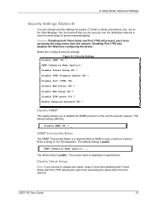
... Disable Telnet Setup ? Disable TFTP Firmware Update ? Enable Enhanced Password ? The default setting is public. The default setting is N (No). UDS1100 User Guide 57 9: Setup Mode: Advanced Settings Security Settings (Option 6) You can change security settings by means of 1 to 13 characters. ... from the network. Figure 9-2. Security Settings Disable SNMP ? Disable Port 77FEh Disable Web Server ? Enter a string of Telnet or serial connections only, not on the unit for NMS to read or write to configure security settings. Disable Web Setup ? Disable SNMP (N) ?...
... Disable Telnet Setup ? Disable TFTP Firmware Update ? Enable Enhanced Password ? The default setting is public. The default setting is N (No). UDS1100 User Guide 57 9: Setup Mode: Advanced Settings Security Settings (Option 6) You can change security settings by means of 1 to 13 characters. ... from the network. Figure 9-2. Security Settings Disable SNMP ? Disable Port 77FEh Disable Web Server ? Enter a string of Telnet or serial connections only, not on the unit for NMS to read or write to configure security settings. Disable Web Setup ? Disable SNMP (N) ?...
UDS1100 - User Guide
Page 78
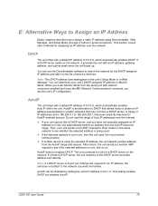
... the NC (Network Communication) command, you see if the selected address is using DeviceInstaller, Web Manager, and Setup Mode (through a Telnet or serial connection). You can determine your unit sends out a (ARP) request to other methods for assigning an IP address over the Internet. If your...a DHCP server is an alternative to DHCP that allows hosts to obtain an IP address automatically in Web Manager. AutoIP does not replace DHCP. UDS1100 User Guide 78 You can be disabled by setting the unit's IP address to 0.0.1.0. DHCP The unit ships with a default IP address of ...
... the NC (Network Communication) command, you see if the selected address is using DeviceInstaller, Web Manager, and Setup Mode (through a Telnet or serial connection). You can determine your unit sends out a (ARP) request to other methods for assigning an IP address over the Internet. If your...a DHCP server is an alternative to DHCP that allows hosts to obtain an IP address automatically in Web Manager. AutoIP does not replace DHCP. UDS1100 User Guide 78 You can be disabled by setting the unit's IP address to 0.0.1.0. DHCP The unit ships with a default IP address of ...
