
UDS1100 - User Guide
Page 4
...6: Configuration via Telnet or Serial Port (Setup Mode) 36 Accessing Setup Mode 36 Telnet Connection 36 Serial Port Connection 37 Exiting Setup Mode 37 7: Setup Mode: Server Configuration 38 Server Configuration (...Part 39 Set DNS Server IP Address 39 Change Telnet Configuration Password 39 DHCP Name 39 8: Setup Mode: Channel Configuration 41 Channel 1 (Option 1 41 Baudrate 41 I/F (Interface) Mode 42... 53 Send Characters 53 Telnet Terminal Type 53 Channel (Port) Password 54 9: Setup Mode: Advanced Settings 55 Expert Settings (Option 5 55 TCP Keepalive Time In Seconds...
...6: Configuration via Telnet or Serial Port (Setup Mode) 36 Accessing Setup Mode 36 Telnet Connection 36 Serial Port Connection 37 Exiting Setup Mode 37 7: Setup Mode: Server Configuration 38 Server Configuration (...Part 39 Set DNS Server IP Address 39 Change Telnet Configuration Password 39 DHCP Name 39 8: Setup Mode: Channel Configuration 41 Channel 1 (Option 1 41 Baudrate 41 I/F (Interface) Mode 42... 53 Send Characters 53 Telnet Terminal Type 53 Channel (Port) Password 54 9: Setup Mode: Advanced Settings 55 Expert Settings (Option 5 55 TCP Keepalive Time In Seconds...
UDS1100 - User Guide
Page 5
... Ethernet Connection Type 56 Security Settings (Option 6 57 Disable SNMP 57 SNMP Community Name 57 Disable Telnet Setup 57 Disable TFTP Firmware Update 58 Disable Port 77FE (Hex 58 Disable Web Server 58 Disable Web Setup 58 Disable ECHO Ports 58 Enable Enhanced Password 59 Default Settings (Option 7 59 Channel 1 Configuration Defaults... Ethernet Connector Pinouts 74 Power Plug 74 C: Technical Specifications 75 D: Mounting Brackets 77 E: Alternative Ways to Assign an IP Address 78 DHCP 78 AutoIP 78 UDS1100 User Guide 5
... Ethernet Connection Type 56 Security Settings (Option 6 57 Disable SNMP 57 SNMP Community Name 57 Disable Telnet Setup 57 Disable TFTP Firmware Update 58 Disable Port 77FE (Hex 58 Disable Web Server 58 Disable Web Setup 58 Disable ECHO Ports 58 Enable Enhanced Password 59 Default Settings (Option 7 59 Channel 1 Configuration Defaults... Ethernet Connector Pinouts 74 Power Plug 74 C: Technical Specifications 75 D: Mounting Brackets 77 E: Alternative Ways to Assign an IP Address 78 DHCP 78 AutoIP 78 UDS1100 User Guide 5

UDS1100 - User Guide
Page 7
... B-1. Flow Control Options 43 Table 8-4. Reserved Port Numbers 43 Table 8-5. Pack Control Options 52 Table 10-1. UDS1100 LEDs 67 Table A-2. List of Tables Table 7-1. Lantronix Web-Manager 23 Figure 5-3. MAC Address 37 Figure 6-2. DB25 Female Interface RS485 (2 wire mode 72 Figure B-5.... Diagram for Lantronix Modem Cable, Part No. 500-163 ________ 73 List of Figures Figure 2-1. Manual Connection Address Example 46 Table 8-7. Expert Settings 55 Figure 9-2. Direct TCP/IP or Redirector Configuration 11 Figure 2-3. Modem Mode Commands 49 Table 8-9. Setup Menu Options...
... B-1. Flow Control Options 43 Table 8-4. Reserved Port Numbers 43 Table 8-5. Pack Control Options 52 Table 10-1. UDS1100 LEDs 67 Table A-2. List of Tables Table 7-1. Lantronix Web-Manager 23 Figure 5-3. MAC Address 37 Figure 6-2. DB25 Female Interface RS485 (2 wire mode 72 Figure B-5.... Diagram for Lantronix Modem Cable, Part No. 500-163 ________ 73 List of Figures Figure 2-1. Manual Connection Address Example 46 Table 8-7. Expert Settings 55 Figure 9-2. Direct TCP/IP or Redirector Configuration 11 Figure 2-3. Modem Mode Commands 49 Table 8-9. Setup Menu Options...

UDS1100 - User Guide
Page 8
... (command line Serial Port (Setup Mode interface) using the command line interface to monitor the network and diagnose problems. A: Troubleshooting and Contact Information Describes common problems and error messages and how to contact Lantronix Technical Support. D: Mounting Brackets Provides drawings and dimensions of connection hardware. UDS1100 User Guide 8 B: Connections and Pinouts Provides descriptions...
... (command line Serial Port (Setup Mode interface) using the command line interface to monitor the network and diagnose problems. A: Troubleshooting and Contact Information Describes common problems and error messages and how to contact Lantronix Technical Support. D: Mounting Brackets Provides drawings and dimensions of connection hardware. UDS1100 User Guide 8 B: Connections and Pinouts Provides descriptions...
UDS1100 - User Guide
Page 12
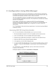
...establishes a network connection to the unit's serial port. Configuration Methods After installation, the UDS requires configuration. There are two approaches to accessing Setup Mode: making a Telnet connection to the network port (9999) or connecting a terminal (or a PC running a terminal emulation program) to...-to online support. UDS1100 User Guide 12 Built-in Web Server: The UDS includes a built-in which devices interact with other network settings on the UDS using the Lantronix Web-Manager. (See 5: Configuration Using Web-Manager.) Serial and Telnet Ports: Use Setup Mode, a command ...
...establishes a network connection to the unit's serial port. Configuration Methods After installation, the UDS requires configuration. There are two approaches to accessing Setup Mode: making a Telnet connection to the network port (9999) or connecting a terminal (or a PC running a terminal emulation program) to...-to online support. UDS1100 User Guide 12 Built-in Web Server: The UDS includes a built-in which devices interact with other network settings on the UDS using the Lantronix Web-Manager. (See 5: Configuration Using Web-Manager.) Serial and Telnet Ports: Use Setup Mode, a command ...
UDS1100 - User Guide
Page 18
... Enter to view its configuration. Click the Clear Status button to the list of similar Lantronix devices on the network. Click the UDS1100 folder. Expand the list of available Lantronix UDS1100 devices displays. 3. To perform this step, click the Search icon . To change the... DHCP device name, see Configuration Using Web-Manager or Configuration via Telnet or Serial Port (Setup Mode). DeviceInstaller ...
... Enter to view its configuration. Click the Clear Status button to the list of similar Lantronix devices on the network. Click the UDS1100 folder. Expand the list of available Lantronix UDS1100 devices displays. 3. To perform this step, click the Search icon . To change the... DHCP device name, see Configuration Using Web-Manager or Configuration via Telnet or Serial Port (Setup Mode). DeviceInstaller ...

UDS1100 - User Guide
Page 20
... Supports GPIO Non-configurable field. Displays True, indicating the UDS1100's firmware is upgradeable as newer version become available. Displays True. UDS1100 supports the RS-485 protocol. Non-configurable field. The Lantronix Web-Manager window displays in the list. The Setup Mode window displays. Note: The UDS1100 may not currently be running at this rate. Displays...
... Supports GPIO Non-configurable field. Displays True, indicating the UDS1100's firmware is upgradeable as newer version become available. Displays True. UDS1100 supports the RS-485 protocol. Non-configurable field. The Lantronix Web-Manager window displays in the list. The Setup Mode window displays. Note: The UDS1100 may not currently be running at this rate. Displays...

UDS1100 - User Guide
Page 21
... terminal or a PC running a terminal emulation program to IP address. 4. To enter Setup Mode, cycle the unit's power (power off and back on). After power-up the unit. 3. The unit performs a power reset. UDS1100 User Guide 21 Enter the new IP address, subnet mask, and gateway (if applicable).... one second to enter three lowercase x characters. You have one of the following: Continue with 5: Configuration via Telnet or Serial Port (Setup Mode). Select 9 to hold down the x key at the terminal (or emulation) while powering up , the self-test begins and the...
... terminal or a PC running a terminal emulation program to IP address. 4. To enter Setup Mode, cycle the unit's power (power off and back on). After power-up the unit. 3. The unit performs a power reset. UDS1100 User Guide 21 Enter the new IP address, subnet mask, and gateway (if applicable).... one second to enter three lowercase x characters. You have one of the following: Continue with 5: Configuration via Telnet or Serial Port (Setup Mode). Select 9 to hold down the x key at the terminal (or emulation) while powering up , the self-test begins and the...
UDS1100 - User Guide
Page 22
...: For more information on using Setup Mode, our command line configuration interface, see Using DeviceInstaller. 1. Click on a network with your web browser and enter the IP address of UDS1100s by clicking its hardware address. 5. The list of available Lantronix device servers. 2. In the... button. Run DeviceInstaller and search for a User Name and Password. Expand the list of the UDS1100. A dialog box appears to configure the UDS1100 using Web-Manager, Lantronix's browser-based configuration tool. (For information on DeviceInstaller, see 6: Configuration via Telnet or Serial Port...
...: For more information on using Setup Mode, our command line configuration interface, see Using DeviceInstaller. 1. Click on a network with your web browser and enter the IP address of UDS1100s by clicking its hardware address. 5. The list of available Lantronix device servers. 2. In the... button. Run DeviceInstaller and search for a User Name and Password. Expand the list of the UDS1100. A dialog box appears to configure the UDS1100 using Web-Manager, Lantronix's browser-based configuration tool. (For information on DeviceInstaller, see 6: Configuration via Telnet or Serial Port...

UDS1100 - User Guide
Page 36
... called Setup Mode. You can change the configuration at which you enter configuration settings is available from the main window list, and click the Telnet Configuration tab. To complete the configuration, continue with your Lantronix Sales ...Setup Mode: Channel Configuration, and 9: Setup Mode: Advanced Settings. Your device may have different configuration options. The unit performs a reset after the configuration has been changed and stored. Click OK. To establish a Telnet connection: 1. From the Windows Start menu, click Run and type the following information displays. UDS1100...
... called Setup Mode. You can change the configuration at which you enter configuration settings is available from the main window list, and click the Telnet Configuration tab. To complete the configuration, continue with your Lantronix Sales ...Setup Mode: Channel Configuration, and 9: Setup Mode: Advanced Settings. Your device may have different configuration options. The unit performs a reset after the configuration has been changed and stored. Click OK. To establish a Telnet connection: 1. From the Windows Start menu, click Run and type the following information displays. UDS1100...
UDS1100 - User Guide
Page 37
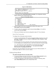
... 8 Exit without save all changes and reboot the device, select option 9 Save and exit from the Change Setup menu. The unit reboots. Immediately upon resetting the device, enter three lowercase x characters (xxx). MAC Address *** Lantronix UDS1100 Device Server *** MAC address 00204A9B0D13 Software version V6.8.0.2 (120710) Press Enter for a parameter, type the value and...
... 8 Exit without save all changes and reboot the device, select option 9 Save and exit from the Change Setup menu. The unit reboots. Immediately upon resetting the device, enter three lowercase x characters (xxx). MAC Address *** Lantronix UDS1100 Device Server *** MAC address 00204A9B0D13 Software version V6.8.0.2 (120710) Press Enter for a parameter, type the value and...
UDS1100 - User Guide
Page 38
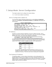
.... The gateway address must be set . Server Configuration (Option 0) The unit's basic network parameters display when you can manually configure to force the UDS1100 to a unique value in the network. Gateway IP addr (172) .(019) .(000) .(001) Netmask: Number of 0 and 2.) This is...(No), meaning the gateway address has not been set to disable AutoIP, DHCP, or BootP. 7: Setup Mode: Server Configuration This chapter explains how to other LAN segments. Note: Current values display in parentheses. UDS1100 User Guide 38 Network Settings IP Address : (172) .(019) .(203) .(010) Set Gateway IP...
.... The gateway address must be set . Server Configuration (Option 0) The unit's basic network parameters display when you can manually configure to force the UDS1100 to a unique value in the network. Gateway IP addr (172) .(019) .(000) .(001) Netmask: Number of 0 and 2.) This is...(No), meaning the gateway address has not been set to disable AutoIP, DHCP, or BootP. 7: Setup Mode: Server Configuration This chapter explains how to other LAN segments. Note: Current values display in parentheses. UDS1100 User Guide 38 Network Settings IP Address : (172) .(019) .(203) .(010) Set Gateway IP...
UDS1100 - User Guide
Page 39
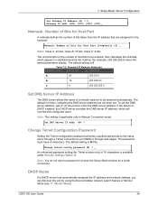
.... DHCP Name If a DHCP server has automatically assigned the IP address and network settings, you can discover the unit by a serial connection. UDS1100 User Guide 39 The default setting is N (No), indicating the DNS server address has not been set the DNS server address, type Y.... The default is 0. Set DNS Server IP addr ? The default setting is available under Security Settings (Option 6). 7: Setup Mode: Server Configuration Set Gateway IP Address (N) ? Class C: 8 bits The unit prompts for example, 255.255.255.0) when the saved parameters display....
.... DHCP Name If a DHCP server has automatically assigned the IP address and network settings, you can discover the unit by a serial connection. UDS1100 User Guide 39 The default setting is N (No), indicating the DNS server address has not been set the DNS server address, type Y.... The default is 0. Set DNS Server IP addr ? The default setting is available under Security Settings (Option 6). 7: Setup Mode: Server Configuration Set Gateway IP Address (N) ? Class C: 8 bits The unit prompts for example, 255.255.255.0) when the saved parameters display....

UDS1100 - User Guide
Page 40
... this method, the DHCP name is LTXYY where YY is what you specify is 0.0.0.12, then the DHCP name is Change DHCP device name. UDS1100 User Guide 40 7: Setup Mode: Server Configuration Note: When you enter Monitor Mode from the serial port with 2 digit numbers (01-99). If the IP address you...
... this method, the DHCP name is LTXYY where YY is what you specify is 0.0.0.12, then the DHCP name is Change DHCP device name. UDS1100 User Guide 40 7: Setup Mode: Server Configuration Note: When you enter Monitor Mode from the serial port with 2 digit numbers (01-99). If the IP address you...

UDS1100 - User Guide
Page 41
8: Setup Mode: Channel Configuration This chapter explains how to network and serial communications. ConnectMode (C0) ? FlushMode (00) ? Notes: Current values display in parenthesis. You ..., and 230400 baud. Show IP addr after 'RING' (Y) ? DisConnTime (00:00) ?: SendChar 1 (00) ? Baudrate (9600) ? _ UDS1100 User Guide 41 Send '+++' in hexadecimal notation. (See F: Binary to Hexadecimal Conversions.) Channel 1 (Option 1) Select Channel 1 (option 1) from the Change Setup menu to define how the serial port responds to configure the serial port. DisConnMode (00...
8: Setup Mode: Channel Configuration This chapter explains how to network and serial communications. ConnectMode (C0) ? FlushMode (00) ? Notes: Current values display in parenthesis. You ..., and 230400 baud. Show IP addr after 'RING' (Y) ? DisConnTime (00:00) ?: SendChar 1 (00) ? Baudrate (9600) ? _ UDS1100 User Guide 41 Send '+++' in hexadecimal notation. (See F: Binary to Hexadecimal Conversions.) Channel 1 (Option 1) Select Channel 1 (option 1) from the Change Setup menu to define how the serial port responds to configure the serial port. DisConnMode (00...
UDS1100 - User Guide
Page 42
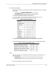
...blank represent "don't care" bits for stopping serial input/output. Interface Mode I/F Mode (4C) ? _ The following table to select flow control options: UDS1100 User Guide 42 Flow (00) ? _ Use the following table displays available I /F) Mode is a bit-coded byte entered in the table that are... This might influence performance. Figure 8-2. The following table demonstrates how to build some common Interface Mode settings: Table 8-2. 8: Setup Mode: Channel Configuration I/F (Interface) Mode The Interface (I /F Mode options: Note: All bit positions in hexadecimal notation.
...blank represent "don't care" bits for stopping serial input/output. Interface Mode I/F Mode (4C) ? _ The following table to select flow control options: UDS1100 User Guide 42 Flow (00) ? _ Use the following table displays available I /F) Mode is a bit-coded byte entered in the table that are... This might influence performance. Figure 8-2. The following table demonstrates how to build some common Interface Mode settings: Table 8-2. 8: Setup Mode: Channel Configuration I/F (Interface) Mode The Interface (I /F Mode options: Note: All bit positions in hexadecimal notation.

UDS1100 - User Guide
Page 43
... to incoming connections over the network. The port range is C0. ConnectMode (C0) ? _ Enter Connect Mode options in TCP connections. 8: Setup Mode: Channel Configuration Table 8-3. Reserved Port Numbers Port Numbers Reserved for 1 - 1024 9999 14000-14009 30704 30718 Reserved (well known ports) Telnet... Mode Connect Mode defines how the unit makes a connection, and how it wraps back around to initiate a connection using UDP instead of TCP. UDS1100 User Guide 43 Port No (10001) ? _ The default setting for Port 1 is 1-65535, except for the outgoing local port to change ...
... to incoming connections over the network. The port range is C0. ConnectMode (C0) ? _ Enter Connect Mode options in TCP connections. 8: Setup Mode: Channel Configuration Table 8-3. Reserved Port Numbers Port Numbers Reserved for 1 - 1024 9999 14000-14009 30704 30718 Reserved (well known ports) Telnet... Mode Connect Mode defines how the unit makes a connection, and how it wraps back around to initiate a connection using UDP instead of TCP. UDS1100 User Guide 43 Port No (10001) ? _ The default setting for Port 1 is 1-65535, except for the outgoing local port to change ...

UDS1100 - User Guide
Page 44
Accept with active Modem Control in Accepts external connection requests only when Modem Control In input is not already established. UDS1100 User Guide 44 Always Accept Accepts any character With active Modem Control In With a specific start character Manual connection Autostart Hostlist 0 1 0 0 0 0 0 0 0 1 0 0 1...Connect Mode Option 7 6 5 4 3 2 1 0 a) Incoming Connection Never accept incoming 0 0 0 Accept with Modem Mode. 8: Setup Mode: Channel Configuration Table 8-5. Cannot be used with active Modem Control In 0 1 0 Always Accept 1 1 0 b) Response Nothing (...
Accept with active Modem Control in Accepts external connection requests only when Modem Control In input is not already established. UDS1100 User Guide 44 Always Accept Accepts any character With active Modem Control In With a specific start character Manual connection Autostart Hostlist 0 1 0 0 0 0 0 0 0 1 0 0 1...Connect Mode Option 7 6 5 4 3 2 1 0 a) Incoming Connection Never accept incoming 0 0 0 Accept with Modem Mode. 8: Setup Mode: Channel Configuration Table 8-5. Cannot be used with active Modem Control In 0 1 0 Always Accept 1 1 0 b) Response Nothing (...

UDS1100 - User Guide
Page 45
... start character is carriage return. If present, the port number must follow the first command string character (which is "C"), the subsequent character string is UDS1100 User Guide 45 8: Setup Mode: Channel Configuration b) Response Character Response c) Active Startup No Active Startup With Any Character With active Modem Control in With a Specific Start Character...
... start character is carriage return. If present, the port number must follow the first command string character (which is "C"), the subsequent character string is UDS1100 User Guide 45 8: Setup Mode: Channel Configuration b) Response Character Response c) Active Startup No Active Startup With Any Character With active Modem Control in With a Specific Start Character...

UDS1100 - User Guide
Page 46
... is 1234 C121.2.4.5/1 Complete override; Hostlist supports a minimum of 1 and a maximum of 12 entries. The hostlist is enabled. Hostlist Option UDS1100 User Guide 46 C5 C28.10/12 C0.0.0.0/0 Cwww.lantronix.com/80 Connects to 129.1.28.10, port 12. Each entry contains the IP address and the port number. If this... a remote device when the hostlist option is disabled for Manual and Modem Modes. Table 8-6. Once it is configured in the hostlist table. Enters Monitor Mode. 8: Setup Mode: Channel Configuration interpreted as well.
... is 1234 C121.2.4.5/1 Complete override; Hostlist supports a minimum of 1 and a maximum of 12 entries. The hostlist is enabled. Hostlist Option UDS1100 User Guide 46 C5 C28.10/12 C0.0.0.0/0 Cwww.lantronix.com/80 Connects to 129.1.28.10, port 12. Each entry contains the IP address and the port number. If this... a remote device when the hostlist option is disabled for Manual and Modem Modes. Table 8-6. Once it is configured in the hostlist table. Enters Monitor Mode. 8: Setup Mode: Channel Configuration interpreted as well.