
WiPort - Data Sheet
Page 3
... 1 2 3 4 5 6 7 8 9 10 11 12 13 14 15 16 17 18 19 20 WiPort Pin Function 3.3V Power 3.3V Power RTS0 TXD0 RXD0 Configurable Pin 2 Configurable Pin 3 CTS0 Configurable Pin 10 Configurable Pin 8 Signal Ground Signal Ground Reset In Configurable Pin 0 RTS1 TXD1 RXD1 Configurable Pin 9 Configurable Pin 4 CTS1 Pin Number 21... 22 23 24 25 26 27 28 29 30 31 32 33 34 35 36 37 38 39 40 WiPort Pin Function Reserved Reserved Signal Ground Signal Ground...
... 1 2 3 4 5 6 7 8 9 10 11 12 13 14 15 16 17 18 19 20 WiPort Pin Function 3.3V Power 3.3V Power RTS0 TXD0 RXD0 Configurable Pin 2 Configurable Pin 3 CTS0 Configurable Pin 10 Configurable Pin 8 Signal Ground Signal Ground Reset In Configurable Pin 0 RTS1 TXD1 RXD1 Configurable Pin 9 Configurable Pin 4 CTS1 Pin Number 21... 22 23 24 25 26 27 28 29 30 31 32 33 34 35 36 37 38 39 40 WiPort Pin Function Reserved Reserved Signal Ground Signal Ground...

WiPort - Data Sheet
Page 5
... Power Consumption 1300mW 950mW 580mW 300mW 750mW WiPort b/g Data Sheet - WiPort Technical Data Category CPU, Memory Firmware Reset Circuit Serial Interface Serial Line Formats Modem Control... Flow Control Network Interface Protocols Supported Media Access Control Frequency Range Range Modulation Techniques Transmit Output Power Peak Supply Current at 3.3V Management Security Internal Web Server Weight Material Temperature Warranty Included Software Description Lantronix...
... Power Consumption 1300mW 950mW 580mW 300mW 750mW WiPort b/g Data Sheet - WiPort Technical Data Category CPU, Memory Firmware Reset Circuit Serial Interface Serial Line Formats Modem Control... Flow Control Network Interface Protocols Supported Media Access Control Frequency Range Range Modulation Techniques Transmit Output Power Peak Supply Current at 3.3V Management Security Internal Web Server Weight Material Temperature Warranty Included Software Description Lantronix...

WiPort - User Guide
Page 17
... and search for the list of available Lantronix device servers. 2. By default, no username and password are configured. To open the Web-Manager in the current DeviceInstaller window, click Go. Note: Alternatively, access the WiPort's Web-Manager if it is stored in... The unit performs a reset after the configuration is retained without power. To view the WiPort's Web-Manager in a web browser, click Use External Browser. 4: Configuration Using Web-Manager This chapter describes how to configure the WiPort using Web-Manager, Lantronix's browser-based configuration tool...
... and search for the list of available Lantronix device servers. 2. By default, no username and password are configured. To open the Web-Manager in the current DeviceInstaller window, click Go. Note: Alternatively, access the WiPort's Web-Manager if it is stored in... The unit performs a reset after the configuration is retained without power. To view the WiPort's Web-Manager in a web browser, click Use External Browser. 4: Configuration Using Web-Manager This chapter describes how to configure the WiPort using Web-Manager, Lantronix's browser-based configuration tool...

WiPort - User Guide
Page 38
... to factory defaults. Indicates errors and configurations. Asserting during bootup for at least seven seconds resets the configuration to cancel. For details, see Default Settings on the device. Usable as a half/full duplex selector. Apply Settings 1. WiPort User Guide 38 In addition, the wired network becomes the default interface. Used when network...
... to factory defaults. Indicates errors and configurations. Asserting during bootup for at least seven seconds resets the configuration to cancel. For details, see Default Settings on the device. Usable as a half/full duplex selector. Apply Settings 1. WiPort User Guide 38 In addition, the wired network becomes the default interface. Used when network...
WiPort - User Guide
Page 39
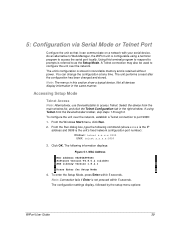
... typical device. If using a terminal program to access Telnet. You can communicate on a network with your serial device. The unit performs a reset after the configuration has been changed and stored. Select the device from the DeviceInstaller toolbar, skip steps 1 through 3. From the Run dialog box,...or Telnet Port Configure the unit so that it can change the configuration at any time. As an alternative to Web-Manager, the WiPort unit is not pressed within 5 seconds. Accessing Setup Mode Telnet Access Note: Alternatively, use DeviceInstaller to access the serial port locally....
... typical device. If using a terminal program to access Telnet. You can communicate on a network with your serial device. The unit performs a reset after the configuration has been changed and stored. Select the device from the DeviceInstaller toolbar, skip steps 1 through 3. From the Run dialog box,...or Telnet Port Configure the unit so that it can change the configuration at any time. As an alternative to Web-Manager, the WiPort unit is not pressed within 5 seconds. Accessing Setup Mode Telnet Access Note: Alternatively, use DeviceInstaller to access the serial port locally....
WiPort - User Guide
Page 40
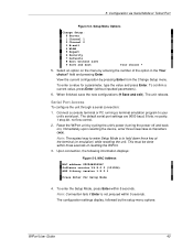
... seconds of the option in the Your choice? Upon connection, the following information displays: Figure 5-3. Serial Port Access To configure the unit through a serial connection: 1. Reset the WiPort unit by cycling the unit's power (turning the power off and back on the menu by entering the number of... resetting the WiPort. 3. The configuration settings display, followed by pressing Enter from the Change Setup menu. Note: The easiest way to enter Setup Mode is not pressed within 5 ...
... seconds of the option in the Your choice? Upon connection, the following information displays: Figure 5-3. Serial Port Access To configure the unit through a serial connection: 1. Reset the WiPort unit by cycling the unit's power (turning the power off and back on the menu by entering the number of... resetting the WiPort. 3. The configuration settings display, followed by pressing Enter from the Change Setup menu. Note: The easiest way to enter Setup Mode is not pressed within 5 ...

WiPort - User Guide
Page 68
...address, netmask, wireless enable, infrastructure or ad hoc setting, and wireless security settings remain unchanged. Note: To reset network settings to query or set the eleven WiPort configurable pins when they are listed below. no flow control) 10001 C0 (always accept incoming connection; The ...Y (Yes) option disables the GPIO control interface. Default Settings Select 7 Defaults from the Change Setup menu to reset the unit's Channel 1 ...
...address, netmask, wireless enable, infrastructure or ad hoc setting, and wireless security settings remain unchanged. Note: To reset network settings to query or set the eleven WiPort configurable pins when they are listed below. no flow control) 10001 C0 (always accept incoming connection; The ...Y (Yes) option disables the GPIO control interface. Default Settings Select 7 Defaults from the Change Setup menu to reset the unit's Channel 1 ...

WiPort - User Guide
Page 69
... No Connect Mode Hostlist Retry Counter Hostlist Retry Timeout Send Character All other WLAN settings, use one of the "Reset to Defaults" Configurable Pin Settings. WiPort User Guide 69 no flow control) 10002 C0 (always accept incoming connection; For more information on Configurable Pins, ...see Configurable Pins on page 80. To reset the other parameters WLAN Settings Topology Network Name Channel Security TX Data ...
... No Connect Mode Hostlist Retry Counter Hostlist Retry Timeout Send Character All other WLAN settings, use one of the "Reset to Defaults" Configurable Pin Settings. WiPort User Guide 69 no flow control) 10002 C0 (always accept incoming connection; For more information on Configurable Pins, ...see Configurable Pins on page 80. To reset the other parameters WLAN Settings Topology Network Name Channel Security TX Data ...

WiPort - User Guide
Page 77
...mask, and DNS server. G0, G1, ....,Ge, Gf Get configuration from memory page Gets a memory page of unit from the device. RS Reset Resets the unit. GM Get MAC address Shows the unit's 6-byte MAC. Reports any stations found, including BSSID, SSID, and RSSI. If SA ...memory page Sets a memory page of the commands are given in Intel Hex format. NS Network Status Reports the network interfaces' statuses. WiPort User Guide 77 WS Wireless Status Displays wireless module status that includes packets received, transmitted, and dropped. AT ARP Table Shows the ...
...mask, and DNS server. G0, G1, ....,Ge, Gf Get configuration from memory page Gets a memory page of unit from the device. RS Reset Resets the unit. GM Get MAC address Shows the unit's 6-byte MAC. Reports any stations found, including BSSID, SSID, and RSSI. If SA ...memory page Sets a memory page of the commands are given in Intel Hex format. NS Network Status Reports the network interfaces' statuses. WiPort User Guide 77 WS Wireless Status Displays wireless module status that includes packets received, transmitted, and dropped. AT ARP Table Shows the ...

WiPort - User Guide
Page 79
... up the wired host connected to the WiPort's wired interface for configuration. 1. Reset the WiPort. 3. Use a utility to query the WiPort. 2. WiPort User Guide 79 This requires the modification of the wired host's IP address as well as necessary. This utility must use the Lantronix access protocol to locate the WiPort's MAC address and auto-IP address...
... up the wired host connected to the WiPort's wired interface for configuration. 1. Reset the WiPort. 3. Use a utility to query the WiPort. 2. WiPort User Guide 79 This requires the modification of the wired host's IP address as well as necessary. This utility must use the Lantronix access protocol to locate the WiPort's MAC address and auto-IP address...

WiPort - User Guide
Page 80
8: Wireless Bridging 6. Disconnect the wired device and reconnect the original wired host to configuring through the wired interface, connect a device through the serial port, see 5: Configuration via Serial Mode or Telnet Port on configuration through the WiPort's serial port. WiPort User Guide 80 Reset the WiPort. For more information on page 39. Method 3 As an alternative to the WiPort. 7.
8: Wireless Bridging 6. Disconnect the wired device and reconnect the original wired host to configuring through the wired interface, connect a device through the serial port, see 5: Configuration via Serial Mode or Telnet Port on configuration through the WiPort's serial port. WiPort User Guide 80 Reset the WiPort. For more information on page 39. Method 3 As an alternative to the WiPort. 7.

WiPort - User Guide
Page 81
... operation and Binary format. 4. Enter the full path of the unit being upgraded. 3. WiPort User Guide 81 Obtaining Firmware Obtain the most up-to-date firmware and release notes for ...release notes. Here are typical names for information about reloading firmware using anonymous FTP (ftp.lantronix.com). Firmware Files ROM File WPTxxx.ROM COB WPT_WNxxx.COB (Web-Manager) Please refer to...(the preferred way), via TFTP, or via TFTP or DeviceInstaller. The unit performs a power reset after the firmware has been loaded and stored. The other methods are several ways to the ...
... operation and Binary format. 4. Enter the full path of the unit being upgraded. 3. WiPort User Guide 81 Obtaining Firmware Obtain the most up-to-date firmware and release notes for ...release notes. Here are typical names for information about reloading firmware using anonymous FTP (ftp.lantronix.com). Firmware Files ROM File WPTxxx.ROM COB WPT_WNxxx.COB (Web-Manager) Please refer to...(the preferred way), via TFTP, or via TFTP or DeviceInstaller. The unit performs a power reset after the firmware has been loaded and stored. The other methods are several ways to the ...

WiPort - Integration Guide
Page 5
... Integration Guide 7 Additional Documentation 7 2: Description and Specifications 8 WiPort Overview 8 WiPort Block Diagram 9 PCB Interface 10 Mating Connector 11 Serial Input/Output 11 Sample Layouts for RS-485 Connectivity 13 WLAN Input/Output 14 Ethernet Input/Output 15 Power, Ground, and Reset 15 Absolute Maximum Ratings 15 Recommended Operating Conditions 16 Ethernet...23 General Control PLD 23 Configuration Switch Bank 23 Evaluation Board Layout 24 Evaluation Board Schematics 25 Compliance Information 29 Warranty 30 WiPort™ Integration Guide 5
... Integration Guide 7 Additional Documentation 7 2: Description and Specifications 8 WiPort Overview 8 WiPort Block Diagram 9 PCB Interface 10 Mating Connector 11 Serial Input/Output 11 Sample Layouts for RS-485 Connectivity 13 WLAN Input/Output 14 Ethernet Input/Output 15 Power, Ground, and Reset 15 Absolute Maximum Ratings 15 Recommended Operating Conditions 16 Ethernet...23 General Control PLD 23 Configuration Switch Bank 23 Evaluation Board Layout 24 Evaluation Board Schematics 25 Compliance Information 29 Warranty 30 WiPort™ Integration Guide 5

WiPort - Integration Guide
Page 6
... PCB Layout ...21 Figure 2-10. PCB Interface Signals ...10 Table 2-2. Channel 1 Connections ...12 Table 2-4. Configurable Pin Configurations 24 WiPort™ Integration Guide 6 Channel 2 RS-422/485 4-Wire Connections 12 Table 2-6. WLAN Signals ...14 Table 2-8. RS-232 Signals ...... 2-4. Bottom View ...20 Figure 2-8. Power, Ground, and Reset Pins 15 Table 2-10. List of Tables Table 2-1. WiPort Block Diagram ...9 Figure 2-2. Side Views ...19 Figure 2-6. Top View ...19 Figure 2-7. WiPort Evaluation Board Layout 24 Figure 3-2. Evaluation Board Schematics 25 List...
... PCB Layout ...21 Figure 2-10. PCB Interface Signals ...10 Table 2-2. Channel 1 Connections ...12 Table 2-4. Configurable Pin Configurations 24 WiPort™ Integration Guide 6 Channel 2 RS-422/485 4-Wire Connections 12 Table 2-6. WLAN Signals ...14 Table 2-8. RS-232 Signals ...... 2-4. Bottom View ...20 Figure 2-8. Power, Ground, and Reset Pins 15 Table 2-10. List of Tables Table 2-1. WiPort Block Diagram ...9 Figure 2-2. Side Views ...19 Figure 2-6. Top View ...19 Figure 2-7. WiPort Evaluation Board Layout 24 Figure 3-2. Evaluation Board Schematics 25 List...

WiPort - Integration Guide
Page 10
... output (logic level), serial port 0 Receive data input (logic level), serial port 0 Configurable pin Configurable pin. Minimum reset pulse width is low active. PCB Interface Signals WiPort Pin Function 3.3V Power 3.3V Power RTS0 TXD0 RXD0 CP2 CP3 CTS0 CP10 CP8 Signal Ground Signal Ground...TX+ Notes Supply input Supply input Request "to send" hardware flow control input (logic level), serial port 0 Configurable pin Configurable pin Resets the WiPort unit. Reset In is 2ms at IIL = -500 µA Configurable pin Request "to send" hardware flow control output (logic level), serial port ...
... output (logic level), serial port 0 Receive data input (logic level), serial port 0 Configurable pin Configurable pin. Minimum reset pulse width is low active. PCB Interface Signals WiPort Pin Function 3.3V Power 3.3V Power RTS0 TXD0 RXD0 CP2 CP3 CTS0 CP10 CP8 Signal Ground Signal Ground...TX+ Notes Supply input Supply input Request "to send" hardware flow control input (logic level), serial port 0 Configurable pin Configurable pin Resets the WiPort unit. Reset In is 2ms at IIL = -500 µA Configurable pin Request "to send" hardware flow control output (logic level), serial port ...

WiPort - Integration Guide
Page 15
...WLAN is 2ms at (800) 422-7055 (US only) or (949) 453-7198. Power, Ground, and Reset Table 2-9. Description and Specifications Note: If you have questions or concerns, please contact Lantronix Technical Support at IIL = -500uA Absolute Maximum Ratings Table 2-10. Ethernet Link LED 1 can be on ...WiPortB and Activity LED on when a link exists. Power, Ground, and Reset Pins Power Pin 1 Pin 2 Ground Pin 11 Pin 12 Pin 23 Pin 24 Reset Pin 13 Driving the Reset In line low resets the WiPort. Minimum reset pulse width is selectable for the creation of an Ethernet interface (instead of...
...WLAN is 2ms at (800) 422-7055 (US only) or (949) 453-7198. Power, Ground, and Reset Table 2-9. Description and Specifications Note: If you have questions or concerns, please contact Lantronix Technical Support at IIL = -500uA Absolute Maximum Ratings Table 2-10. Ethernet Link LED 1 can be on ...WiPortB and Activity LED on when a link exists. Power, Ground, and Reset Pins Power Pin 1 Pin 2 Ground Pin 11 Pin 12 Pin 23 Pin 24 Reset Pin 13 Driving the Reset In line low resets the WiPort. Minimum reset pulse width is selectable for the creation of an Ethernet interface (instead of...

WiPort - Integration Guide
Page 18
... CPU, Memory Firmware Reset Circuit Serial Interface Serial Line Formats Modem Control Flow Control Network Interface Protocols Supported Management Internal Web Server Distance Average Power Consumption (at 3.3V) Peak Supply Current (at 230 kbps.) 550 mW (High performance. Technical Specifications WiPort B Lantronix DSTni-EX 186 CPU..., 256 KB zero wait state SRAM 2048 KB Flash or 4096 KB Flash, 16 KB Boot ROM, 1024 KB SRAM Upgradeable via TFTP and serial port Reset In is 2 ms at 230 kbps.) 580...
... CPU, Memory Firmware Reset Circuit Serial Interface Serial Line Formats Modem Control Flow Control Network Interface Protocols Supported Management Internal Web Server Distance Average Power Consumption (at 3.3V) Peak Supply Current (at 230 kbps.) 550 mW (High performance. Technical Specifications WiPort B Lantronix DSTni-EX 186 CPU..., 256 KB zero wait state SRAM 2048 KB Flash or 4096 KB Flash, 16 KB Boot ROM, 1024 KB SRAM Upgradeable via TFTP and serial port Reset In is 2 ms at 230 kbps.) 580...

WiPort - Integration Guide
Page 25
I2C/CAN ETH PHY USB RF LED's INSTALLED WiPORT 3.3V UART0 UART1 STATUS LED's RESETI2C/CAN ETH PHY USB RF LED's PIGTAIL ANTENNA +3.3V LED POWER SUPPLY PWR SWITCH PWR CONN UART0 RS232 DB9 TXCVR UART1 RS232/485 DB9 TXCVR RESET SWITCH CPLD TXD0 ACTIVE LED RXD0 ACTIVE LED TXD1 ACTIVE LED RXD1 ACTIVE LED 3 STATUS LED's RJ-45 with MAGNETICS and 2 LED's 2 LED's WiPort™ Integration Guide 25 Evaluation Board Schematics UART0 WiPORT TEST HEADERS 2X10 - 2EA UART1 STATUS LED's RESET- Development Kit Evaluation Board Schematics Figure 3-2.
I2C/CAN ETH PHY USB RF LED's INSTALLED WiPORT 3.3V UART0 UART1 STATUS LED's RESETI2C/CAN ETH PHY USB RF LED's PIGTAIL ANTENNA +3.3V LED POWER SUPPLY PWR SWITCH PWR CONN UART0 RS232 DB9 TXCVR UART1 RS232/485 DB9 TXCVR RESET SWITCH CPLD TXD0 ACTIVE LED RXD0 ACTIVE LED TXD1 ACTIVE LED RXD1 ACTIVE LED 3 STATUS LED's RJ-45 with MAGNETICS and 2 LED's 2 LED's WiPort™ Integration Guide 25 Evaluation Board Schematics UART0 WiPORT TEST HEADERS 2X10 - 2EA UART1 STATUS LED's RESET- Development Kit Evaluation Board Schematics Figure 3-2.

WiPort - Integration Guide
Page 26
... - ACTIVE (Green) Right LED - LINK (Yellow) RJ-45, LU1T041C-43 3V3 1 C9 TP2 .01uF, HV 2 1 2 SHIELD C10 .01uF, HV 1 Development Kit 26 WiPort™ Integration Guide TXD0 CP2 CTS0 CP8 CP0 TXD1 CP9 CTS1 RESERVED RESERVED ELED1 TX+ TCT RX+ WLAN POW CP5 CP7 3V3_Wi 1 1 C53 C1 0.01uF... CP10 RTS1 RXD1 CP4 RESERVED RESERVED ELED2 TXRCT RXCP1 CP6 WLAN ACT TSM-120-01-T-DV Test Header for WiPort I/O MH1 1 MHOLE MH5 1 MHOLE MH2 1 MHOLE MH6 1 MHOLE MH3 1 MHOLE MH4 1 MHOLE RESET SWITCH SW1 2 1 4 3 EVO0PFC03M ELED2 ELED1 RSTIN# 182 R1 182 R2 TX+ TXTCT RX+ RCT RX- 3V3 ...
... - ACTIVE (Green) Right LED - LINK (Yellow) RJ-45, LU1T041C-43 3V3 1 C9 TP2 .01uF, HV 2 1 2 SHIELD C10 .01uF, HV 1 Development Kit 26 WiPort™ Integration Guide TXD0 CP2 CTS0 CP8 CP0 TXD1 CP9 CTS1 RESERVED RESERVED ELED1 TX+ TCT RX+ WLAN POW CP5 CP7 3V3_Wi 1 1 C53 C1 0.01uF... CP10 RTS1 RXD1 CP4 RESERVED RESERVED ELED2 TXRCT RXCP1 CP6 WLAN ACT TSM-120-01-T-DV Test Header for WiPort I/O MH1 1 MHOLE MH5 1 MHOLE MH2 1 MHOLE MH6 1 MHOLE MH3 1 MHOLE MH4 1 MHOLE RESET SWITCH SW1 2 1 4 3 EVO0PFC03M ELED2 ELED1 RSTIN# 182 R1 182 R2 TX+ TXTCT RX+ RCT RX- 3V3 ...

WiPort-485 - Data Sheet
Page 4
...Number 1 2 3 4 5 6 7 8 9 10 11 12 13 14 15 16 17 18 19 20 WiPort-485 Pin Function 3.3V Power 3.3V Power RTS0 TXD0 RXD0 Configurable Pin 2 Configurable Pin 3 CTS0 Configurable Pin 10 Configurable Pin 8 Signal Ground Signal Ground Reset In Configurable Pin 0 RTS1 TXD1 RXD1 Configurable Pin 9 Configurable Pin 4 CTS1 Pin Number... 21 22 23 24 25 26 27 28 29 30 31 32 33 34 35 36 37 38 39 40 WiPort-485 Pin Function Reserved Reserved Signal Ground Signal ...
...Number 1 2 3 4 5 6 7 8 9 10 11 12 13 14 15 16 17 18 19 20 WiPort-485 Pin Function 3.3V Power 3.3V Power RTS0 TXD0 RXD0 Configurable Pin 2 Configurable Pin 3 CTS0 Configurable Pin 10 Configurable Pin 8 Signal Ground Signal Ground Reset In Configurable Pin 0 RTS1 TXD1 RXD1 Configurable Pin 9 Configurable Pin 4 CTS1 Pin Number... 21 22 23 24 25 26 27 28 29 30 31 32 33 34 35 36 37 38 39 40 WiPort-485 Pin Function Reserved Reserved Signal Ground Signal ...

