
xPico - Integration Guide
Page 3
... successful communication. Note: With the purchase of the End Product (xPico Wi-Fi only) The label on the end product incorporating the xPico Wi-Fi module must be used on the final product (including the transmitter). Changes or modifications to this device not explicitly approved by Lantronix will not be met (for example certain laptop configurations, general...
... successful communication. Note: With the purchase of the End Product (xPico Wi-Fi only) The label on the end product incorporating the xPico Wi-Fi module must be used on the final product (including the transmitter). Changes or modifications to this device not explicitly approved by Lantronix will not be met (for example certain laptop configurations, general...

xPico - Integration Guide
Page 5
...xPico or xPico Wi-Fi Module 34 Product Information Label 37 4. Functional Description 10 xPico Features 11 xPico Wi-Fi Features 11 xPico Block Diagram 13 xPico Wi-Fi Block Diagram 14 PCB Interface 15 Mating Connector 19 Antenna Interface (xPico Wi-Fi Only 19 Antenna Placement (xPico Wi-Fi only 21 Ethernet Interface (xPico wired only 21 Serial Interface 23 USB Device Port (xPico Wi-Fi... 41 A: Compliance (xPico Embedded Device Server) 44 B: Compliance (xPico Wi-Fi Embedded Device Server) 45 xPico® Embedded Device Server Integration Guide 5 Introduction...
...xPico or xPico Wi-Fi Module 34 Product Information Label 37 4. Functional Description 10 xPico Features 11 xPico Wi-Fi Features 11 xPico Block Diagram 13 xPico Wi-Fi Block Diagram 14 PCB Interface 15 Mating Connector 19 Antenna Interface (xPico Wi-Fi Only 19 Antenna Placement (xPico Wi-Fi only 21 Ethernet Interface (xPico wired only 21 Serial Interface 23 USB Device Port (xPico Wi-Fi... 41 A: Compliance (xPico Embedded Device Server) 44 B: Compliance (xPico Wi-Fi Embedded Device Server) 45 xPico® Embedded Device Server Integration Guide 5 Introduction...

xPico - Integration Guide
Page 6
... 3-6 xPico Wi-Fi Product Label 38 List of Tables Table 1-1 xPico and xPico Wi-Fi Features 8 Table 2-1 xPico Part Numbers 10 Table 2-2 xPico and xPico Wi-Fi Pin Connections 15 Table 2-3 xPico (wired) PCB Interface Signals 16 Table 2-4 xPico Wi-Fi PCB Interface Signals 17 Table 2-5 xPico Wi-Fi External Antenna Options 20 Table 2-6 Ethernet Interface Signals 21 Table 2-7 Recommended Magnetic Modules and Combo RJ45/Magnetic Module Connectors 22 Table 2-8 xPico and xPico Wi-Fi...
... 3-6 xPico Wi-Fi Product Label 38 List of Tables Table 1-1 xPico and xPico Wi-Fi Features 8 Table 2-1 xPico Part Numbers 10 Table 2-2 xPico and xPico Wi-Fi Pin Connections 15 Table 2-3 xPico (wired) PCB Interface Signals 16 Table 2-4 xPico Wi-Fi PCB Interface Signals 17 Table 2-5 xPico Wi-Fi External Antenna Options 20 Table 2-6 Ethernet Interface Signals 21 Table 2-7 Recommended Magnetic Modules and Combo RJ45/Magnetic Module Connectors 22 Table 2-8 xPico and xPico Wi-Fi...
xPico - Integration Guide
Page 10
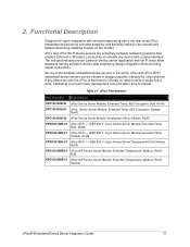
..., Bulk XPC10010MS-01 xPico IAP Device Server Module, Extended Temperature, Modbus, RoHS, Sample xPico® Embedded Device Server Integration Guide 10 xPico and xPico Wi-Fi device servers are extremely compact networking solution that there is virtually no need to device data simplifying design integration while providing robust connectivity. The included industry-proven Lantronix device server application and...
..., Bulk XPC10010MS-01 xPico IAP Device Server Module, Extended Temperature, Modbus, RoHS, Sample xPico® Embedded Device Server Integration Guide 10 xPico and xPico Wi-Fi device servers are extremely compact networking solution that there is virtually no need to device data simplifying design integration while providing robust connectivity. The included industry-proven Lantronix device server application and...

xPico - Integration Guide
Page 11
...module and RJ45 Jack is required for connection to a WLAN network. 2: Functional Description xPico Features The xPico device server contains Lantronix's own DSTni® EX controller, with 128KByte of SRAM and 1MByte of boot ROM, and integrated 10/100 PHY. xPico Wi-Fi Features The xPico Wi-Fi...required to interface to the 1MByte CPU embedded Flash) Power supply filters Reset circuit Note: xPico Wi-Fi units do not contain an integrated antenna. The xPico also contains the following : 3.3-volt serial interface 8 Configurable I/O pins All ...
...module and RJ45 Jack is required for connection to a WLAN network. 2: Functional Description xPico Features The xPico device server contains Lantronix's own DSTni® EX controller, with 128KByte of SRAM and 1MByte of boot ROM, and integrated 10/100 PHY. xPico Wi-Fi Features The xPico Wi-Fi...required to interface to the 1MByte CPU embedded Flash) Power supply filters Reset circuit Note: xPico Wi-Fi units do not contain an integrated antenna. The xPico also contains the following : 3.3-volt serial interface 8 Configurable I/O pins All ...

xPico - Integration Guide
Page 15
...An external Ethernet magnetic module and RJ45 is required to connect to an 802.11b/g/n wireless network. The serial interface pins include +3.3V, ground, and reset. All configurable I/O pins are 3.3V CMOS logic level and 5V tolerant. An external antenna attached to the xPico Wi-Fi U.FL connector is ...) are 3.3V CMOS logic level and 5V input tolerant. The serial signals usually connect to a standard 10/100Mbps Ethernet network. Table 2-2 xPico and xPico Wi-Fi Pin Connections Pin# xPico Wired 1 GND 3 CP8 5 RTS1 7 RXD1 9 GND 11 ETX13 ETX+ 15 GND 17 ERX19 ERX+ 21 GND 23 RXD2 25 ...
...An external Ethernet magnetic module and RJ45 is required to connect to an 802.11b/g/n wireless network. The serial interface pins include +3.3V, ground, and reset. All configurable I/O pins are 3.3V CMOS logic level and 5V tolerant. An external antenna attached to the xPico Wi-Fi U.FL connector is ...) are 3.3V CMOS logic level and 5V input tolerant. The serial signals usually connect to a standard 10/100Mbps Ethernet network. Table 2-2 xPico and xPico Wi-Fi Pin Connections Pin# xPico Wired 1 GND 3 CP8 5 RTS1 7 RXD1 9 GND 11 ETX13 ETX+ 15 GND 17 ERX19 ERX+ 21 GND 23 RXD2 25 ...

xPico - Integration Guide
Page 19
... board. It is USB2.0 Full Speed Host/Device/OTG capable. Mating connector data sheet: http://www.hirose.co.jp/cataloge_hp/e68440018.pdf Antenna Interface (xPico Wi-Fi Only) The xPico Wi-Fi module has been certified using the external antennas listed below , but from a different manufacturer part number the antenna gain must be equal to connect RTS...
... board. It is USB2.0 Full Speed Host/Device/OTG capable. Mating connector data sheet: http://www.hirose.co.jp/cataloge_hp/e68440018.pdf Antenna Interface (xPico Wi-Fi Only) The xPico Wi-Fi module has been certified using the external antennas listed below , but from a different manufacturer part number the antenna gain must be equal to connect RTS...

xPico - Integration Guide
Page 21
... RJ45 is located under the xPico Wi-Fi product line. RX- 2: Functional Description Figure 2-6 Reverse-SMA to U.FL(short) (P/N 500-182-R) Antenna Placement (xPico Wi-Fi only) When designing the xPico Wi-Fi module to a mating board, it is important to consider the final installation of adjacent circuit ... required in order to connect to the connecting access point for connection to antenna placement instructions located at http://www.lantronix.com/support/downloads/. Table 2-6 Ethernet Interface Signals Signal Name DIR Contact Primary Function Signal Requirement TX+ Out 13 ...
... RJ45 is located under the xPico Wi-Fi product line. RX- 2: Functional Description Figure 2-6 Reverse-SMA to U.FL(short) (P/N 500-182-R) Antenna Placement (xPico Wi-Fi only) When designing the xPico Wi-Fi module to a mating board, it is important to consider the final installation of adjacent circuit ... required in order to connect to the connecting access point for connection to antenna placement instructions located at http://www.lantronix.com/support/downloads/. Table 2-6 Ethernet Interface Signals Signal Name DIR Contact Primary Function Signal Requirement TX+ Out 13 ...

xPico - Integration Guide
Page 33
...section are applicable to both the xPico and the xPico Wi-Fi embedded device servers though the xPico pictures below are not required. Go to +85° Celsius, it is Lantronix part number XPC100A002-01-B. Figure 3-1 White Mounting Quick Clip Dimensions xPico® Embedded Device Server Integration ...pad be placed between the module and mating PCB. For temperature environments up to http://www.lantronix.com/products/cad-visio.html. 2. To Access CAD Files 1. For environments below . You may also directly access the CAD files through the Lantronix website. Click Download CAD ...
...section are applicable to both the xPico and the xPico Wi-Fi embedded device servers though the xPico pictures below are not required. Go to +85° Celsius, it is Lantronix part number XPC100A002-01-B. Figure 3-1 White Mounting Quick Clip Dimensions xPico® Embedded Device Server Integration ...pad be placed between the module and mating PCB. For temperature environments up to http://www.lantronix.com/products/cad-visio.html. 2. To Access CAD Files 1. For environments below . You may also directly access the CAD files through the Lantronix website. Click Download CAD ...

xPico - Integration Guide
Page 34
... Clip xPico/xPico Wi-Fi Module 2. 3: Mounting Instructions and PCB Footprint To Install the xPico or xPico Wi-Fi Module In the xPico Development Kit (Part Number XPC100100K-02) and xPico Wi-Fi Development Kit (XPW100100K-01), the xPico module comes installed to the Notification: Soldering Profile and Washing instruction located at http://www.lantronix.com/support/downloads/. The recommended heat pad is located under the xPico Wi-Fi product...
... Clip xPico/xPico Wi-Fi Module 2. 3: Mounting Instructions and PCB Footprint To Install the xPico or xPico Wi-Fi Module In the xPico Development Kit (Part Number XPC100100K-02) and xPico Wi-Fi Development Kit (XPW100100K-01), the xPico module comes installed to the Notification: Soldering Profile and Washing instruction located at http://www.lantronix.com/support/downloads/. The recommended heat pad is located under the xPico Wi-Fi product...

xPico - Integration Guide
Page 39
... periods may cause permanent damage to the xPico embedded device server. For xPico Wi-Fi operation above the rating listed in this table may affect the xPico's reliability. Specifications Electrical Specifications Caution: Stressing the device above +70° Celsuis, it is recommended that a heat pad be placed between the module and mating PCB. 4: Specifications 4. Parameter Supply...
... periods may cause permanent damage to the xPico embedded device server. For xPico Wi-Fi operation above the rating listed in this table may affect the xPico's reliability. Specifications Electrical Specifications Caution: Stressing the device above +70° Celsuis, it is recommended that a heat pad be placed between the module and mating PCB. 4: Specifications 4. Parameter Supply...