
Hardware Maintenance Manual
Page 5
... 25 Locating components 26 Accessing system board components and drives . . 27 Identifying parts on the system board . . . . . 28 Replacing memory 29 Replacing a PCI adapter 30 © Copyright IBM Corp. 2005 Replacing the battery 31 Replacing the power supply 32 Replacing the system board, ... . 22 Changing the startup device sequence . . . . 22 Advanced settings 22 Chapter 6. Parts listing 91 Machine Type 8127 91 Machine Type 8183 95 Machine Type 8184 109 Machine Type 8320 116 Machine Type 8416 125 Machine Type 8417 127 Machine Type 8418 133 Machine Type 8419 137...
... 25 Locating components 26 Accessing system board components and drives . . 27 Identifying parts on the system board . . . . . 28 Replacing memory 29 Replacing a PCI adapter 30 © Copyright IBM Corp. 2005 Replacing the battery 31 Replacing the power supply 32 Replacing the system board, ... . 22 Changing the startup device sequence . . . . 22 Advanced settings 22 Chapter 6. Parts listing 91 Machine Type 8127 91 Machine Type 8183 95 Machine Type 8184 109 Machine Type 8320 116 Machine Type 8416 125 Machine Type 8417 127 Machine Type 8418 133 Machine Type 8419 137...
Hardware Maintenance Manual
Page 9
... sources are announced and offered to identify which FRUs are hard disk drives, system boards, microprocessors, Liquid Crystal Displays (LCDs), and memory. hard disk drive, system board, microprocessor, LCD, and memory) v eSupport can be accessed at a MT - v The MTM portion of the machine label is the 4-digit MT and 3-digit CMV model...
... sources are announced and offered to identify which FRUs are hard disk drives, system boards, microprocessors, Liquid Crystal Displays (LCDs), and memory. hard disk drive, system board, microprocessor, LCD, and memory) v eSupport can be accessed at a MT - v The MTM portion of the machine label is the 4-digit MT and 3-digit CMV model...

Hardware Maintenance Manual
Page 11
...for a system maximum of 2 GB. Each DIMM socket can support up -to 1 GB of PC2700 double data rate (DDR) dynamic random access memory (SDRAM) for the following prompt on the computer you can find more information about the features on the logo screen: (To interrupt normal startup, press... Enter) Press Enter when you have Internet access, the most up to -date information for two 184-pin dual inline memory modules (DIMMs). Internal drives v 3.5-inch, half-inch (slim) diskette drive (some models) v Hard disk drive v Optical drives such as CD-ROM, DVD-...
...for a system maximum of 2 GB. Each DIMM socket can support up -to 1 GB of PC2700 double data rate (DDR) dynamic random access memory (SDRAM) for the following prompt on the computer you can find more information about the features on the logo screen: (To interrupt normal startup, press... Enter) Press Enter when you have Internet access, the most up to -date information for two 184-pin dual inline memory modules (DIMMs). Internal drives v 3.5-inch, half-inch (slim) diskette drive (some models) v Hard disk drive v Optical drives such as CD-ROM, DVD-...

Hardware Maintenance Manual
Page 12
... serial connectors v Eight USB 2.0 connectors (two on front panel and six on front panel Expansion v Two 32-bit PCI full height adapter slots v Two DIMM memory connectors Power v 200 Watt power supply with manual voltage selection switch v Automatic 50/60 Hz input frequency switching v Advanced Power Management support v Advanced Configuration and...
... serial connectors v Eight USB 2.0 connectors (two on front panel and six on front panel Expansion v Two 32-bit PCI full height adapter slots v Two DIMM memory connectors Power v 200 Watt power supply with manual voltage selection switch v Automatic 50/60 Hz input frequency switching v Advanced Power Management support v Advanced Configuration and...
Hardware Maintenance Manual
Page 17
... go to Chapter 7, "Symptom-to the information supplied with that software package. Check for Type 8127, 8183, 8184, 8320, 8416, 8417, 8418, 8419, and 8429 computers. Chapter 3. v To enable beep and memory count and checkpoint code display when a successful POST occurs, do the following response: © Copyright IBM ...Corp. 2005 11 Set Power-On Self-Test to boot up quiet (no beep and no memory count and checkpoint code display) when no error is installed on page 147. Make sure the system board is found by POST. Diagnostic error...
... go to Chapter 7, "Symptom-to the information supplied with that software package. Check for Type 8127, 8183, 8184, 8320, 8416, 8417, 8418, 8419, and 8429 computers. Chapter 3. v To enable beep and memory count and checkpoint code display when a successful POST occurs, do the following response: © Copyright IBM ...Corp. 2005 11 Set Power-On Self-Test to boot up quiet (no beep and no memory count and checkpoint code display) when no error is installed on page 147. Make sure the system board is found by POST. Diagnostic error...
Hardware Maintenance Manual
Page 25
.... When working with the IBM Setup Utility program menu, you see the prompt. 3. If you might have to set a password of either one, read -only memory (EEPROM) of each screen. Otherwise, your password. There are displayed at the bottom of the computer. However, the operating-system settings might start the IBM...
.... When working with the IBM Setup Utility program menu, you see the prompt. 3. If you might have to set a password of either one, read -only memory (EEPROM) of each screen. Otherwise, your password. There are displayed at the bottom of the computer. However, the operating-system settings might start the IBM...
Hardware Maintenance Manual
Page 32
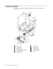
Locating components The following illustration will help you locate the various components in the computer. 1 2 3 13 12 8 9 10 4 5 6 7 11 1 Cover 2 Power supply 3 Optical drive 4 Hard disk drive 5 Rotating drive bay assembly 6 Front plastic bezel 7 Diskette drive 8 Heat sink 9 Microprocessor 10 System board 11 Memory module 12 PCI riser assembly 13 Chassis 26 Hardware Maintenance Manual
Locating components The following illustration will help you locate the various components in the computer. 1 2 3 13 12 8 9 10 4 5 6 7 11 1 Cover 2 Power supply 3 Optical drive 4 Hard disk drive 5 Rotating drive bay assembly 6 Front plastic bezel 7 Diskette drive 8 Heat sink 9 Microprocessor 10 System board 11 Memory module 12 PCI riser assembly 13 Chassis 26 Hardware Maintenance Manual
Hardware Maintenance Manual
Page 33
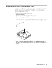
... of any cable connectors and the routing of the cables before you might need to different or higher capacity drives. Rotate the drives upward as memory, the battery, and the Clear CMOS/BIOS recovery jumper, you disconnect from the riser card. See "Replacing a PCI adapter" on page 25. 3. If any adapters...
... of any cable connectors and the routing of the cables before you might need to different or higher capacity drives. Rotate the drives upward as memory, the battery, and the Clear CMOS/BIOS recovery jumper, you disconnect from the riser card. See "Replacing a PCI adapter" on page 25. 3. If any adapters...
Hardware Maintenance Manual
Page 34
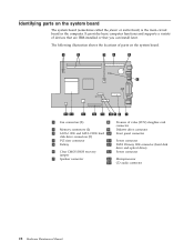
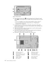
... or motherboard) is the main circuit board in the computer. Identifying parts on the system board. 1 Fan connectors (2) 8 Promise of value (POV) daughter card connector 2 Memory connectors (2) 9 Diskette drive connector 3 SATA 1 IDE and SATA 2 IDE hard 10 Front panel connector disk drive connectors (2) 4 PCI riser connector 11 Power connector 5 Battery 12...
... or motherboard) is the main circuit board in the computer. Identifying parts on the system board. 1 Fan connectors (2) 8 Promise of value (POV) daughter card connector 2 Memory connectors (2) 9 Diskette drive connector 3 SATA 1 IDE and SATA 2 IDE hard 10 Front panel connector disk drive connectors (2) 4 PCI riser connector 11 Power connector 5 Battery 12...
Hardware Maintenance Manual
Page 35
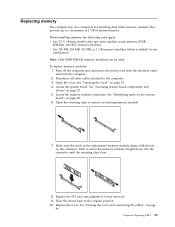
... connecting the cables" on page 28. 6. See "Opening the cover" on page 27. 5. Locate the memory module connectors. Replace the cover. Note: Only DDR SDRAM memory moduless can be used. Make sure the notch in any combination. Open the cover. Open the retaining clips ... attached to a maximum of 2 GB of system memory. v Use 128 MB, 256 MB, 512 MB, or 1 GB memory modules (when available) in the replacement memory module aligns with the tab on the connector. Replacing memory The computer has two connectors for installing dual inline memory modules that provide up to the computer. 3.
... connecting the cables" on page 28. 6. See "Opening the cover" on page 27. 5. Locate the memory module connectors. Replace the cover. Note: Only DDR SDRAM memory moduless can be used. Make sure the notch in any combination. Open the cover. Open the retaining clips ... attached to a maximum of 2 GB of system memory. v Use 128 MB, 256 MB, 512 MB, or 1 GB memory modules (when available) in the replacement memory module aligns with the tab on the connector. Replacing memory The computer has two connectors for installing dual inline memory modules that provide up to the computer. 3.
Hardware Maintenance Manual
Page 37
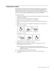
... the IBM Setup Utility program to the computer. 3. Turn on page 28 and locate the battery. 5. Replacing the battery The computer has a special type of memory that impede access to "Identifying parts on the system board" on the computer and all other cables attached to set the date and time and...
... the IBM Setup Utility program to the computer. 3. Turn on page 28 and locate the battery. 5. Replacing the battery The computer has a special type of memory that impede access to "Identifying parts on the system board" on the computer and all other cables attached to set the date and time and...
Hardware Maintenance Manual
Page 42
.... Disconnect the diskette drive cable from the system board by sliding the plastic cable retainer upward to the system board. 1 Microprocessor heat sink 2 Fan connectors (2) 3 memory module connectors (2) 4 SATA 1 IDE and SATA 2 IDE connectors (2) 5 PCI riser connector 6 Speaker connector 7 POV connector 36 Hardware Maintenance Manual 8 Diskette drive connector 9 Front panel connector...
.... Disconnect the diskette drive cable from the system board by sliding the plastic cable retainer upward to the system board. 1 Microprocessor heat sink 2 Fan connectors (2) 3 memory module connectors (2) 4 SATA 1 IDE and SATA 2 IDE connectors (2) 5 PCI riser connector 6 Speaker connector 7 POV connector 36 Hardware Maintenance Manual 8 Diskette drive connector 9 Front panel connector...
Hardware Maintenance Manual
Page 43
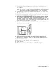
Install the memory modules on the system board being replaced. 18. Slide the system board assembly to the rear until the front edge of the system board assembly ... of the system board assembly with the slots in the same location as they were on the new system board in the rear of the memory memory modules and remove them from the system board. 17. Replacing FRUs 37 Using the two blue handles provided, lift the system board assembly out of...
Install the memory modules on the system board being replaced. 18. Slide the system board assembly to the rear until the front edge of the system board assembly ... of the system board assembly with the slots in the same location as they were on the new system board in the rear of the memory memory modules and remove them from the system board. 17. Replacing FRUs 37 Using the two blue handles provided, lift the system board assembly out of...
Hardware Maintenance Manual
Page 55
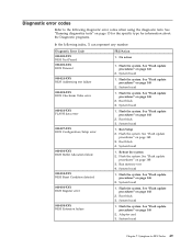
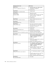
... system. Flash the system. Boot block 3. Reboot the system 2. See "Flash update procedures" on page 148 2. System board Chapter 7. Flash the system. System board 1. Run memory test 4. Run Setup 2. Boot block 4. Flash the system. System board 1. Flash the system. System board 1. No action 1. System board 1. System board 1. See "Flash update procedures...
... system. Flash the system. Boot block 3. Reboot the system 2. See "Flash update procedures" on page 148 2. System board Chapter 7. Flash the system. System board 1. Run memory test 4. Run Setup 2. Boot block 4. Flash the system. System board 1. Flash the system. System board 1. No action 1. System board 1. System board 1. See "Flash update procedures...
Hardware Maintenance Manual
Page 57
See "Flash update procedures" on page 148 3. Flash the system. System board 1. Run memory test 4. System board 1. Press F3 to -FRU Index 51 Replace the component under test Chapter 7. Run Setup 2. System board 1. System board 1. Re-start the test, ...
See "Flash update procedures" on page 148 3. Flash the system. System board 1. Run memory test 4. System board 1. Press F3 to -FRU Index 51 Replace the component under test Chapter 7. Run Setup 2. System board 1. System board 1. Re-start the test, ...
Hardware Maintenance Manual
Page 64
Flash the system and re-test. Run memory test 4. Information 2. Re-start the test, if necessary 1. See Chapter 5, "Using the IBM Setup Utility," on page 148 3. Replace the component under function test 1. Flash ...
Flash the system and re-test. Run memory test 4. Information 2. Re-start the test, if necessary 1. See Chapter 5, "Using the IBM Setup Utility," on page 148 3. Replace the component under function test 1. Flash ...
Hardware Maintenance Manual
Page 73
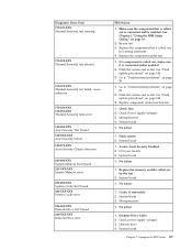
...run test 3. Flash the system and re-test. Go to "Undetermined problems" on page 148 3. Microprocessor 4. System board 1. System board 1. Replace the memory module called out, make sure it is called out in warning statement 4. Cache, if removable 2. Diskette drive 4. Replace the component under function test 1.... Security Test Passed 185-XXX-XXX Asset Security failure 185-278-XXX Asset Security Chassis Intrusion 201-000-XXX System Memory Test Passed 201-XXX-XXX System Memory error 202-000-XXX System Cache Test Passed 202-XXX-XXX System Cache error 206-000-XXX Diskette Drive Test ...
...run test 3. Flash the system and re-test. Go to "Undetermined problems" on page 148 3. Microprocessor 4. System board 1. System board 1. Replace the memory module called out, make sure it is called out in warning statement 4. Cache, if removable 2. Diskette drive 4. Replace the component under function test 1.... Security Test Passed 185-XXX-XXX Asset Security failure 185-278-XXX Asset Security Chassis Intrusion 201-000-XXX System Memory Test Passed 201-XXX-XXX System Memory error 202-000-XXX System Cache Test Passed 202-XXX-XXX System Cache error 206-000-XXX Diskette Drive Test ...
Hardware Maintenance Manual
Page 77
Jumper on J28 2. System Board 1. System Board 1. Beep Symptom 2-2-4 CMOS configuration info validation failed 2-3-1 Screen initialization failed 2-3-2 Screen memory failed 2-3-3 Screen retrace failed 1-2 Search for video ROM failed All other beep code sequences Continuous beep Repeating short beeps FRU/Action 1. System Board 1. Keyboard stuck key 2. System Board 1. System Board Chapter 7. Symptom-to-FRU Index 71 System Board 1. Battery 2. System Board 1. Keyboard Cable 3. System Board 1.
Jumper on J28 2. System Board 1. System Board 1. Beep Symptom 2-2-4 CMOS configuration info validation failed 2-3-1 Screen initialization failed 2-3-2 Screen memory failed 2-3-3 Screen retrace failed 1-2 Search for video ROM failed All other beep code sequences Continuous beep Repeating short beeps FRU/Action 1. System Board 1. Keyboard stuck key 2. System Board 1. System Board Chapter 7. Symptom-to-FRU Index 71 System Board 1. Battery 2. System Board 1. Keyboard Cable 3. System Board 1.
Hardware Maintenance Manual
Page 78
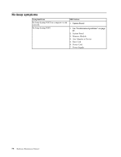
No beep during POST but computer works correctly. Any Adapter or Device 5. See "Undetermined problems" on page 89. 2. System Board 3. FRU/Action 1. Power Supply 72 Hardware Maintenance Manual Memory Module 4. Riser Card 6. System Board 1. Power Cord 7. No-beep symptoms Symptom/Error No beep during POST.
No beep during POST but computer works correctly. Any Adapter or Device 5. See "Undetermined problems" on page 89. 2. System Board 3. FRU/Action 1. Power Supply 72 Hardware Maintenance Manual Memory Module 4. Riser Card 6. System Board 1. Power Cord 7. No-beep symptoms Symptom/Error No beep during POST.
Hardware Maintenance Manual
Page 79
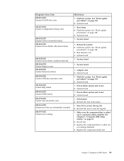
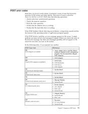
...called the Power-On Self-Test, or POST. See documentation shipped with computer. 1. SCSI Terminator 3. System Board 1. System Board 1. Adapter Memory 2. Symptom-to appear. Verify adapter device and Bus Master fields are enabled in PCI configuration program. System Board 1. System Board 3. Riser card... not enabled 02X 08X Check SCSI terminator installation. 101 System board interrupt failure 102 System board timer error 106 110 System board memory parity error 111 I/O channel parity error 114 Adapter ROM error 129 Internal cache test error FRU/Action 1. SCSI Adapter 1. SCSI...
...called the Power-On Self-Test, or POST. See documentation shipped with computer. 1. SCSI Terminator 3. System Board 1. System Board 1. Adapter Memory 2. Symptom-to appear. Verify adapter device and Bus Master fields are enabled in PCI configuration program. System Board 1. System Board 3. Riser card... not enabled 02X 08X Check SCSI terminator installation. 101 System board interrupt failure 102 System board timer error 106 110 System board memory parity error 111 I/O channel parity error 114 Adapter ROM error 129 Internal cache test error FRU/Action 1. SCSI Adapter 1. SCSI...


