

Service Manual
Page 4
... Blank Page 2-14 Blurred or Fuzzy Print 2-15 Dead Machine 2-15 Duplex 2-16 Fan (927 Error 2-18 Fuser Theory 2-19 Fuser: 920, 921, or 922 Error 2-19 Fuser: 923 or 924 Error 2-20 Honeycomb 2-20 Horizontal Void or Streak 2-20 LAN Problems 2-21 Light Print 2-21 Network Card 977 Errors 2-21 Network Wrap Tests 2-22 Output Bin Sensor 2-22 Operator Panel Problem 2-22 Paper Feed Problem, 500-Sheet Option or 200-Sheet Second Drawer, Non-Rt 2-23 Paper Feed, Base Printer 2-23 Paper Feed, Duplex Unit 2-25 Paper Feed Problem, Envelope+ Feeder...
... Blank Page 2-14 Blurred or Fuzzy Print 2-15 Dead Machine 2-15 Duplex 2-16 Fan (927 Error 2-18 Fuser Theory 2-19 Fuser: 920, 921, or 922 Error 2-19 Fuser: 923 or 924 Error 2-20 Honeycomb 2-20 Horizontal Void or Streak 2-20 LAN Problems 2-21 Light Print 2-21 Network Card 977 Errors 2-21 Network Wrap Tests 2-22 Output Bin Sensor 2-22 Operator Panel Problem 2-22 Paper Feed Problem, 500-Sheet Option or 200-Sheet Second Drawer, Non-Rt 2-23 Paper Feed, Base Printer 2-23 Paper Feed, Duplex Unit 2-25 Paper Feed Problem, Envelope+ Feeder...

Service Manual
Page 23
...; "Repair Information" provides instructions for individual FRUs. Preface xxiii Special tools and test equipment are listed in this chapter. • "Diagnostic Information" contains error code table, symptom table, and service checks used to isolate failing field replaceable units (FRUs). • "Diagnostic Aids" contains tests and checks used to locate or repeat symptoms of the printer, available options, and the maintenance approach used to prevent problems and maintain optimum performance. • "Parts...
...; "Repair Information" provides instructions for individual FRUs. Preface xxiii Special tools and test equipment are listed in this chapter. • "Diagnostic Information" contains error code table, symptom table, and service checks used to isolate failing field replaceable units (FRUs). • "Diagnostic Aids" contains tests and checks used to locate or repeat symptoms of the printer, available options, and the maintenance approach used to prevent problems and maintain optimum performance. • "Parts...

Service Manual
Page 27
... VAC VDC Application-Specific Integrated Circuit Customer Setup Dynamic Random Access Memory Electrically Erasable Programmable ReadOnly Memory Electrophotographic Process Electrostatic Discharge Field Replaceable Unit High Voltage Power Supply Local Area Network Light Amplification by Stimulated Emission of Radiation Liquid Crystal Display Light-Emitting Diode Low Voltage Power Supply Nonvolatile Random Access Memory Original Equipment Manufacturer Problem Isolation Charts Picture Element Power-On Reset Power-On Self Test Print Quality Enhancement Technology Raster Image Processor Read-Only...
... VAC VDC Application-Specific Integrated Circuit Customer Setup Dynamic Random Access Memory Electrically Erasable Programmable ReadOnly Memory Electrophotographic Process Electrostatic Discharge Field Replaceable Unit High Voltage Power Supply Local Area Network Light Amplification by Stimulated Emission of Radiation Liquid Crystal Display Light-Emitting Diode Low Voltage Power Supply Nonvolatile Random Access Memory Original Equipment Manufacturer Problem Isolation Charts Picture Element Power-On Reset Power-On Self Test Print Quality Enhancement Technology Raster Image Processor Read-Only...

Service Manual
Page 29
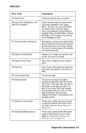
... . Duplex unit is installed but paper tray is too short to print data as formatted. The output bin sensor has not been unmade.See "Output Bin Sensor" on page 2-16 The defined paper size is not sensed. Diagnostic Information 2-2 Jam at wrong time. Paper is either not leaving the duplex entry sensor in time or not making or unmaking the duplex exit sensor in time. Error Code 20 Paper Jam 21 Paper Jam 22 Paper Jam 23 Paper Jam 24 Short Paper 25 Incorrect Manual Feed 26 Duplex Tray Missing 27 Change Envelope/Paper 28 Load Envelope/Paper...
... . Duplex unit is installed but paper tray is too short to print data as formatted. The output bin sensor has not been unmade.See "Output Bin Sensor" on page 2-16 The defined paper size is not sensed. Diagnostic Information 2-2 Jam at wrong time. Paper is either not leaving the duplex entry sensor in time or not making or unmaking the duplex exit sensor in time. Error Code 20 Paper Jam 21 Paper Jam 22 Paper Jam 23 Paper Jam 24 Short Paper 25 Incorrect Manual Feed 26 Duplex Tray Missing 27 Change Envelope/Paper 28 Load Envelope/Paper...

Service Manual
Page 30
... installed memory, go to the user menus and print the "Print Menus" test page. Memory is full. Make sure the memory shown on the printout matches the installed memory. Not enough flash memory for data requested to write. 2-3 Make sure the memory shown on the printout matches the installed memory. Font card format not supported by the Optra printer. Memory used to store pages is too full to collate the print job. Defective font card installed in font slot. If the error recurs replace the Flash...
... installed memory, go to the user menus and print the "Print Menus" test page. Memory is full. Make sure the memory shown on the printout matches the installed memory. Not enough flash memory for data requested to write. 2-3 Make sure the memory shown on the printout matches the installed memory. Font card format not supported by the Optra printer. Memory used to store pages is too full to collate the print job. Defective font card installed in font slot. If the error recurs replace the Flash...
Service Manual
Page 31
... "Scheduled Mechanical Maintenance" on page 6-3. Check the auto-connect plugs on page 2-22 Printer has reached 200,000 prints without maintenance count reset. Replace the disk if instructed by entering the customer setup menu and selecting Serial Setup or Parallel Setup, Serial Buffer or Parallel Buffer, and changing the setting from the printer but the disk does not work, run the Disk Test/Clean (2 hour test). See "Network Wrap Tests" on the duplex unit and the printer. Refer to a port which has been disabled in various network card user manuals. Diagnostic...
... "Scheduled Mechanical Maintenance" on page 6-3. Check the auto-connect plugs on page 2-22 Printer has reached 200,000 prints without maintenance count reset. Replace the disk if instructed by entering the customer setup menu and selecting Serial Setup or Parallel Setup, Serial Buffer or Parallel Buffer, and changing the setting from the printer but the disk does not work, run the Disk Test/Clean (2 hour test). See "Network Wrap Tests" on the duplex unit and the printer. Refer to a port which has been disabled in various network card user manuals. Diagnostic...

Service Manual
Page 40
... the contacts on coated paper or using refilled print cartridges can cause background on some print quality improvement from increasing the Transfer setting; users with the RIP Board removed and check the following voltages; if Rough Paper mode is on the entire photo- 2-13 Users who run the print test again. Make sure the HVPS contacts to ground should turn it off and run large jobs with very dense...
... the contacts on coated paper or using refilled print cartridges can cause background on some print quality improvement from increasing the Transfer setting; users with the RIP Board removed and check the following voltages; if Rough Paper mode is on the entire photo- 2-13 Users who run the print test again. Make sure the HVPS contacts to ground should turn it off and run large jobs with very dense...

Service Manual
Page 47
... 924 Error Check the connection and continuity of the print cartridge and printhead shutter. it does not, replace the LVPS, the fuser, and the fuser wiper. Make sure the HVPS ground lead to J8-4. Check the thermistor resistance at engine board J8-3 to the side frame is touching the contact on page 2-14 and follow those instructions. Diagnostic Information 2-20 If the lamp, fuser power cable...
... 924 Error Check the connection and continuity of the print cartridge and printhead shutter. it does not, replace the LVPS, the fuser, and the fuser wiper. Make sure the HVPS ground lead to J8-4. Check the thermistor resistance at engine board J8-3 to the side frame is touching the contact on page 2-14 and follow those instructions. Diagnostic Information 2-20 If the lamp, fuser power cable...

Service Manual
Page 48
If the network card checks out successfully, the problem may appear lighter than PCL emulation output or a test print; Light Print Light print is set to the customer for checking hardware and software for the displayed error code. 2-21 See "Blank Page" on the Print Test that the print is too light before performing service. Make sure Print Darkness on the customer menu is frequently caused by powering on and off two or three times, leaving the printer on for "Blank Page". Network Card 977 Errors All network card errors are some...
If the network card checks out successfully, the problem may appear lighter than PCL emulation output or a test print; Light Print Light print is set to the customer for checking hardware and software for the displayed error code. 2-21 See "Blank Page" on the Print Test that the print is too light before performing service. Make sure Print Darkness on the customer menu is frequently caused by powering on and off two or three times, leaving the printer on for "Blank Page". Network Card 977 Errors All network card errors are some...

Service Manual
Page 50
... operator panel card, cable or connector problem, or engine board problem. With 500-sheet trays, make sure the paper is in the tray correctly and is set high enough to ground (J15-3). Run the diagnostic tests for the LCD and for other mechanical problems or damage. If paper is not feeding, make sure the gear train is installed. Replace the operator panel or the cable if they are wrong. Paper Feed, Base Printer...
... operator panel card, cable or connector problem, or engine board problem. With 500-sheet trays, make sure the paper is in the tray correctly and is set high enough to ground (J15-3). Run the diagnostic tests for the LCD and for other mechanical problems or damage. If paper is not feeding, make sure the gear train is installed. Replace the operator panel or the cable if they are wrong. Paper Feed, Base Printer...

Service Manual
Page 53
... table cover and reinstalling the duplex unit in the wrong connector; 4049-XXX If paper is jamming at the front exit of the printer, inspect the duplex exit selector switch and the linkage to J17-4; The voltage will change from 105 Ohms to J10-2 on the engine board. feeder cable loose, disconnected, or plugged in the printer. If Tray 2 is not on the Paper Feed Test menu, make...
... table cover and reinstalling the duplex unit in the wrong connector; 4049-XXX If paper is jamming at the front exit of the printer, inspect the duplex exit selector switch and the linkage to J17-4; The voltage will change from 105 Ohms to J10-2 on the engine board. feeder cable loose, disconnected, or plugged in the printer. If Tray 2 is not on the Paper Feed Test menu, make...

Service Manual
Page 56
... that all paper feed problems: Verify that the printer designator switch on the feeder. Look between the two models. Failure to feed: Check the printer Paper Source menu for a "Tray 2" indication to be manually picked by rotating the paper feed rollers by hand, or by opening and closing the door, with alcohol or water; Make sure the paper is set to the correct printer model being used. Make sure that the corner bucklers are available. Envelopes and...
... that all paper feed problems: Verify that the printer designator switch on the feeder. Look between the two models. Failure to feed: Check the printer Paper Source menu for a "Tray 2" indication to be manually picked by rotating the paper feed rollers by hand, or by opening and closing the door, with alcohol or water; Make sure the paper is set to the correct printer model being used. Make sure that the corner bucklers are available. Envelopes and...

Service Manual
Page 57
... engine board J12-8. If the elevator raises normally but the printer does not become Ready, the signal from the feeder ready switch is incorrect, replace the engine board. It contains no pin should be inspected by removing the cover, positioning it near the feeder, reconnecting the power supply and door switch cables, and reconnecting the line cord. When replacing the circuit board, check the A4/U.S.
... engine board J12-8. If the elevator raises normally but the printer does not become Ready, the signal from the feeder ready switch is incorrect, replace the engine board. It contains no pin should be inspected by removing the cover, positioning it near the feeder, reconnecting the power supply and door switch cables, and reconnecting the line cord. When replacing the circuit board, check the A4/U.S.

Service Manual
Page 69
... Network Card errors are received, the oldest error is discarded. Flash Test This test writes to and reads from Normal to No Boost; The operator panel will display [Passed] or [Failed]. 4. Reduce the setting from the flash memory. If the same error occurs consecutively it is the oldest error. Select [CLEAR] and then [CONTINUE] to the Diagnostics mode main menu. Select [DEVICE TESTS]. 3. Press Return to return to clear the error...
... Network Card errors are received, the oldest error is discarded. Flash Test This test writes to and reads from Normal to No Boost; The operator panel will display [Passed] or [Failed]. 4. Reduce the setting from the flash memory. If the same error occurs consecutively it is the oldest error. Select [CLEAR] and then [CONTINUE] to the Diagnostics mode main menu. Select [DEVICE TESTS]. 3. Press Return to return to clear the error...

Service Manual
Page 71
... feed paper through the printer to check for broken gear teeth, watch the paper path, or check the erase lamps.You may want in each digit. Diagnostic Aids 3-10 Select [Reset] to set the page count: 1. Memory Tests 1. Select [CANCEL] to "0". 5. Enter Diagnostics mode. 2. Select [+] or [-] to select the number you want to prevent the [80 Scheduled Maintenance] message from displaying when the machine is replaced to remove the gear cover...
... feed paper through the printer to check for broken gear teeth, watch the paper path, or check the erase lamps.You may want in each digit. Diagnostic Aids 3-10 Select [Reset] to set the page count: 1. Memory Tests 1. Select [CANCEL] to "0". 5. Enter Diagnostics mode. 2. Select [+] or [-] to select the number you want to prevent the [80 Scheduled Maintenance] message from displaying when the machine is replaced to remove the gear cover...
Service Manual
Page 77
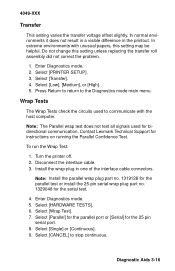
... pin serial port. 8. Disconnect the interface cable. 3. Select [HARDWARE TESTS]. 6. Select [Parallel] for the parallel port or [Serial] for the serial test. 4. Do not change this setting may be helpful. To run the Wrap Test: 1. Select [Low], [Medium], or [High]. 5. Select [CANCEL] to the Diagnostics mode main menu. Diagnostic Aids 3-16 Note: The Parallel wrap test does not test all signals used to communicate with unusual papers, this setting unless replacing the transfer...
... pin serial port. 8. Disconnect the interface cable. 3. Select [HARDWARE TESTS]. 6. Select [Parallel] for the parallel port or [Serial] for the serial test. 4. Do not change this setting may be helpful. To run the Wrap Test: 1. Select [Low], [Medium], or [High]. 5. Select [CANCEL] to the Diagnostics mode main menu. Diagnostic Aids 3-16 Note: The Parallel wrap test does not test all signals used to communicate with unusual papers, this setting unless replacing the transfer...

Service Manual
Page 78
... The printer test page indicates to which type of the paper is connected.The Network external connectors are shown below. 3-17 Press Return to return to get the timing correct. Other Tests Developed Image Test Use the Developed Image Test to isolate print quality problems. You might have to practice this procedure several times to the Diagnostics mode main menu. 11. conductor. Print the test page. 3. To run the Developed Image Test: 1. Note: Ignore the number displayed...
... The printer test page indicates to which type of the paper is connected.The Network external connectors are shown below. 3-17 Press Return to return to get the timing correct. Other Tests Developed Image Test Use the Developed Image Test to isolate print quality problems. You might have to practice this procedure several times to the Diagnostics mode main menu. 11. conductor. Print the test page. 3. To run the Developed Image Test: 1. Note: Ignore the number displayed...

Service Manual
Page 79
... lines spaced about an inch apart down the page. In this test to test the printer without the RIP board installed. This test prints from the userselected default paper tray. Select [TESTS MENU]. 4. ous test pages. 6. service codes are not displayed and most error-handling is a continuous print test; Select [Print Test Page]. 5. Remove the RIP board and the inner EMC shield together and power on . 2. The test consists of printer microcode. Diagnostic Aids 3-18 Use this mode, the operator panel...
... lines spaced about an inch apart down the page. In this test to test the printer without the RIP board installed. This test prints from the userselected default paper tray. Select [TESTS MENU]. 4. ous test pages. 6. service codes are not displayed and most error-handling is a continuous print test; Select [Print Test Page]. 5. Remove the RIP board and the inner EMC shield together and power on . 2. The test consists of printer microcode. Diagnostic Aids 3-18 Use this mode, the operator panel...

Service Manual
Page 191
... image test 3-17 diagnostics mode 3-1 diagnostics mode menus device tests 3-2 duplex tests 3-2 hardware tests 3-1 page count tests 3-2 paper feed tests 3-2 print registration tests 3-1 print tests 3-1 printer setup tests 3-2 diamonds on display 2-34 disk test/clean 3-5 drive motor removal 4-14 D-roll assembly removal 4-14 duplex 23 paper jam 2-17 933 error 2-17 diagnosis 2-16 paper feed problem 2-25 duplex feed 1 test 3-6 duplex feed 2 test 3-6 duplex option autoconnect cable connectors 5-10 bottom cover removal 4-41 entry sensor card removal 4-41 exit card and cover removal 4-40 parts...
... image test 3-17 diagnostics mode 3-1 diagnostics mode menus device tests 3-2 duplex tests 3-2 hardware tests 3-1 page count tests 3-2 paper feed tests 3-2 print registration tests 3-1 print tests 3-1 printer setup tests 3-2 diamonds on display 2-34 disk test/clean 3-5 drive motor removal 4-14 D-roll assembly removal 4-14 duplex 23 paper jam 2-17 933 error 2-17 diagnosis 2-16 paper feed problem 2-25 duplex feed 1 test 3-6 duplex feed 2 test 3-6 duplex option autoconnect cable connectors 5-10 bottom cover removal 4-41 entry sensor card removal 4-41 exit card and cover removal 4-40 parts...
Service Manual
Page 192
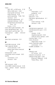
... removal 4-26 inner EMC shield removal 4-35 input sensor board removal 4-26 L LAN information 3-17 problems 2-21 LCD test 3-9 light print 2-21 lubrication specifications 6-1 LVPS cover removal 4-30 removal 4-29 M maintenance approach 1-3 maintenance kit count 3-10 marks random 2-32 regularly spaced 2-32 vertical void or streak 2-34 memory tests 3-10 menu structure diagnostics mode 3-1 mirror motor/fan cable connectors 5-7 models available 1-1 N network card 977 errors 2-21 network connectors 3-17 network wrap tests 2-22 Ethernet 10Base-2 2-22 Token-Ring 2-22 X-3 Service Manual
... removal 4-26 inner EMC shield removal 4-35 input sensor board removal 4-26 L LAN information 3-17 problems 2-21 LCD test 3-9 light print 2-21 lubrication specifications 6-1 LVPS cover removal 4-30 removal 4-29 M maintenance approach 1-3 maintenance kit count 3-10 marks random 2-32 regularly spaced 2-32 vertical void or streak 2-34 memory tests 3-10 menu structure diagnostics mode 3-1 mirror motor/fan cable connectors 5-7 models available 1-1 N network card 977 errors 2-21 network connectors 3-17 network wrap tests 2-22 Ethernet 10Base-2 2-22 Token-Ring 2-22 X-3 Service Manual

