

Service Manual
Page 30
... the user menus and print the "Print Menus" test page. Printer needs data on the print cartridge as the cover closes. Font card format not supported by the Optra printer. 4049-XXX Error Code 30 Top Cover Open or Print Cartridge Missing 32 Wrong Print Cartridge installed 37 Insufficient Collation Memory 38 Memory Full 39 Complex...
... the user menus and print the "Print Menus" test page. Printer needs data on the print cartridge as the cover closes. Font card format not supported by the Optra printer. 4049-XXX Error Code 30 Top Cover Open or Print Cartridge Missing 32 Wrong Print Cartridge installed 37 Insufficient Collation Memory 38 Memory Full 39 Complex...

Service Manual
Page 41
... spring back when pressed. Check the condition of each HVPS contact and make sure the actuator on top of the cartridge is present and extends into the printhead shroud when the printer top cover is making contact with the RIP Board removed. Make the following voltages are not correct, replace the engine...
... spring back when pressed. Check the condition of each HVPS contact and make sure the actuator on top of the cartridge is present and extends into the printhead shroud when the printer top cover is making contact with the RIP Board removed. Make the following voltages are not correct, replace the engine...
Service Manual
Page 48
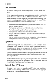
...print; Verify on for possible problems. Refer the customer to the LaserPrinter Network Printer Utility Guide to Normal or Dark. If there are some suggestions to operations. Clean the transfer roll by a worn out print cartridge. Light Print Light print is frequently caused by powering on and off two or... three times, leaving the printer on the Print Test that the print is not a defect. this is too light before...
...print; Verify on for possible problems. Refer the customer to the LaserPrinter Network Printer Utility Guide to Normal or Dark. If there are some suggestions to operations. Clean the transfer roll by a worn out print cartridge. Light Print Light print is frequently caused by powering on and off two or... three times, leaving the printer on the Print Test that the print is not a defect. this is too light before...

Service Manual
Page 59
To test the erase lamps, jumper engine board J9-2 to foreign matter loose in the printer or in the print cartridge. Residual Image Residual image--the "walking" of a leftover image down the page--is +24 VDC and that the cable has continuity. Random Marks Random marks ... lamp voltage at engine board J91 is probably the result of failed erase lamps not discharging the photoconductor, or of a failed cleaner inside the print cartridge. Find and replace the damaged part. 4049-XXX Regularly Spaced Marks This is caused by the spacing of the marks according to the following table.
To test the erase lamps, jumper engine board J9-2 to foreign matter loose in the printer or in the print cartridge. Residual Image Residual image--the "walking" of a leftover image down the page--is +24 VDC and that the cable has continuity. Random Marks Random marks ... lamp voltage at engine board J91 is probably the result of failed erase lamps not discharging the photoconductor, or of a failed cleaner inside the print cartridge. Find and replace the damaged part. 4049-XXX Regularly Spaced Marks This is caused by the spacing of the marks according to the following table.

Service Manual
Page 78
...paper is visible coming out the front exit slot, turn off , and remove the wrap plug from the interface connector. Remove the print cartridge and look at the image on the photo- Press Return to return to get the timing correct. Note: Ignore the number displayed after a... Diagnostics mode main menu. 11. A [Failed] message indicates a defective RIP board. Turn the printer off the printer. 4. To run the Developed Image Test: 1. Print the test page. 3. LAN Information The printer may be connected to one of the following LAN types: Token-Ring Ethernet 10BASE-T Ethernet 10BASE2 LocalTalk...
...paper is visible coming out the front exit slot, turn off , and remove the wrap plug from the interface connector. Remove the print cartridge and look at the image on the photo- Press Return to return to get the timing correct. Note: Ignore the number displayed after a... Diagnostics mode main menu. 11. A [Failed] message indicates a defective RIP board. Turn the printer off the printer. 4. To run the Developed Image Test: 1. Print the test page. 3. LAN Information The printer may be connected to one of the following LAN types: Token-Ring Ethernet 10BASE-T Ethernet 10BASE2 LocalTalk...

Service Manual
Page 97
... FOR 5 MINUTES. 1. Disconnect the power wires [A] from the fuser. 4. Remove the fuser cover. 5. Completely loosen the four fuser mounting screws. 8. Repair Information 4-18 Remove the printer cartridge. 3. Remove the fuser input guide. 7. Unplug the power cord. 2. Lift the fuser out of the fuser. 6. CAUTION: THE TEMPERATURE OF THE HOT ROLLER IS 150...
... FOR 5 MINUTES. 1. Disconnect the power wires [A] from the fuser. 4. Remove the fuser cover. 5. Completely loosen the four fuser mounting screws. 8. Repair Information 4-18 Remove the printer cartridge. 3. Remove the fuser input guide. 7. Unplug the power cord. 2. Lift the fuser out of the fuser. 6. CAUTION: THE TEMPERATURE OF THE HOT ROLLER IS 150...

Service Manual
Page 113
... you replace the printhead perform the "Printhead Skew Adjustment" on page 4-9. Remove the right and top covers. 4. Remove the screws [A] and the pointer. 7. Turn the printer off the grip rings holding the printhead to the shroud. 4049-XXX Printhead Removal IMPORTANT: The printhead is not serviceable and should be replaced as...
... you replace the printhead perform the "Printhead Skew Adjustment" on page 4-9. Remove the right and top covers. 4. Remove the screws [A] and the pointer. 7. Turn the printer off the grip rings holding the printhead to the shroud. 4049-XXX Printhead Removal IMPORTANT: The printhead is not serviceable and should be replaced as...

Service Manual
Page 123
Remove the four screws holding the second drawer to the printer, avoiding damage to the two cables, and remove the drawer. Remove all paper trays and any duplex or dual rear feeder options. 3. Carefully turn the ... the right cover. 4. Disconnect J15 and J17 from the engine board and push the cables down through the hole into the base. 7. Remove the print cartridge. 2.
Remove the four screws holding the second drawer to the printer, avoiding damage to the two cables, and remove the drawer. Remove all paper trays and any duplex or dual rear feeder options. 3. Carefully turn the ... the right cover. 4. Disconnect J15 and J17 from the engine board and push the cables down through the hole into the base. 7. Remove the print cartridge. 2.

Service Manual
Page 127
Connector Locations This chapter shows the locations of major printer assemblies, gears, connectors, and ground straps. 4049-XXX 5. Major Assembly Locations Operator Panel Fan Exit Redrive Print Head High Voltage Power Supply Fuser Lower Frame Output Sensor Paper Tray Upper Frame Print Cartridge Transfer Roll Low Voltage Power Supply Engine Board RIP board Toner Sensor Inout Sensor Paper Feed Connector Locations 5-1
Connector Locations This chapter shows the locations of major printer assemblies, gears, connectors, and ground straps. 4049-XXX 5. Major Assembly Locations Operator Panel Fan Exit Redrive Print Head High Voltage Power Supply Fuser Lower Frame Output Sensor Paper Tray Upper Frame Print Cartridge Transfer Roll Low Voltage Power Supply Engine Board RIP board Toner Sensor Inout Sensor Paper Feed Connector Locations 5-1

Service Manual
Page 142
... and let it left to right several times to a clean spot on the printhead window. Cleaning The Transfer Roller Power off the printer. Power on the window. Remove the print cartridge. 2. Fold a lint free cloth over a cotton swab. Swab Lint Free Cloth 3. Move the swab to make sure the window is a coated...
... and let it left to right several times to a clean spot on the printhead window. Cleaning The Transfer Roller Power off the printer. Power on the window. Remove the print cartridge. 2. Fold a lint free cloth over a cotton swab. Swab Lint Free Cloth 3. Move the swab to make sure the window is a coated...


