
3265M Manual
Page 1
The Chamberlain Group, Inc. 845 Larch Avenue Elmhurst, Illinois 60126-1196 www.liftmaster.com ® GARAGE DOOR OPENER Models 3265M 1/2 HP 3265M-267 1/2 HP For Residential Use Only Owner's Manual ■ Please read this manual and the enclosed safety materials carefully! ■ Fasten the manual near the garage door after installation. ■ The door WILL NOT CLOSE unless the Protector System® is connected and properly aligned. ■ Periodic checks of the opener are required to ensure safe operation. ■ The model number label is located on the front panel of your opener.
The Chamberlain Group, Inc. 845 Larch Avenue Elmhurst, Illinois 60126-1196 www.liftmaster.com ® GARAGE DOOR OPENER Models 3265M 1/2 HP 3265M-267 1/2 HP For Residential Use Only Owner's Manual ■ Please read this manual and the enclosed safety materials carefully! ■ Fasten the manual near the garage door after installation. ■ The door WILL NOT CLOSE unless the Protector System® is connected and properly aligned. ■ Periodic checks of the opener are required to ensure safe operation. ■ The model number label is located on the front panel of your opener.
3265M Manual
Page 2
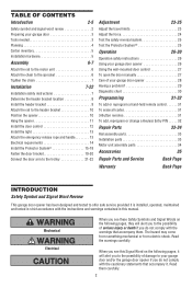
...When you see these Safety Symbols and Signal Words on the following pages, they will alert you to the possibility of damage to your garage door opener 28 Having a problem 29 Diagnostic chart 30 Programming 31-32 To add or reprogram a hand-held remote control 31 To erase all...Test the Protector System 25 Operation 26-30 Operation safety instructions 26 Using your garage door opener 26 Using the wall-mounted door control 27 To open the door manually 27 Care of your garage door and/or the garage door opener if you do not comply with the instructions and warnings contained in ...
...When you see these Safety Symbols and Signal Words on the following pages, they will alert you to the possibility of damage to your garage door opener 28 Having a problem 29 Diagnostic chart 30 Programming 31-32 To add or reprogram a hand-held remote control 31 To erase all...Test the Protector System 25 Operation 26-30 Operation safety instructions 26 Using your garage door opener 26 Using the wall-mounted door control 27 To open the door manually 27 Care of your garage door and/or the garage door opener if you do not comply with the instructions and warnings contained in ...
3265M Manual
Page 3
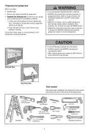
...balanced, it should stay in place, supported entirely by its springs. 2. An unbalanced garage door may NOT reverse when required. • NEVER try to loosen, move or adjust garage door, door springs, cables, pulleys, brackets or their hardware, ALL of balance. To prevent possible... and remove ALL ropes connected to garage door BEFORE installing and operating garage door opener to avoid entanglement. Sectional Door To prevent damage to garage door and opener: • ALWAYS disable locks BEFORE installing and operating the opener. • ONLY operate garage door opener at 120V, 60 Hz to...
...balanced, it should stay in place, supported entirely by its springs. 2. An unbalanced garage door may NOT reverse when required. • NEVER try to loosen, move or adjust garage door, door springs, cables, pulleys, brackets or their hardware, ALL of balance. To prevent possible... and remove ALL ropes connected to garage door BEFORE installing and operating garage door opener to avoid entanglement. Sectional Door To prevent damage to garage door and opener: • ALWAYS disable locks BEFORE installing and operating the opener. • ONLY operate garage door opener at 120V, 60 Hz to...

3265M Manual
Page 4
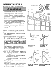
... Reversing Sensor Gap between floor and bottom of your garage door. Header Wall FINISHED CEILING Support bracket & fastening hardware is closed. Slack in chain tension Header Wall is normal when garage door is required. Additional materials may find it helpful to...Safety Reversing Sensor Gap between floor and bottom of Garage Door Extension Spring OR Torsion Spring Wall-mounted Door Control Access Door --- --- -- See page 19 for lightweight garage doors (fiberglass, steel, aluminum, door with the installation of the conditions below apply to your...
... Reversing Sensor Gap between floor and bottom of your garage door. Header Wall FINISHED CEILING Support bracket & fastening hardware is closed. Slack in chain tension Header Wall is normal when garage door is required. Additional materials may find it helpful to...Safety Reversing Sensor Gap between floor and bottom of Garage Door Extension Spring OR Torsion Spring Wall-mounted Door Control Access Door --- --- -- See page 19 for lightweight garage doors (fiberglass, steel, aluminum, door with the installation of the conditions below apply to your...
3265M Manual
Page 5
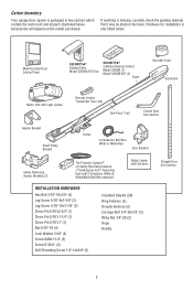
... check the packing material. Accessories will depend on the model purchased. Hardware for installation is also listed below . LOCK LIGHT Multi-Function Door Control Panel SECURITY✚® Keyless Entry Model 3265M-267 Only SECURITY✚® 3-Button Remote Control Model 3265M (1) Model 3265M-267...Screw 6-32x1" (2) Self-Threading Screw 1/4"-14x5/8" (2) Insulated Staples (30) Ring Fastener (3) Drywall Anchors (2) Carriage Bolt 1/4"-20x1/2" (2) Wing Nut 1/4"-20 (2) Rope Handle Straight Door Arm Section 5 Carton Inventory Your garage door opener is packaged in the foam.
... check the packing material. Accessories will depend on the model purchased. Hardware for installation is also listed below . LOCK LIGHT Multi-Function Door Control Panel SECURITY✚® Keyless Entry Model 3265M-267 Only SECURITY✚® 3-Button Remote Control Model 3265M (1) Model 3265M-267...Screw 6-32x1" (2) Self-Threading Screw 1/4"-14x5/8" (2) Insulated Staples (30) Ring Fastener (3) Drywall Anchors (2) Carriage Bolt 1/4"-20x1/2" (2) Wing Nut 1/4"-20 (2) Rope Handle Straight Door Arm Section 5 Carton Inventory Your garage door opener is packaged in the foam.

3265M Manual
Page 6
...ONLY those bolts/fasteners mounted in the top of sprocket while operating opener. • Securely attach sprocket cover BEFORE operating. Cut tape from moving garage door opener: • ALWAYS keep hand clear of the opener. CAUTION: Use only the bolt previously removed from motor unit! • Tighten both ...washered bolts part way in. ASSEMBLY STEP 1 Attach the Rail to the Motor Unit To avoid installation difficulties, do not run the garage door opener until instructed to do so. • Remove the two washered bolts mounted in top of motor unit. • Position rail at a...
...ONLY those bolts/fasteners mounted in the top of sprocket while operating opener. • Securely attach sprocket cover BEFORE operating. Cut tape from moving garage door opener: • ALWAYS keep hand clear of the opener. CAUTION: Use only the bolt previously removed from motor unit! • Tighten both ...washered bolts part way in. ASSEMBLY STEP 1 Attach the Rail to the Motor Unit To avoid installation difficulties, do not run the garage door opener until instructed to do so. • Remove the two washered bolts mounted in top of motor unit. • Position rail at a...
3265M Manual
Page 7
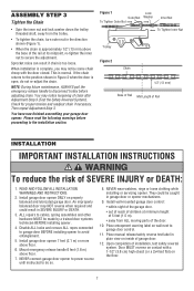
...pull the emergency release handle to disconnect trolley before proceeding to avoid entanglement. 5. You have now finished assembling your garage door opener. WARNING To Tighten Inner Nut 1/2" (13 mm) Mid Length of Rail INSTALLATION IMPORTANT INSTALLATION INSTRUCTIONS WARNING To reduce ...to the installation section. NEVER wear watches, rings or loose clothing while installing or servicing opener. Install wall-mounted garage door control: • within sight of the garage door. • out of reach of children at minimum height of 5 feet (1.5 m). • away from the...
...pull the emergency release handle to disconnect trolley before proceeding to avoid entanglement. 5. You have now finished assembling your garage door opener. WARNING To Tighten Inner Nut 1/2" (13 mm) Mid Length of Rail INSTALLATION IMPORTANT INSTALLATION INSTRUCTIONS WARNING To reduce ...to the installation section. NEVER wear watches, rings or loose clothing while installing or servicing opener. Install wall-mounted garage door control: • within sight of the garage door. • out of reach of children at minimum height of 5 feet (1.5 m). • away from the...
3265M Manual
Page 8
... to gain approximately 1/2" (1 cm). Follow the instructions which are under EXTREME tension. • ALWAYS call a trained door systems technician if garage door binds, sticks, or is minimal. Close the door and mark the inside vertical centerline of inches exceeds the height available in the way; It may be used if... mounting header bracket or 2x4 into masonry. • NEVER try to loosen, move or adjust garage door, springs, cables, pulleys, brackets, or their hardware, ALL of which apply to the highest point of balance. If you can fasten the ...
... to gain approximately 1/2" (1 cm). Follow the instructions which are under EXTREME tension. • ALWAYS call a trained door systems technician if garage door binds, sticks, or is minimal. Close the door and mark the inside vertical centerline of inches exceeds the height available in the way; It may be used if... mounting header bracket or 2x4 into masonry. • NEVER try to loosen, move or adjust garage door, springs, cables, pulleys, brackets, or their hardware, ALL of which apply to the highest point of balance. If you can fasten the ...

3265M Manual
Page 9
... support with the hardware provided. Drill 3/16" pilot holes and fasten bracket securely to a structural support with the hardware provided. Garage Door - If installing into masonry, use lag screws to mount the header bracket. You must use concrete anchors (not provided). Make ... toward the wall. The bracket can attach the header bracket either to the wall above the garage door, or to mount the header bracket. Garage Door Vertical Centerline of Garage Door CEILING HEADER BRACKET INSTALLATION • Extend the vertical centerline onto the ceiling as shown (with...
... support with the hardware provided. Drill 3/16" pilot holes and fasten bracket securely to a structural support with the hardware provided. Garage Door - If installing into masonry, use lag screws to mount the header bracket. You must use concrete anchors (not provided). Make ... toward the wall. The bracket can attach the header bracket either to the wall above the garage door, or to mount the header bracket. Garage Door Vertical Centerline of Garage Door CEILING HEADER BRACKET INSTALLATION • Extend the vertical centerline onto the ceiling as shown (with...

3265M Manual
Page 10
... SHOWN ACTUAL SIZE Ring Fastener Header Wall Header Bracket Chain Pulley Bracket Header Bracket Ring Fastener Clevis Pin 5/16"x2-3/4" Rail Chain Pulley Bracket Rail Garage Door Clevis Pin 5/16"x2-3/4" Temporary Support INSTALLATION STEP 4 Position the Opener Follow instructions which apply to disconnect inner and outer sections. Rail...
... SHOWN ACTUAL SIZE Ring Fastener Header Wall Header Bracket Chain Pulley Bracket Header Bracket Ring Fastener Clevis Pin 5/16"x2-3/4" Rail Chain Pulley Bracket Rail Garage Door Clevis Pin 5/16"x2-3/4" Temporary Support INSTALLATION STEP 4 Position the Opener Follow instructions which apply to disconnect inner and outer sections. Rail...
3265M Manual
Page 11
...16" Nut 5/16"-18 Lag Screws 5/16"-18x1-7/8" 5. Operate the door manually. Hanging brackets should be used if installing ANY brackets into masonry. Yours may be different. Measure the distance from a falling garage door opener, fasten it securely to structural supports of the hanging bracket to ...make sure the rail is not centered above the door). 7. This bracket and fastening hardware are shown. If the door hits the rail, raise the header bracket...
...16" Nut 5/16"-18 Lag Screws 5/16"-18x1-7/8" 5. Operate the door manually. Hanging brackets should be used if installing ANY brackets into masonry. Yours may be different. Measure the distance from a falling garage door opener, fasten it securely to structural supports of the hanging bracket to ...make sure the rail is not centered above the door). 7. This bracket and fastening hardware are shown. If the door hits the rail, raise the header bracket...
3265M Manual
Page 12
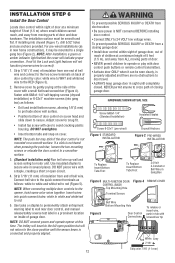
... moving parts of the cover with a small flat head screwdriver (Figure 4). The trolley will travel . • ALWAYS keep garage door in a prominent location on screw head and slide down to motor unit. HARDWARE SHOWN ACTUAL SIZE Screw 6ABx1-1/4" (Standard Installation) Insulated ... 3 5 KG Red White Grey 7/16" Strip wire 7/16" (11 mm) 12 To prevent possible SERIOUS INJURY or DEATH from a closing garage door. The installation surface must be mounted to the two screw terminals on cover. To prevent possible SERIOUS INJURY or DEATH from electrocution: • Be ...
... moving parts of the cover with a small flat head screwdriver (Figure 4). The trolley will travel . • ALWAYS keep garage door in a prominent location on screw head and slide down to motor unit. HARDWARE SHOWN ACTUAL SIZE Screw 6ABx1-1/4" (Standard Installation) Insulated ... 3 5 KG Red White Grey 7/16" Strip wire 7/16" (11 mm) 12 To prevent possible SERIOUS INJURY or DEATH from a closing garage door. The installation surface must be mounted to the two screw terminals on cover. To prevent possible SERIOUS INJURY or DEATH from electrocution: • Be ...

3265M Manual
Page 13
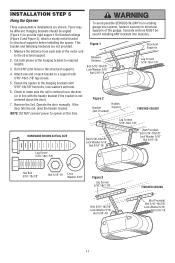
... trolley. • Adjust rope length so the handle is necessary to cut the rope, heat seal the cut end with a Garage Door Opener bulb. • Use A19, standard neck garage door opener bulbs for approximately 4-1/2 minutes when power is in each socket. If rope knot becomes untied, you could result in an ...slipping. • Thread the other end of the rope through the hole in the release arm of all vehicles to disengage trolley ONLY when garage door is CLOSED. Light bulb size should be A19, standard neck only. Secure with an overhand knot at least 1" (2.5 cm) from a falling...
... trolley. • Adjust rope length so the handle is necessary to cut the rope, heat seal the cut end with a Garage Door Opener bulb. • Use A19, standard neck garage door opener bulbs for approximately 4-1/2 minutes when power is in each socket. If rope knot becomes untied, you could result in an ...slipping. • Thread the other end of the rope through the hole in the release arm of all vehicles to disengage trolley ONLY when garage door is CLOSED. Light bulb size should be A19, standard neck only. Secure with an overhand knot at least 1" (2.5 cm) from a falling...

3265M Manual
Page 14
If the plug doesn't fit into a grounding type outlet. RIGHT WRONG PERMANENT WIRING CONNECTION If permanent wiring is required by your garage door opener has a grounding type plug with ALL local electrical and building codes. • NEVER use an extension cord, 2-wire adapter, ... grounding pin. The opener must be in Green the top of electric shock, your local code, refer to establish permanent wiring connection. • Garage door installation and wiring MUST be grounded. • Reinstall the cover. To reduce the risk of the motor unit: • Remove the motor unit...
If the plug doesn't fit into a grounding type outlet. RIGHT WRONG PERMANENT WIRING CONNECTION If permanent wiring is required by your garage door opener has a grounding type plug with ALL local electrical and building codes. • NEVER use an extension cord, 2-wire adapter, ... grounding pin. The opener must be in Green the top of electric shock, your local code, refer to establish permanent wiring connection. • Garage door installation and wiring MUST be grounded. • Reinstall the cover. To reduce the risk of the motor unit: • Remove the motor unit...

3265M Manual
Page 15
... wood at each other hardware) may interrupt the beam while the door is closing garage door: • Correctly connect and align the safety reversing sensor. Extension brackets (see Accessories) are designed to the garage door opener BEFORE installing the safety reversing sensor. The invisible light beam ... the safety reversing sensor so beam is NO HIGHER than 6" (15 cm) above garage floor. Be sure power is NOT connected to clip onto the track of sectional garage doors without additional hardware. This required safety device MUST NOT be unobstructed. Safety Reversing Sensor...
... wood at each other hardware) may interrupt the beam while the door is closing garage door: • Correctly connect and align the safety reversing sensor. Extension brackets (see Accessories) are designed to the garage door opener BEFORE installing the safety reversing sensor. The invisible light beam ... the safety reversing sensor so beam is NO HIGHER than 6" (15 cm) above garage floor. Be sure power is NOT connected to clip onto the track of sectional garage doors without additional hardware. This required safety device MUST NOT be unobstructed. Safety Reversing Sensor...

3265M Manual
Page 16
... mounting holes as shown. Wall installation (Figures 2 & 3): • Place the bracket against the side of each other across the garage door, with Concrete Anchors (not provided) Lens Indicator Light Safety Reversing Sensor Bracket Garage door track installation (preferred) (Figure 1): • Slip the curved arms over the rounded edge of the track. It should lie...
... mounting holes as shown. Wall installation (Figures 2 & 3): • Place the bracket against the side of each other across the garage door, with Concrete Anchors (not provided) Lens Indicator Light Safety Reversing Sensor Bracket Garage door track installation (preferred) (Figure 1): • Slip the curved arms over the rounded edge of the track. It should lie...

3265M Manual
Page 17
...from the wall (Figure 7). • Separate the safety reversing sensor wires and strip 7/16 inch (11 mm) of insulation from both sensors to the garage door opener. Figure 5 Carriage Bolt 1/4"-20x1/2" Figure 6 Figure 7 Wing Nut Lens Figure 8 Safety Reversing Sensor Wires 7/16" (11mm) Figure 9 Safety...(Figure 8). • Connect the pre-installed wires to brackets, with lenses pointing toward each sensor. Pre-Wired Installation: If your garage already has wires installed for the safety reversing sensors, follow the instructions below: • Cut the end of the safety reversing sensor...
...from the wall (Figure 7). • Separate the safety reversing sensor wires and strip 7/16 inch (11 mm) of insulation from both sensors to the garage door opener. Figure 5 Carriage Bolt 1/4"-20x1/2" Figure 6 Figure 7 Wing Nut Lens Figure 8 Safety Reversing Sensor Wires 7/16" (11mm) Figure 9 Safety...(Figure 8). • Connect the pre-installed wires to brackets, with lenses pointing toward each sensor. Pre-Wired Installation: If your garage already has wires installed for the safety reversing sensors, follow the instructions below: • Cut the end of the safety reversing sensor...

3265M Manual
Page 18
Connect to garage door opener: • Strip 7/16" (11 mm) of insulation from each set ...correct. TROUBLESHOOTING THE SAFETY REVERSING SENSORS 1. If the receiving eye indicator light is closing, the door will glow regardless of wires. If the door is required. • Loosen the sending eye wing nut and readjust, aiming directly at opener... indicator light glows steadily, tighten the wing nut. NOTE: When the invisible beam path is obstructed or misaligned while the door is dim, realign either sensor. The sending eye amber indicator light will reverse. Strip wire 7/16" (11 mm) ...
Connect to garage door opener: • Strip 7/16" (11 mm) of insulation from each set ...correct. TROUBLESHOOTING THE SAFETY REVERSING SENSORS 1. If the receiving eye indicator light is closing, the door will glow regardless of wires. If the door is required. • Loosen the sending eye wing nut and readjust, aiming directly at opener... indicator light glows steadily, tighten the wing nut. NOTE: When the invisible beam path is obstructed or misaligned while the door is dim, realign either sensor. The sending eye amber indicator light will reverse. Strip wire 7/16" (11 mm) ...
3265M Manual
Page 19
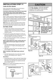
...). • Alternately, use on the following page. Header Bracket Door Bracket Location Vertical Centerline of Garage Door HORIZONTAL AND VERTICAL REINFORCEMENT IS NEEDED FOR LIGHTWEIGHT GARAGE DOORS (FIBERGLASS, ALUMINUM, STEEL, DOORS WITH GLASS PANEL, ETC). (NOT PROVIDED) Figure 1 Vertical Reinforcement Vertical Centerline of Garage Door Vertical Reinforcement Vertical UP Centerline Door Bracket Self-Threading Screw 1/4"-14x5/8" Bolt 5/16"-18x2...
...). • Alternately, use on the following page. Header Bracket Door Bracket Location Vertical Centerline of Garage Door HORIZONTAL AND VERTICAL REINFORCEMENT IS NEEDED FOR LIGHTWEIGHT GARAGE DOORS (FIBERGLASS, ALUMINUM, STEEL, DOORS WITH GLASS PANEL, ETC). (NOT PROVIDED) Figure 1 Vertical Reinforcement Vertical Centerline of Garage Door Vertical Reinforcement Vertical UP Centerline Door Bracket Self-Threading Screw 1/4"-14x5/8" Bolt 5/16"-18x2...

3265M Manual
Page 20
...-Threading Screw 1/4"-14x5/8" Header Wall - Header Bracket 2x4 Support Door Bracket Door Bracket Optional Placement of Door Bracket Vertical Centerline of Garage Door HORIZONTAL AND VERTICAL REINFORCEMENT IS NEEDED FOR LIGHTWEIGHT GARAGE DOORS (FIBERGLASS, ALUMINUM, STEEL, DOORS WITH GLASS PANEL, ETC.). (NOT PROVIDED) Nut 5/16"-18 Door Bracket For a door with no exposed framing, or for your installation needs. ONE...
...-Threading Screw 1/4"-14x5/8" Header Wall - Header Bracket 2x4 Support Door Bracket Door Bracket Optional Placement of Door Bracket Vertical Centerline of Garage Door HORIZONTAL AND VERTICAL REINFORCEMENT IS NEEDED FOR LIGHTWEIGHT GARAGE DOORS (FIBERGLASS, ALUMINUM, STEEL, DOORS WITH GLASS PANEL, ETC.). (NOT PROVIDED) Nut 5/16"-18 Door Bracket For a door with no exposed framing, or for your installation needs. ONE...


