

3595 Elite Series Manual
Page 1
The Chamberlain Group, Inc. 845 Larch Avenue Elmhurst, Illinois 60126-1196 www.liftmaster.com ® GARAGE DOOR OPENER Model 3595 3/4 HP For Residential Use Install on the left side panel of your opener. Owner's Manual ■ Please read this manual and the enclosed safety materials ... operation. ■ The model number label is located under the light lens on Sectional Doors ONLY THIS OPERATOR IS INTENDED FOR USE ONLY WITH I-BEAM RAILS.
The Chamberlain Group, Inc. 845 Larch Avenue Elmhurst, Illinois 60126-1196 www.liftmaster.com ® GARAGE DOOR OPENER Model 3595 3/4 HP For Residential Use Install on the left side panel of your opener. Owner's Manual ■ Please read this manual and the enclosed safety materials ... operation. ■ The model number label is located under the light lens on Sectional Doors ONLY THIS OPERATOR IS INTENDED FOR USE ONLY WITH I-BEAM RAILS.

3595 Elite Series Manual
Page 2
...and signal word review 2 Preparing your garage door 3 Tools needed 3 Planning 4 Carton inventory 5 Hardware inventory 5 Assembly 6-7 Attach the rail to the motor unit 6 Attach the chain spreader 6 Attach chassis support bracket 6 Tighten the chain 7 Installation 7-19 Installation safety instructions ...7 Determine the header bracket location 8 Install the header bracket 9 Attach the rail to the header bracket 10 Position the opener 10 Hang the opener 11 Install the door control 12 Install the light...
...and signal word review 2 Preparing your garage door 3 Tools needed 3 Planning 4 Carton inventory 5 Hardware inventory 5 Assembly 6-7 Attach the rail to the motor unit 6 Attach the chain spreader 6 Attach chassis support bracket 6 Tighten the chain 7 Installation 7-19 Installation safety instructions ...7 Determine the header bracket location 8 Install the header bracket 9 Attach the rail to the header bracket 10 Position the opener 10 Hang the opener 11 Install the door control 12 Install the light...

3595 Elite Series Manual
Page 5
...Visor Clip CEILING MOUNT ONLY UP Chassis Support Bracket Header Bracket Chain Motor Unit With Light Lenses Chain Spreader Door Bracket Rail 2 Conductor Bell Wire White & White/Red Chain Pulley Bracket Trolley Safety Sensor Bracket (2) Curved Door Arm Section The ... Washered Bolt 5/16"-18x1/2" (2) Hex Bolt 1/4"-20x5/8" (4) Hex Screws 8-32x1" (2) Screw #8-32x3/8" Insulated Staples (30) Ring Fastener (3) Drywall Anchors (2) Rail Grease Carriage Bolt 1/4"-20x1/2" (2) Wing Nut 1/4"-20 (2) Lock Nut 1/4"-20 Lag Screw 1/4x1-1/2" (4) Rope Handle 5 Straight Door Arm Section contain the motor ...
...Visor Clip CEILING MOUNT ONLY UP Chassis Support Bracket Header Bracket Chain Motor Unit With Light Lenses Chain Spreader Door Bracket Rail 2 Conductor Bell Wire White & White/Red Chain Pulley Bracket Trolley Safety Sensor Bracket (2) Curved Door Arm Section The ... Washered Bolt 5/16"-18x1/2" (2) Hex Bolt 1/4"-20x5/8" (4) Hex Screws 8-32x1" (2) Screw #8-32x3/8" Insulated Staples (30) Ring Fastener (3) Drywall Anchors (2) Rail Grease Carriage Bolt 1/4"-20x1/2" (2) Wing Nut 1/4"-20 (2) Lock Nut 1/4"-20 Lag Screw 1/4x1-1/2" (4) Rope Handle 5 Straight Door Arm Section contain the motor ...
3595 Elite Series Manual
Page 6
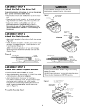
...(Figure 3). To avoid possible SERIOUS INJURY to fingers from the top of the motor unit. • Place rail onto the bolt mounted on the unit. • Attach the bracket to the rail with Carriage House Doors and the 8-tooth sprocket is for use bolts/fasteners mounted in the bracket. NOTE: The... in the top of the opener. Proceed to opener, ONLY use with the washered bolt and lock nut previously removed. ASSEMBLY STEP 1 Attach the Rail to the Motor Unit To avoid installation difficulties, do not run the garage door opener until instructed to do so. • Remove the bolt and...
...(Figure 3). To avoid possible SERIOUS INJURY to fingers from the top of the motor unit. • Place rail onto the bolt mounted on the unit. • Attach the bracket to the rail with Carriage House Doors and the 8-tooth sprocket is for use bolts/fasteners mounted in the bracket. NOTE: The... in the top of the opener. Proceed to opener, ONLY use with the washered bolt and lock nut previously removed. ASSEMBLY STEP 1 Attach the Rail to the Motor Unit To avoid installation difficulties, do not run the garage door opener until instructed to do so. • Remove the bolt and...

3595 Elite Series Manual
Page 7
... at minimum height of 5 feet (1.5 m). • away from twisting. • When the chain is approximately 1/2" (13 mm) above the base of the rail at its midpoint, re-tighten the inner nut to garage door control. 11. Door MUST reverse on contact with the door closed. Trolley Chain Base...manual release/safety reverse test label in the direction shown. Install garage door opener only on inside of garage door. 12. Upon completion of Rail WARNING You have now finished assembling your garage door opener. As you may not reverse when required and could be made by a trained door ...
... at minimum height of 5 feet (1.5 m). • away from twisting. • When the chain is approximately 1/2" (13 mm) above the base of the rail at its midpoint, re-tighten the inner nut to garage door control. 11. Door MUST reverse on contact with the door closed. Trolley Chain Base...manual release/safety reverse test label in the direction shown. Install garage door opener only on inside of garage door. 12. Upon completion of Rail WARNING You have now finished assembling your garage door opener. As you may not reverse when required and could be made by a trained door ...
3595 Elite Series Manual
Page 10
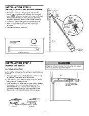
... Ring Fastener Clevis Pin 5/16"x2-3/4" Header Wall Header Bracket Chain Pulley Bracket Header Bracket Ring Fastener Clevis Pin 5/16"x2-3/4" Chain Pulley Bracket Rail Garage Door Temporary Support INSTALLATION STEP 4 Position the Opener SECTIONAL DOOR ONLY A 2x4 laid flat is used to determine the correct mounting height from... Step 12 is not tall enough. • Open the door all the way and place a 2x4 laid flat on the top section beneath the rail. • If the top section or panel hits the trolley when you 'll need help . Slide the outer trolley toward the motor unit. ...
... Ring Fastener Clevis Pin 5/16"x2-3/4" Header Wall Header Bracket Chain Pulley Bracket Header Bracket Ring Fastener Clevis Pin 5/16"x2-3/4" Chain Pulley Bracket Rail Garage Door Temporary Support INSTALLATION STEP 4 Position the Opener SECTIONAL DOOR ONLY A 2x4 laid flat is used to determine the correct mounting height from... Step 12 is not tall enough. • Open the door all the way and place a 2x4 laid flat on the top section beneath the rail. • If the top section or panel hits the trolley when you 'll need help . Slide the outer trolley toward the motor unit. ...

3595 Elite Series Manual
Page 11
... the door (or in the structural supports. 4. Operate the door manually. To avoid possible SERIOUS INJURY from each bracket to the hanging brackets with rail grease. Check to required lengths. 3. Remove the 2x4. Figure 1 Measure Distance Structural Supports Lag Screws 5/16"-18x1-7/8" Bolt 5/16"-18x7/8" Lock Washer...Bolt 5/16"-18x7/8" Lock Washer 5/16" Nut 5/16"-18 11 If the door hits the rail, raise the header bracket. 8. Yours may be different. Attach one end of each side of the rail surface where the trolley slides with 5/16"-18x7/8" hex bolts, lock washers and nuts. 6. ...
... the door (or in the structural supports. 4. Operate the door manually. To avoid possible SERIOUS INJURY from each bracket to the hanging brackets with rail grease. Check to required lengths. 3. Remove the 2x4. Figure 1 Measure Distance Structural Supports Lag Screws 5/16"-18x1-7/8" Bolt 5/16"-18x7/8" Lock Washer...Bolt 5/16"-18x7/8" Lock Washer 5/16" Nut 5/16"-18 11 If the door hits the rail, raise the header bracket. 8. Yours may be different. Attach one end of each side of the rail surface where the trolley slides with 5/16"-18x7/8" hex bolts, lock washers and nuts. 6. ...
3595 Elite Series Manual
Page 31
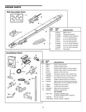
.... 4A1008 41A2780 41A3489 3707CH 3708CH 3710CH 41D3484 41D3483 41D3485 83A11-2 DESCRIPTION Master link kit Chain pulley bracket Complete trolley assembly 7' (2.1 m) Rail assembly 8' (2.4 m) Rail assembly 10' (3 m) Rail assembly 7' (2.1 m) Chain assembly 8' (2.4 m) Chain assembly 10' (3 m) Chain assembly Rail grease KEY PART NO. Spanish 31 NO. DESCRIPTION 1 398LM Smart Control Panel™ 2 373P 3-button remote control 3 10A19 3V2016...
.... 4A1008 41A2780 41A3489 3707CH 3708CH 3710CH 41D3484 41D3483 41D3485 83A11-2 DESCRIPTION Master link kit Chain pulley bracket Complete trolley assembly 7' (2.1 m) Rail assembly 8' (2.4 m) Rail assembly 10' (3 m) Rail assembly 7' (2.1 m) Chain assembly 8' (2.4 m) Chain assembly 10' (3 m) Chain assembly Rail grease KEY PART NO. Spanish 31 NO. DESCRIPTION 1 398LM Smart Control Panel™ 2 373P 3-button remote control 3 10A19 3V2016...


