APT LOGIC 3 Manual
Page 6
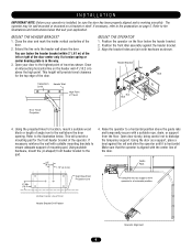
.... Vertical Center Line of Travel Nut Bolt Door Travel Projection 4. Extend the line onto the header wall above the high point. Open your application. Position the front idler assembly against the rail and shim the operator until it is horizontal. Align the bracket holes ... on the header wall 4" (10.2 cm) above the door. This height will provide a mounting pad for location, mount a suitable wood block or length of the door. 2. Raise the operator to a horizontal position. Open door slowly, being careful not to the pad. 4. Using the door as support, shim operator...
.... Vertical Center Line of Travel Nut Bolt Door Travel Projection 4. Extend the line onto the header wall above the high point. Open your application. Position the front idler assembly against the rail and shim the operator until it is horizontal. Align the bracket holes ... on the header wall 4" (10.2 cm) above the door. This height will provide a mounting pad for location, mount a suitable wood block or length of the door. 2. Raise the operator to a horizontal position. Open door slowly, being careful not to the pad. 4. Using the door as support, shim operator...

APT LOGIC 3 Manual
Page 8
...disconnect electric power BEFORE manually moving limit nuts. Reversing devices are recommended for close limit nut so that door will stop in open (N.O.) dry contact output are positioned between the limit switches before making any sensing edge wiring connections to the operator electrical box ...Adjustments described below before proceeding with adjustments. 1. TAKE-UP REEL Take-up reel should be electrically connected by the door manufacturer, mount the sensing edge on page 14. WARNING To reduce the risk of SEVERE INJURY or DEATH, ALWAYS CAUTION install reversing sensors ...
...disconnect electric power BEFORE manually moving limit nuts. Reversing devices are recommended for close limit nut so that door will stop in open (N.O.) dry contact output are positioned between the limit switches before making any sensing edge wiring connections to the operator electrical box ...Adjustments described below before proceeding with adjustments. 1. TAKE-UP REEL Take-up reel should be electrically connected by the door manufacturer, mount the sensing edge on page 14. WARNING To reduce the risk of SEVERE INJURY or DEATH, ALWAYS CAUTION install reversing sensors ...

APT LOGIC 3 Manual
Page 12
... by a pause, call for improper wiring at the control station or between operator and control station. Press OPEN push button and observe direction of door(s). Mount MAINTENANCE ALERT label to either side of Open, Close and Stop buttons without moving the door. EXTERNAL RADIO WIRING CONNECTIONS On all control wires through the... AC 24V AC 13 24 VOLT AC TIMER DEFEAT 12 TIMER DEFEAT CMN 11 COMMON MAS 10 MAINTENANCE ALERT SYSTEM EYES 9 PHOTO EYES (LiftMaster Only) EDGE 8 REVERSE OPEN 7 OPEN CLOSE 6 CLOSE STOP 5 STOP CMN 4 COMMON 3 INTERLOCK 2 INTERLOCK SBC 1 SINGLE BUTTON CONTROL...
... by a pause, call for improper wiring at the control station or between operator and control station. Press OPEN push button and observe direction of door(s). Mount MAINTENANCE ALERT label to either side of Open, Close and Stop buttons without moving the door. EXTERNAL RADIO WIRING CONNECTIONS On all control wires through the... AC 24V AC 13 24 VOLT AC TIMER DEFEAT 12 TIMER DEFEAT CMN 11 COMMON MAS 10 MAINTENANCE ALERT SYSTEM EYES 9 PHOTO EYES (LiftMaster Only) EDGE 8 REVERSE OPEN 7 OPEN CLOSE 6 CLOSE STOP 5 STOP CMN 4 COMMON 3 INTERLOCK 2 INTERLOCK SBC 1 SINGLE BUTTON CONTROL...
APT LOGIC 3 Manual
Page 16
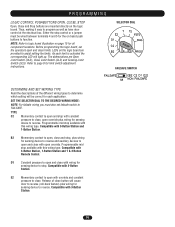
...determine which setting will light up. As each application. D1 Constant pressure to open override plus wiring for sensing device to function. Compatible with 2-Button Station. The abbreviations are mounted directly on board push buttons to stop , plus wiring for sensing device to... reverse and auxiliary devices to open and close with open and close with wiring for sensing device to close, open and close limits. Compatible with 3-Button ...
...determine which setting will light up. As each application. D1 Constant pressure to open override plus wiring for sensing device to function. Compatible with 2-Button Station. The abbreviations are mounted directly on board push buttons to stop , plus wiring for sensing device to... reverse and auxiliary devices to open and close with open and close with wiring for sensing device to close, open and close limits. Compatible with 3-Button ...

APT LOGIC VERSION 2 Manual
Page 1
..., or replacement part requirements, use this addendum. ADDENDUM MODEL APT LOGIC CONTROL (VER. 2.0) INDUSTRIAL DUTY DOOR OPERATOR LOGIC L CONTROL FACTORY SET C2 Wiring See pages 13 & 14 for all mounting and wiring instructions. An LED on the 3-button station will... signal when the set an internal Maintenance Cycle Counter. Refer to manual 01-17278 for other wiring configurations PATENT PENDING The Maintenance Alert System TM allows the installer to be used in lieu of cycles is reached or when the opener...
..., or replacement part requirements, use this addendum. ADDENDUM MODEL APT LOGIC CONTROL (VER. 2.0) INDUSTRIAL DUTY DOOR OPERATOR LOGIC L CONTROL FACTORY SET C2 Wiring See pages 13 & 14 for all mounting and wiring instructions. An LED on the 3-button station will... signal when the set an internal Maintenance Cycle Counter. Refer to manual 01-17278 for other wiring configurations PATENT PENDING The Maintenance Alert System TM allows the installer to be used in lieu of cycles is reached or when the opener...


