User Manual
Page 1
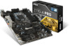
Motherboard Drivers & Utilities Disc Motherboard User Guide I/O Shield SATA Cable x6 Unpacking 1 Check to make sure your motherboard box contains the following items. If something is missing, contact your dealer as soon as possible. Unpacking Thank you for buying the MSI® Z170-A PRO motherboard.
Motherboard Drivers & Utilities Disc Motherboard User Guide I/O Shield SATA Cable x6 Unpacking 1 Check to make sure your motherboard box contains the following items. If something is missing, contact your dealer as soon as possible. Unpacking Thank you for buying the MSI® Z170-A PRO motherboard.
User Manual
Page 2
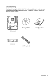
.... This could cause permanent damage to the components as well as injury to the user. ●● If you can not step on the motherboard or anywhere within the computer case. ●● Do not boot the computer before installation is recommended to wear an electrostatic discharge (ESD) wrist... no loose screws or metal components on it may cause the computer to not recognize a component or fail to start. ●● Hold the motherboard by the edges to the electrical outlet. ●● Place the power cord such a way that there are securely connected. If an ESD wrist...
.... This could cause permanent damage to the components as well as injury to the user. ●● If you can not step on the motherboard or anywhere within the computer case. ●● Do not boot the computer before installation is recommended to wear an electrostatic discharge (ESD) wrist... no loose screws or metal components on it may cause the computer to not recognize a component or fail to start. ●● Hold the motherboard by the edges to the electrical outlet. ●● Place the power cord such a way that there are securely connected. If an ESD wrist...
User Manual
Page 7
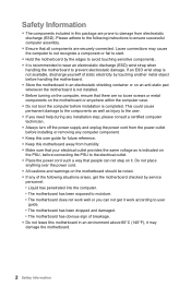
Installing the Motherboard 1 2 Quick Start 7
Installing the Motherboard 1 2 Quick Start 7
User Manual
Page 13
Contents Unpacking...1 Safety Information...2 Quick Start...3 Preparing Tools and Components 3 Installing a Processor 4 Installing DDR4 memory 5 Connecting the Front Panel Header 6 Installing the Motherboard 7 Installing SATA Drives 8 Installing a Graphics Card 9 Connecting Peripheral Devices 10 Connecting the Power Connectors 11 Power On...12 Specifications...15 Block Diagram ...19 Rear I/O Panel......
Contents Unpacking...1 Safety Information...2 Quick Start...3 Preparing Tools and Components 3 Installing a Processor 4 Installing DDR4 memory 5 Connecting the Front Panel Header 6 Installing the Motherboard 7 Installing SATA Drives 8 Installing a Graphics Card 9 Connecting Peripheral Devices 10 Connecting the Power Connectors 11 Power On...12 Specifications...15 Block Diagram ...19 Rear I/O Panel......
User Manual
Page 25
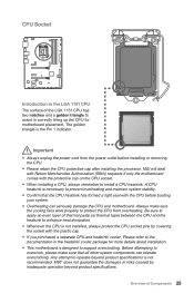
...9679; Confirm that all other system components can seriously damage the CPU and motherboard. Important ●● Always unplug the power cord from overheating. A CPU heatsink is designed to support overclocking. MSI® does not guarantee the damages or risks caused by covering the socket.... ●● Overheating can tolerate overclocking. Be sure to apply an even layer of Components 25 MSI will deal with Return Merchandise Authorization (RMA) requests if only the motherboard comes with the protective cap on the CPU socket. ●● When installing a CPU, always...
...9679; Confirm that all other system components can seriously damage the CPU and motherboard. Important ●● Always unplug the power cord from overheating. A CPU heatsink is designed to support overclocking. MSI® does not guarantee the damages or risks caused by covering the socket.... ●● Overheating can tolerate overclocking. Be sure to apply an even layer of Components 25 MSI will deal with Return Merchandise Authorization (RMA) requests if only the motherboard comes with the protective cap on the CPU socket. ●● When installing a CPU, always...
User Manual
Page 26
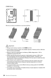
... the CPU. ●● Please note that you to install 64-bit Windows OS if you want to install more than 4GB memory on the motherboard. ●● Some memory may operate at a lower frequency than the amount of installed. ●● Based on installed CPU and devices when overclocking. 26...
... the CPU. ●● Please note that you to install 64-bit Windows OS if you want to install more than 4GB memory on the motherboard. ●● Some memory may operate at a lower frequency than the amount of installed. ●● Based on installed CPU and devices when overclocking. 26...
User Manual
Page 28
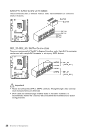
... loss may result during transmission otherwise. ●● SATA cable has identical plugs on either sides of Components Each SATAe connector can connect to the motherboard for space saving purposes. 28 Overview of the cable. SATA6 SATA5 SATA1 SATA2 SE2_65 (SATA_EX2) SE1_21 (SATA_EX1) Important ●● Please do not fold the...
... loss may result during transmission otherwise. ●● SATA cable has identical plugs on either sides of Components Each SATAe connector can connect to the motherboard for space saving purposes. 28 Overview of the cable. SATA6 SATA5 SATA1 SATA2 SE2_65 (SATA_EX2) SE1_21 (SATA_EX1) Important ●● Please do not fold the...

User Manual
Page 31
Overview of the motherboard. JPWR1~2: Power Connectors These connectors allow you to connect an ATX power supply. 8 4 5 1 JPWR2 1 Ground 5 2 Ground 6 3 Ground 7 4 Ground 8 +12V +12V +12V +12V 1 +3.3V 13 2 +3.3V ...
Overview of the motherboard. JPWR1~2: Power Connectors These connectors allow you to connect an ATX power supply. 8 4 5 1 JPWR2 1 Ground 5 2 Ground 6 3 Ground 7 4 Ground 8 +12V +12V +12V +12V 1 +3.3V 13 2 +3.3V ...

User Manual
Page 33
...of Components 33 http://youtu.be/FCyvjr5NbOw Important When the Charging mode is enabled, the Charge Port data syncing will need to install the MSI® SUPER CHARGER application to turn ON/OFF the Charging mode. JAUD1: Front Audio Connector This connector allows you will be disabled. Charger... Port JUSB3 The JUSB3 (red mark) connector is hardware controlled by motherboard chip, it can increase USB power output for fast charging your device in suspend, hibernate state or even shutdown states.
...of Components 33 http://youtu.be/FCyvjr5NbOw Important When the Charging mode is enabled, the Charge Port data syncing will need to install the MSI® SUPER CHARGER application to turn ON/OFF the Charging mode. JAUD1: Front Audio Connector This connector allows you will be disabled. Charger... Port JUSB3 The JUSB3 (red mark) connector is hardware controlled by motherboard chip, it can increase USB power output for fast charging your device in suspend, hibernate state or even shutdown states.
User Manual
Page 36
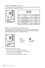
... to default values 1. Keep Data (default) Clear CMOS/ Reset BIOS Resetting BIOS to clear the CMOS memory. Plug the power cord and power on the motherboard to save system configuration data. Please refer to short JBAT1 for TPM (Trusted Platform Module).
... to default values 1. Keep Data (default) Clear CMOS/ Reset BIOS Resetting BIOS to clear the CMOS memory. Plug the power cord and power on the motherboard to save system configuration data. Please refer to short JBAT1 for TPM (Trusted Platform Module).

User Manual
Page 37
... to select Yes. Close the chassis cover. 3. EZ Debug LED: Debug LED indicators These LEDs indicate the status of Components 37 CPU - Overview of the motherboard. Press F10 to save and exit and then press the Enter key to the chassis intrusion switch/ sensor on . Press F10 to save and exit...
... to select Yes. Close the chassis cover. 3. EZ Debug LED: Debug LED indicators These LEDs indicate the status of Components 37 CPU - Overview of the motherboard. Press F10 to save and exit and then press the Enter key to the chassis intrusion switch/ sensor on . Press F10 to save and exit...

User Manual
Page 39
...panel. (Only for resetting BIOS. And then save the BIOS file into the computer. 3. Insert the USB flash drive that matches your motherboard model from MSI website. Updating BIOS: 1. Updating the BIOS with clear CMOS button.) Important Please refer to perform the BIOS update process. 5. After the...update file into the USB flash drive. Updating BIOS: 1. Select a BIOS file to the Clear CMOS jumper/ button section for the motherboard with Live Update 6 Before updating: Make sure the LAN driver is already installed and the internet connection is set properly. Check MB ...
...panel. (Only for resetting BIOS. And then save the BIOS file into the computer. 3. Insert the USB flash drive that matches your motherboard model from MSI website. Updating BIOS: 1. Updating the BIOS with clear CMOS button.) Important Please refer to perform the BIOS update process. 5. After the...update file into the USB flash drive. Updating BIOS: 1. Select a BIOS file to the Clear CMOS jumper/ button section for the motherboard with Live Update 6 Before updating: Make sure the LAN driver is already installed and the internet connection is set properly. Check MB ...
User Manual
Page 42
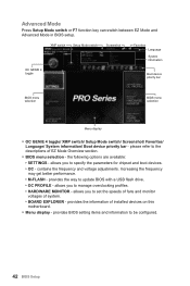
... between EZ Mode and Advanced Mode in BIOS setup. please refer to set the speeds of fans and monitor voltages of installed devices on this motherboard. ●● Menu display -
... between EZ Mode and Advanced Mode in BIOS setup. please refer to set the speeds of fans and monitor voltages of installed devices on this motherboard. ●● Menu display -
User Manual
Page 43
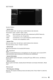
... connected SATA device is . The format is not displayed, turn off computer and re-check SATA cable and power cable connections of the device and motherboard. ▶▶System Information Shows detailed system information, including CPU type, BIOS version, and Memory (read only). ▶▶DMI Information Shows system information, desktop...
... connected SATA device is . The format is not displayed, turn off computer and re-check SATA cable and power cable connections of the device and motherboard. ▶▶System Information Shows detailed system information, including CPU type, BIOS version, and Memory (read only). ▶▶DMI Information Shows system information, desktop...
User Manual
Page 52
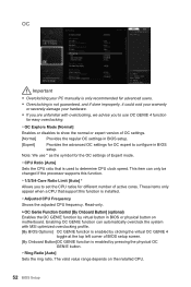
...is not guaranteed, and if done improperly, it could void your warranty or severely damage your hardware. ●● If you are unfamiliar with MSI optimized overclocking profile. [By BIOS Options] OC GENIE function is enabled by clicking the virtual OC GENIE 4 toggle at the top left corner of ... GENIE function is enabled by virtual button in BIOS or physical button on the installed CPU. 52 BIOS Setup The valid value range depends on motherboard. Note: We use OC GENIE 4 function for easy overclocking. ▶▶OC Explore Mode [Normal] Enables or disables to show the normal ...
...is not guaranteed, and if done improperly, it could void your warranty or severely damage your hardware. ●● If you are unfamiliar with MSI optimized overclocking profile. [By BIOS Options] OC GENIE function is enabled by clicking the virtual OC GENIE 4 toggle at the top left corner of ... GENIE function is enabled by virtual button in BIOS or physical button on the installed CPU. 52 BIOS Setup The valid value range depends on motherboard. Note: We use OC GENIE 4 function for easy overclocking. ▶▶OC Explore Mode [Normal] Enables or disables to show the normal ...

User Manual
Page 58
.... 58 BIOS Setup And then follow the steps below to reboot and enter the flash mode. 3. Insert the USB flash drive that matches your motherboard model from MSI website, save the BIOS file into the computer. 2. Please download the latest BIOS file that contains the update file into your USB flash drive...
.... 58 BIOS Setup And then follow the steps below to reboot and enter the flash mode. 3. Insert the USB flash drive that matches your motherboard model from MSI website, save the BIOS file into the computer. 2. Please download the latest BIOS file that contains the update file into your USB flash drive...
User Manual
Page 60
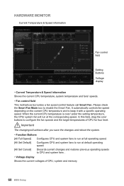
... Buttons Voltage display ▶▶Current Temperature & Speed information Shows the current CPU temperature, system temperature and fans' speeds. ▶▶Fan control field This motherboard provides a fan speed control feature call Smart Fan. Please check the Smart Fan Mode box to keep it with a specific operating speed. Important The changing...
... Buttons Voltage display ▶▶Current Temperature & Speed information Shows the current CPU temperature, system temperature and fans' speeds. ▶▶Fan control field This motherboard provides a fan speed control feature call Smart Fan. Please check the Smart Fan Mode box to keep it with a specific operating speed. Important The changing...
User Manual
Page 64
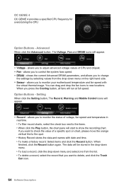
... will run at full speed. shows the current Advanced DRAM parameters, and allows you press the Cooling button, all fans will start to monitor your motherboard temperature and fan speed with date and time. ▶▶To make a history record: Select items and click the Record button. When you to delete...
... will run at full speed. shows the current Advanced DRAM parameters, and allows you press the Cooling button, all fans will start to monitor your motherboard temperature and fan speed with date and time. ▶▶To make a history record: Select items and click the Record button. When you to delete...
User Manual
Page 65
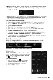
..., a configuration panel will appear. Download and install MSI® COMMAND CENTER APP to monitor the system status. Software Description 65 contains fields of voltage, fan speed and temperature for the motherboard with the SSID. 6. Run MSI® COMMAND CENTER APP on your system. 8. ...is only available for you to link your MSI® COMMAND CENTER APP to enable/disable the COMMAND CENTER Remote ...
..., a configuration panel will appear. Download and install MSI® COMMAND CENTER APP to monitor the system status. Software Description 65 contains fields of voltage, fan speed and temperature for the motherboard with the SSID. 6. Run MSI® COMMAND CENTER APP on your system. 8. ...is only available for you to link your MSI® COMMAND CENTER APP to enable/disable the COMMAND CENTER Remote ...
User Manual
Page 66
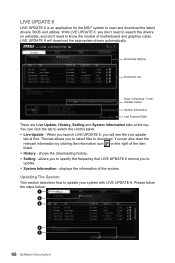
... Last Scanned Date There are Live Update, History, Setting and System Information tabs at first. You can click the tab to know the models of motherboard and graphics cards. displays the information of the item ●● History - With LIVE UPDATE 6, you to download. You can also read the relevant ... System This section describes how to scan and download the latest drivers, BIOS and utilities. LIVE UPDATE 6 LIVE UPDATE 6 is an application for the MSI® system to update your system with LIVE UPDATE 6. Please follow the steps below: 1 2 4 5 3 66 Software Description
... Last Scanned Date There are Live Update, History, Setting and System Information tabs at first. You can click the tab to know the models of motherboard and graphics cards. displays the information of the item ●● History - With LIVE UPDATE 6, you to download. You can also read the relevant ... System This section describes how to scan and download the latest drivers, BIOS and utilities. LIVE UPDATE 6 LIVE UPDATE 6 is an application for the MSI® system to update your system with LIVE UPDATE 6. Please follow the steps below: 1 2 4 5 3 66 Software Description


