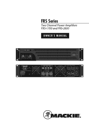
Owners Manual
Page 1
... NOT EXPOSE THIS EQUIPMENT TO RAIN OR MOISTURE. DO NOT REMOVE COVER. N'EXPOSEZ PAS CET ÉQUIPEMENT À LA PLUIE OU À L'HUMIDITÉ. REFER SERVICING TO QUALIFIED PERSONNEL. CHANNEL 2 BRIDGED CHANNEL 1 SPEAKER OUTPUTS Use only class 3 wiring PIN CH 2 1+ 1 PIN BRIDGED 1+ 2+ PIN CH 1 1+ 1 PIN CH 2 2+ 2 1+ 1 CH 1 INPUT FILTER SUBSONIC @ 30Hz CLIP LIMIT THRU AMP MODE THRU MONO STEREO BRIDGE
... NOT EXPOSE THIS EQUIPMENT TO RAIN OR MOISTURE. DO NOT REMOVE COVER. N'EXPOSEZ PAS CET ÉQUIPEMENT À LA PLUIE OU À L'HUMIDITÉ. REFER SERVICING TO QUALIFIED PERSONNEL. CHANNEL 2 BRIDGED CHANNEL 1 SPEAKER OUTPUTS Use only class 3 wiring PIN CH 2 1+ 1 PIN BRIDGED 1+ 2+ PIN CH 1 1+ 1 PIN CH 2 2+ 2 1+ 1 CH 1 INPUT FILTER SUBSONIC @ 30Hz CLIP LIMIT THRU AMP MODE THRU MONO STEREO BRIDGE
Owners Manual
Page 2
... designed to constitute a risk of Communications. FRS Series Amplifiers Important Safety Instructions 1. Follow all servicing to an authorized collection site for radio noise emissions from that may cause harmful interference to part 15 of time. 14. Do not use attachments/accessories specified by LOUD Technologies Inc. Install in any way, such as set out in the literature accompanying the appliance...
... designed to constitute a risk of Communications. FRS Series Amplifiers Important Safety Instructions 1. Follow all servicing to an authorized collection site for radio noise emissions from that may cause harmful interference to part 15 of time. 14. Do not use attachments/accessories specified by LOUD Technologies Inc. Install in any way, such as set out in the literature accompanying the appliance...
Owners Manual
Page 3
... of time. POWER 8 2. FAN VENTS 9 7. LEVEL CONTROLS 8 REAR PANEL FEATURES 9 5. SUBSONIC FILTER 10 GENERAL PRECAUTIONS 11 AC POWER REQUIREMENTS 11 THERMAL CONSIDERATIONS 11 RACK MOUNTING 11 MAINTENANCE 11 APPENDIX A: SERVICE INFORMATION 12 TROUBLESHOOTING 12 REPAIR 13 APPENDIX B: CONNECTIONS, MATH AND STUFF...... 14 XLR CONNECTORS 14 1/4" TRS PHONE PLUGS AND JACKS 14 1/4" TS PHONE PLUGS AND JACKS 14 NL4 JACKS 14 LOUDSPEAKER CABLE 14 LONGER LENGTHS 15 SPEAKER IMPEDANCES 15...
... of time. POWER 8 2. FAN VENTS 9 7. LEVEL CONTROLS 8 REAR PANEL FEATURES 9 5. SUBSONIC FILTER 10 GENERAL PRECAUTIONS 11 AC POWER REQUIREMENTS 11 THERMAL CONSIDERATIONS 11 RACK MOUNTING 11 MAINTENANCE 11 APPENDIX A: SERVICE INFORMATION 12 TROUBLESHOOTING 12 REPAIR 13 APPENDIX B: CONNECTIONS, MATH AND STUFF...... 14 XLR CONNECTORS 14 1/4" TRS PHONE PLUGS AND JACKS 14 1/4" TS PHONE PLUGS AND JACKS 14 NL4 JACKS 14 LOUDSPEAKER CABLE 14 LONGER LENGTHS 15 SPEAKER IMPEDANCES 15...
Owners Manual
Page 4
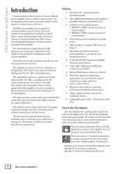
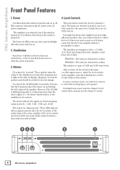
... 4 ohms bridged • Selectable mono/stereo/bridged operating modes • High-resolution, 6-segment LED meter per channel • Third NL4 output for bridged mono applications, also provides both output channels on a single connector (mono / stereo modes) • Multi-speed fans adjust to the amplifier. The front panel incorporates holes for left, right, and bridged mono. Two front panel level controls allow sharing the balanced input signals with a power LED, and each feature numbered...
... 4 ohms bridged • Selectable mono/stereo/bridged operating modes • High-resolution, 6-segment LED meter per channel • Third NL4 output for bridged mono applications, also provides both output channels on a single connector (mono / stereo modes) • Multi-speed fans adjust to the amplifier. The front panel incorporates holes for left, right, and bridged mono. Two front panel level controls allow sharing the balanced input signals with a power LED, and each feature numbered...
Owners Manual
Page 5
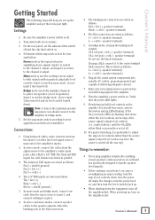
... the channel 1 output, and input 2 is preferable to adjust the amp's level controls rather than the source signal's output level (unless you have the source's control all the sound system components into anything except speakers (unless you have an outboard box specifically designed to handle speakerlevel signals). • Before making connections to remember: jacks, either the binding posts or the NL4 connectors. Input 1 is best for amplifying stereo signals. Using balanced cables, make the changes, turn the power back on the amplifier. speaker...
... the channel 1 output, and input 2 is preferable to adjust the amp's level controls rather than the source signal's output level (unless you have the source's control all the sound system components into anything except speakers (unless you have an outboard box specifically designed to handle speakerlevel signals). • Before making connections to remember: jacks, either the binding posts or the NL4 connectors. Input 1 is best for amplifying stereo signals. Using balanced cables, make the changes, turn the power back on the amplifier. speaker...
Owners Manual
Page 6
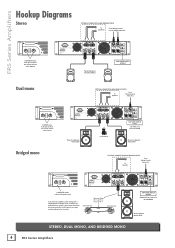
... USER SERVICEABLE PARTS INSIDE. AVIS: N'OUVREZ PAS LA COUVERTURE. OPTIONAL CONNECTION USING BINDING POSTS + To Speaker From Mixing Console Mono Out + CHANNEL 2 BRIDGED CHANNEL 1 SPEAKER OUTPUTS Use only class 3 wiring PIN PIN PIN 1+ 1 BRIDGED 1+ 2+ 1+ 1 PIN CH 2 2+ 2 1+ 1 CH 1 FILTER SUBSONIC @ 30Hz CLIP LIMIT AMP MODE OO In BRIDGED mode, only use this gain control If you have two amplifiers, each could power a single speaker in bridged mono, to the other. Crossover Cable Pin...
... USER SERVICEABLE PARTS INSIDE. AVIS: N'OUVREZ PAS LA COUVERTURE. OPTIONAL CONNECTION USING BINDING POSTS + To Speaker From Mixing Console Mono Out + CHANNEL 2 BRIDGED CHANNEL 1 SPEAKER OUTPUTS Use only class 3 wiring PIN PIN PIN 1+ 1 BRIDGED 1+ 2+ 1+ 1 PIN CH 2 2+ 2 1+ 1 CH 1 FILTER SUBSONIC @ 30Hz CLIP LIMIT AMP MODE OO In BRIDGED mode, only use this gain control If you have two amplifiers, each could power a single speaker in bridged mono, to the other. Crossover Cable Pin...
Owners Manual
Page 7
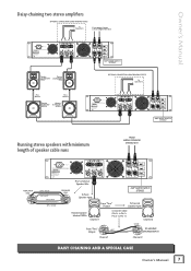
NO USER SERVICEABLE PARTS INSIDE. CHANNEL 2 BRIDGED CHANNEL 1 SPEAKER OUTPUTS Use only class 3 wiring PIN PIN PIN 1+ 1 BRIDGED 1+ 2+ 1+ 1 PIN CH 2 2+ 2 1+ 1 CH 1 Passive Passive Loudspeaker Loudspeaker S512 S512 Pole Mount Pole Mount Passive Passive Subwoofer Subwoofer S518S S518S FILTER SUBSONIC @ 30Hz CLIP LIMIT AMP MODE AMP MODE SWITCH STEREO OPTIONAL CONNECTION USING BINDING POSTS + + To Speakers POWER CONSUMPTION 2000 W THIS DEVICE COMPLIES WITH PART 15 OF THE FCC RULES. CHANNEL 2 BRIDGED CHANNEL 1 SPEAKER OUTPUTS Use only class 3 wiring PIN ...
NO USER SERVICEABLE PARTS INSIDE. CHANNEL 2 BRIDGED CHANNEL 1 SPEAKER OUTPUTS Use only class 3 wiring PIN PIN PIN 1+ 1 BRIDGED 1+ 2+ 1+ 1 PIN CH 2 2+ 2 1+ 1 CH 1 Passive Passive Loudspeaker Loudspeaker S512 S512 Pole Mount Pole Mount Passive Passive Subwoofer Subwoofer S518S S518S FILTER SUBSONIC @ 30Hz CLIP LIMIT AMP MODE AMP MODE SWITCH STEREO OPTIONAL CONNECTION USING BINDING POSTS + + To Speakers POWER CONSUMPTION 2000 W THIS DEVICE COMPLIES WITH PART 15 OF THE FCC RULES. CHANNEL 2 BRIDGED CHANNEL 1 SPEAKER OUTPUTS Use only class 3 wiring PIN ...
Owners Manual
Page 8
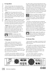
... 4 ohms: FRS•1700 = 540 watts per channel into 4 ohms FRS•2800 = 850 watts per channel into 4 ohms This equates to a gain of line-level sources such as the final adjustment to set all the way down the power transistors. 3. Also, you could use them down the source signal (i.e., the mixer's master faders) or the amplifier's level controls. The amplifier is pressed in . If the level controls are just hitting the full output of the switch...
... 4 ohms: FRS•1700 = 540 watts per channel into 4 ohms FRS•2800 = 850 watts per channel into 4 ohms This equates to a gain of line-level sources such as the final adjustment to set all the way down the power transistors. 3. Also, you could use them down the source signal (i.e., the mixer's master faders) or the amplifier's level controls. The amplifier is pressed in . If the level controls are just hitting the full output of the switch...
Owners Manual
Page 9
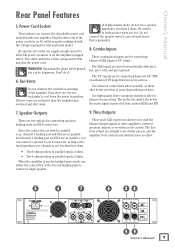
... INTERFERENCE THAT MAY CAUSE UNDESIRED OPERATION. NO USER SERVICEABLE PARTS INSIDE. The XLR inputs are in parallel), you can connect a speaker to each connector, as long as the total impedance per channel is where you to send the balanced input signals to connect a single speaker. 5 6 FRS•2800 FAST RECOVERY POWER AMPLIFIER POWER CONSUMPTION 2000 W THIS DEVICE COMPLIES WITH PART 15 OF THE FCC RULES. Owner's Manual Rear Panel Features 5. NE PAS OUVRIR...
... INTERFERENCE THAT MAY CAUSE UNDESIRED OPERATION. NO USER SERVICEABLE PARTS INSIDE. The XLR inputs are in parallel), you can connect a speaker to each connector, as long as the total impedance per channel is where you to send the balanced input signals to connect a single speaker. 5 6 FRS•2800 FAST RECOVERY POWER AMPLIFIER POWER CONSUMPTION 2000 W THIS DEVICE COMPLIES WITH PART 15 OF THE FCC RULES. Owner's Manual Rear Panel Features 5. NE PAS OUVRIR...
Owners Manual
Page 10
... to adjust the gain (turn the channel 2 level control all times. Square waves sound awful, and could damage a loudspeaker. FRS•2800 FAST RECOVERY POWER AMPLIFIER POWER CONSUMPTION 2000 W THIS DEVICE COMPLIES WITH PART 15 OF THE FCC RULES. Stereo: This is the normal position used in most speakers can reduce low-frequency stage noise (footsteps) and accidental microphone pops that is, neither is independent. It accepts a single input (input...
... to adjust the gain (turn the channel 2 level control all times. Square waves sound awful, and could damage a loudspeaker. FRS•2800 FAST RECOVERY POWER AMPLIFIER POWER CONSUMPTION 2000 W THIS DEVICE COMPLIES WITH PART 15 OF THE FCC RULES. Stereo: This is the normal position used in most speakers can reduce low-frequency stage noise (footsteps) and accidental microphone pops that is, neither is independent. It accepts a single input (input...
Owners Manual
Page 11
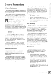
.... However, you must secure the rear support brackets of the amplifier to allow sufficient air space around the front and rear of the rack using well-defined, articulate, wide-range program material. Owner's Manual General Precautions AC Power Requirements The amplifier's power cord should be plugged into it in good operating and cosmetic condition. • Testing: Periodically test the system for all components mounted in a rack that a stiff...
.... However, you must secure the rear support brackets of the amplifier to allow sufficient air space around the front and rear of the rack using well-defined, articulate, wide-range program material. Owner's Manual General Precautions AC Power Requirements The amplifier's power cord should be plugged into it in good operating and cosmetic condition. • Testing: Periodically test the system for all components mounted in a rack that a stiff...

Owners Manual
Page 12
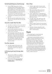
... the front panel illuminated? The signal level is present. • If the speakers are a proper match for the correct connections. For example: input(s) or summing bus in your Mackie product away. If not, make sure the amp mode switch is live . • Are all equipment set to produce sound in the amplifier. • Loudspeakers not working properly. 12 FRS Series Amplifiers No Sound or Low Output • Loudspeaker cables or...
... the front panel illuminated? The signal level is present. • If the speakers are a proper match for the correct connections. For example: input(s) or summing bus in your Mackie product away. If not, make sure the amp mode switch is live . • Are all equipment set to produce sound in the amplifier. • Loudspeakers not working properly. 12 FRS Series Amplifiers No Sound or Low Output • Loudspeaker cables or...
Owners Manual
Page 13
... nearest factory-authorized service center is with your nearest service center, visit www.mackie.com, click "Support" and select "Locate a Service Center." It needs plenty of fresh air to plug all cables and connections for normal operation. Tech Support will tell you can call our Tech Support department at one end of the speaker cable connections. If the other equipment are not a user-serviceable. To locate your speaker cabling or the loudspeakers. Use an...
... nearest factory-authorized service center is with your nearest service center, visit www.mackie.com, click "Support" and select "Locate a Service Center." It needs plenty of fresh air to plug all cables and connections for normal operation. Tech Support will tell you can call our Tech Support department at one end of the speaker cable connections. If the other equipment are not a user-serviceable. To locate your speaker cabling or the loudspeakers. Use an...
Owners Manual
Page 14
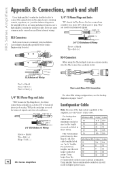
... amplifier. The Min Metric WG 4 ohm 8 ohm cable lengths listed 12 are using the NL4 outputs in stereo or mono modes, wire the NL4 connectors as listed in -between the signal source (mixing console, equalizer, etc.) and the balanced inputs to " lengths. If you need, as shown below: 1- 1+ COLD HOT 1- 2+ 1+ 2- FRS Series Amplifiers Appendix B: Connections, math and stuff Use a high-quality 3-conductor shielded cable to connect the signal between 14 lengths, use...
... amplifier. The Min Metric WG 4 ohm 8 ohm cable lengths listed 12 are using the NL4 outputs in stereo or mono modes, wire the NL4 connectors as listed in -between the signal source (mixing console, equalizer, etc.) and the balanced inputs to " lengths. If you need, as shown below: 1- 1+ COLD HOT 1- 2+ 1+ 2- FRS Series Amplifiers Appendix B: Connections, math and stuff Use a high-quality 3-conductor shielded cable to connect the signal between 14 lengths, use...

Owners Manual
Page 15
... speaker's frequency range. just divide the value by the following sections show will change. For instance, two 4-ohm speakers in parallel, will still work, but nothing that you can't do with series configurations is greater than 0.5 dB power losses are two basic ways of speakers. Owner's Manual 15 If one . • Reduce the low-frequency output by engaging the low cut filter. • Never plug the amplifier outputs...
... speaker's frequency range. just divide the value by the following sections show will change. For instance, two 4-ohm speakers in parallel, will still work, but nothing that you can't do with series configurations is greater than 0.5 dB power losses are two basic ways of speakers. Owner's Manual 15 If one . • Reduce the low-frequency output by engaging the low cut filter. • Never plug the amplifier outputs...
Owners Manual
Page 16
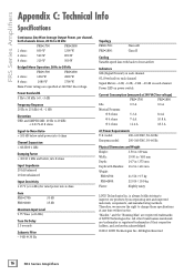
... reserve the right to -front airflow Indicators SIG (Signal Present) on each channel OL (Overload) on each channel Signal Meters -3 dB, -6 dB, -9 dB. -20 dB on each channel Power LED on power switch Current Consumption (measured at 240 VAC line voltage) FRS•1700 FRS•2800 Idle 0.5 A 0.6 A Musical Program: @ 8 ohms 5.3 A 8.4 A @ 4 ohms 7.4 A 10.8 A @ 2 ohms 11.4 A 18.3 A AC Power Requirements U.S. "Mackie," and the "Running Man" are registered trademarks of...
... reserve the right to -front airflow Indicators SIG (Signal Present) on each channel OL (Overload) on each channel Signal Meters -3 dB, -6 dB, -9 dB. -20 dB on each channel Power LED on power switch Current Consumption (measured at 240 VAC line voltage) FRS•1700 FRS•2800 Idle 0.5 A 0.6 A Musical Program: @ 8 ohms 5.3 A 8.4 A @ 4 ohms 7.4 A 10.8 A @ 2 ohms 11.4 A 18.3 A AC Power Requirements U.S. "Mackie," and the "Running Man" are registered trademarks of...
Owners Manual
Page 17
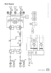
...OFFSET OVER TEMP SHORT CIRCUIT CURRENT LIMIT AMPLIFIER HVDC+ LVDC+ POWER AMP 2 LVDC- HVDC- + - 1+ + 1- 2+ 2- - Owner's Manual Block Diagram HVDC- VDC+ METER DISPLAY FAN FAN VDC- 17 Owner's Manual INPUT 1 BALANCED LINE INPUT (XLR-F) INPUT 1 BALANCED LINE INPUT (TRS) INPUT 2 BALANCED LINE INPUT (XLR-F) INPUT 2 BALANCED LINE INPUT (TRS) POWER SWITCH ON OFF SUBSONIC FILTER ON OFF CHANNEL 1 LEVEL AMP MODE SWITCH CHANNEL 2 MONO LEVEL STEREO BRIDGE SWITCHING POWER SUPPLY 120V/240V JUMPER SWITCHING POWER CONTROLLER AMP MODE SWITCH MONO STEREO BRIDGE ON OFF CLIP LIMITER ON...
...OFFSET OVER TEMP SHORT CIRCUIT CURRENT LIMIT AMPLIFIER HVDC+ LVDC+ POWER AMP 2 LVDC- HVDC- + - 1+ + 1- 2+ 2- - Owner's Manual Block Diagram HVDC- VDC+ METER DISPLAY FAN FAN VDC- 17 Owner's Manual INPUT 1 BALANCED LINE INPUT (XLR-F) INPUT 1 BALANCED LINE INPUT (TRS) INPUT 2 BALANCED LINE INPUT (XLR-F) INPUT 2 BALANCED LINE INPUT (TRS) POWER SWITCH ON OFF SUBSONIC FILTER ON OFF CHANNEL 1 LEVEL AMP MODE SWITCH CHANNEL 2 MONO LEVEL STEREO BRIDGE SWITCHING POWER SUPPLY 120V/240V JUMPER SWITCHING POWER CONTROLLER AMP MODE SWITCH MONO STEREO BRIDGE ON OFF CLIP LIMITER ON...
Owners Manual
Page 18
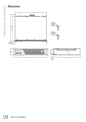
FRS Series Amplifiers Dimensions 17.1 in / 434 mm 14.7 in / 373 mm 13.5 in / 343 mm 1.5 in / 38 mm 3.5 in / 89 mm OO 1 OL -3 -6 -9 -20 MAX SIG 2 OL -3 -6 -9 -20 SIG MAX OO 19.0 in / 483 mm FRS•1700 WEIGHT 21.5 lbs. (9.7 kg) FRS•2800 WEIGHT 22 lbs. (10 kg) 1.5 in / 38 mm 14.7 in / 373 mm 18 FRS Series Amplifiers
FRS Series Amplifiers Dimensions 17.1 in / 434 mm 14.7 in / 373 mm 13.5 in / 343 mm 1.5 in / 38 mm 3.5 in / 89 mm OO 1 OL -3 -6 -9 -20 MAX SIG 2 OL -3 -6 -9 -20 SIG MAX OO 19.0 in / 483 mm FRS•1700 WEIGHT 21.5 lbs. (9.7 kg) FRS•2800 WEIGHT 22 lbs. (10 kg) 1.5 in / 38 mm 14.7 in / 373 mm 18 FRS Series Amplifiers

Owners Manual
Page 19
...thereby. Need help with your amplifier? • Visit www.mackie.com and click Support to the warranty then LOUD or its authorized service representative will at its option, either repair or replace any such nonconforming product, provided that the product will be valid unless set forth in a... Customer gives notice of purchase. For products purchased outside the U.S. Owner's Manual Mackie Limited Warranty Please keep your sales receipt in the United States or Canada through Friday, normal business hours, Pacific Time). For full terms and conditions, as well as evidence of the...
...thereby. Need help with your amplifier? • Visit www.mackie.com and click Support to the warranty then LOUD or its authorized service representative will at its option, either repair or replace any such nonconforming product, provided that the product will be valid unless set forth in a... Customer gives notice of purchase. For products purchased outside the U.S. Owner's Manual Mackie Limited Warranty Please keep your sales receipt in the United States or Canada through Friday, normal business hours, Pacific Time). For full terms and conditions, as well as evidence of the...

Owners Manual
Page 20
16220 Wood-Red Road NE Woodinville, WA 98072 • USA Phone: 425.487.4333 Toll-free: 800.898.3211 Fax: 425.487.4337 www.mackie.com
16220 Wood-Red Road NE Woodinville, WA 98072 • USA Phone: 425.487.4333 Toll-free: 800.898.3211 Fax: 425.487.4337 www.mackie.com


