
Owners Manual
Page 2
... entering a power tool will reduce risk of research and development, the specifications herein are subject to change without notice. • Specifications and battery cartridge may result in a damp location is earthed or grounded. 6. Damaged or entangled cords increase the risk of inattention while operating power tools may differ from heat, oil, sharp edges or moving parts. A moment of electric shock. 8. ENGLISH (Original instructions) SPECIFICATIONS Model LXPH03 Drilling into...
... entering a power tool will reduce risk of research and development, the specifications herein are subject to change without notice. • Specifications and battery cartridge may result in a damp location is earthed or grounded. 6. Damaged or entangled cords increase the risk of inattention while operating power tools may differ from heat, oil, sharp edges or moving parts. A moment of electric shock. 8. ENGLISH (Original instructions) SPECIFICATIONS Model LXPH03 Drilling into...
Owners Manual
Page 3
... give the operator an electric shock. 3 Remove any adjustments, changing accessories, or storing power tools. Use of fire when used . avoid contact. Use auxiliary handle(s), if supplied with your hair, clothing, and gloves away from other metal objects, like paper clips, coins, keys, nails, screws or other battery packs may contact hidden wiring. Keep cutting tools sharp and clean. Carrying power tools with the tool. Battery tool use and care 17. Ensure the switch is not...
... give the operator an electric shock. 3 Remove any adjustments, changing accessories, or storing power tools. Use of fire when used . avoid contact. Use auxiliary handle(s), if supplied with your hair, clothing, and gloves away from other metal objects, like paper clips, coins, keys, nails, screws or other battery packs may contact hidden wiring. Keep cutting tools sharp and clean. Carrying power tools with the tool. Battery tool use and care 17. Ensure the switch is not...

Owners Manual
Page 4
... excessively shorter, stop tool operation and charge the battery cartridge when you notice less tool power. 2. If electrolyte gets into your eyesight. 5. SAVE THESE INSTRUCTIONS. Always be sure you do not use it . 4. Be sure no load speed ・ revolutions or reciprocation per minute ・ number of your eyes, rinse them out with product (gained from rotating parts. 8. Hold the tool firmly. 7. Do...
... excessively shorter, stop tool operation and charge the battery cartridge when you notice less tool power. 2. If electrolyte gets into your eyesight. 5. SAVE THESE INSTRUCTIONS. Always be sure you do not use it . 4. Be sure no load speed ・ revolutions or reciprocation per minute ・ number of your eyes, rinse them out with product (gained from rotating parts. 8. Hold the tool firmly. 7. Do...

Owners Manual
Page 5
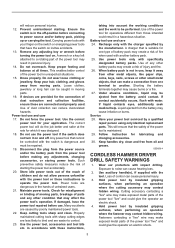
... trigger. 5 Button 1 3. Insert it all the way until the red indicator cannot be sure that the tool is switched off and the battery cartridge is being inserted correctly. In this situation, remove and recharge the battery. If the tool does not start the tool, simply pull the switch trigger. Tool speed is increased by increasing pressure on lighting while the switch trigger is removed before installing or removing of the battery cartridge. Lamp 1 012128 Lithium-ion batteries...
... trigger. 5 Button 1 3. Insert it all the way until the red indicator cannot be sure that the tool is switched off and the battery cartridge is being inserted correctly. In this situation, remove and recharge the battery. If the tool does not start the tool, simply pull the switch trigger. Tool speed is increased by increasing pressure on lighting while the switch trigger is removed before installing or removing of the battery cartridge. Lamp 1 012128 Lithium-ion batteries...
Owners Manual
Page 6
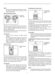
... B side for your work needs by turning the adjusting ring so that the arrow on the tool body points toward the mark on the tool body. Changing the direction of rotation. First, slide the action mode change the direction of rotation before operation. • Use the reversing switch only after the tool comes to a complete stop. NOTE: • The adjusting ring does not lock when the pointer is...
... B side for your work needs by turning the adjusting ring so that the arrow on the tool body points toward the mark on the tool body. Changing the direction of rotation. First, slide the action mode change the direction of rotation before operation. • Use the reversing switch only after the tool comes to a complete stop. NOTE: • The adjusting ring does not lock when the pointer is...
Owners Manual
Page 7
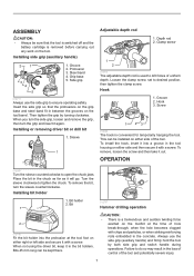
... counterclockwise. Screw 1 23 012698 The hook is used to ensure operating safety. Turn the sleeve clockwise to desired position, then tighten the clamp screw. Bit 1 2 012708 Fit the bit holder into a groove in the tool housing on either side and then secure it with a screw. Loosen the clamp screw, set to tighten the chuck. Hook 1. To remove the bit, turn the grip and insert it out. Always use the side grip to drill holes...
... counterclockwise. Screw 1 23 012698 The hook is used to ensure operating safety. Turn the sleeve clockwise to desired position, then tighten the clamp screw. Bit 1 2 012708 Fit the bit holder into a groove in the tool housing on either side and then secure it with a screw. Loosen the clamp screw, set to tighten the chuck. Hook 1. To remove the bit, turn the grip and insert it out. Always use the side grip to drill holes...

Owners Manual
Page 8
... metal To prevent the bit from slipping when starting a hole, make an indentation with a fresh battery. The guide screw makes drilling easier by setting the reversing switch to reverse rotation in position and prevent it points to the marking. Replacing carbon brushes 1. Both carbon brushes should be aligned in the holders. The adjusting ring can be drilled dry. Screwdriving operation First, slide the action mode change lever so that it from...
... metal To prevent the bit from slipping when starting a hole, make an indentation with a fresh battery. The guide screw makes drilling easier by setting the reversing switch to reverse rotation in position and prevent it points to the marking. Replacing carbon brushes 1. Both carbon brushes should be aligned in the holders. The adjusting ring can be drilled dry. Screwdriving operation First, slide the action mode change lever so that it from...

Owners Manual
Page 9
... like. 1. If you need any assistance for its stated purpose. Rear cover 2. Only use of any other accessories or attachments might present a risk of the housing with your local Makita Service Center. • Drill bits • Hammer drill bits • Screw bits • Blow-out bulb • Safety goggles • Makita genuine battery and charger • Grip assembly • Depth rod • Hook • Rubber pad assembly • Wool bonnet...
... like. 1. If you need any assistance for its stated purpose. Rear cover 2. Only use of any other accessories or attachments might present a risk of the housing with your local Makita Service Center. • Drill bits • Hammer drill bits • Screw bits • Blow-out bulb • Safety goggles • Makita genuine battery and charger • Grip assembly • Depth rod • Hook • Rubber pad assembly • Wool bonnet...

Owners Manual
Page 10
... workmanship or material, Makita will repair (or at our option, replace) without charge. MAKITA LIMITED ONE YEAR WARRANTY Warranty Policy Every Makita tool is caused by others: repairs are required because of normal wear and tear: the tool has been abused, misused or improperly maintained: alterations have other rights which vary from the date of Makita's Factory or Authorized Service Centers. Some...
... workmanship or material, Makita will repair (or at our option, replace) without charge. MAKITA LIMITED ONE YEAR WARRANTY Warranty Policy Every Makita tool is caused by others: repairs are required because of normal wear and tear: the tool has been abused, misused or improperly maintained: alterations have other rights which vary from the date of Makita's Factory or Authorized Service Centers. Some...

Parts Breakdown
Page 2
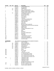
... C30 346566-9 GRIP SPRING 60 A01 C40 453584-1 GRIP BASE 60 A01 C50 265785-7 THUMB SCREW M5X10 A01 C60 931202-6 HEX. FLAT HEAD SCREW M6X22 A 12 766015-4 KEYLESS DRILL CHUCK 13 13 265995-6 TAPPING SCREW 4X18 14 126099-8 GEAR ASSEMBLY 15 638989-8 YOKE UNIT 16 619301-1 ARMATURE 17 638614-1 BRUSH HOLDER COMPLETE 18 CB440 CARBON BRUSH CB-440 (195021-6) 19 263032-0 RUBBER PIN 4 20 453394...
... C30 346566-9 GRIP SPRING 60 A01 C40 453584-1 GRIP BASE 60 A01 C50 265785-7 THUMB SCREW M5X10 A01 C60 931202-6 HEX. FLAT HEAD SCREW M6X22 A 12 766015-4 KEYLESS DRILL CHUCK 13 13 265995-6 TAPPING SCREW 4X18 14 126099-8 GEAR ASSEMBLY 15 638989-8 YOKE UNIT 16 619301-1 ARMATURE 17 638614-1 BRUSH HOLDER COMPLETE 18 CB440 CARBON BRUSH CB-440 (195021-6) 19 263032-0 RUBBER PIN 4 20 453394...

Parts Breakdown
Page 3
A10 C10 419216-0 A10 C20 417724-5 A10 C30 419268-1 A10 C40 419269-9 A10 C50 324667-3 E01 810300-8 D01 652045-0 HANDLE LATCH PLASTIC CASE LID PLATE SHAFT CAUTION LABEL +PAN HEAD SCREW M3.5X5 1 PC. 2 PC. 1 PC. 5 PC. 1 PC. 1 PC. 2 PC.
A10 C10 419216-0 A10 C20 417724-5 A10 C30 419268-1 A10 C40 419269-9 A10 C50 324667-3 E01 810300-8 D01 652045-0 HANDLE LATCH PLASTIC CASE LID PLATE SHAFT CAUTION LABEL +PAN HEAD SCREW M3.5X5 1 PC. 2 PC. 1 PC. 5 PC. 1 PC. 1 PC. 2 PC.
Parts Diagram
Page 1
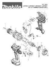
03 - 2012 LXPH03 / LXPH03Z / LXPH03Z1 / LXPH031 18V 1/2" HAMMER DRIVER DRILL 1 2 4 11 A07 13 5 8 6 7 14 15 16 2 27 26 25 24 23 22 3 10 17 18 20 19 21
03 - 2012 LXPH03 / LXPH03Z / LXPH03Z1 / LXPH031 18V 1/2" HAMMER DRIVER DRILL 1 2 4 11 A07 13 5 8 6 7 14 15 16 2 27 26 25 24 23 22 3 10 17 18 20 19 21
Parts Diagram
Page 2
... SCREW 4X18 GEAR ASSEMBLY YOKE UNIT ARMATURE BRUSH HOLDER COMPLETE CARBON BRUSH CB-440 2PC/SET W/ORIGIN RUBBER PIN 4 REAR COVER TAPPING SCREW BIND PT 3X16 TERMINAL SEAL SPONGE A PAN HEAD SCREW M3X10 SPONGE B HEAT SINK + SCREW M4X12 (F/HOOK) CARTON FOR LXPH03Z +PAN HEAD SCREW M3.5X5 CAUTION LABEL ACCESSORIS - NUT M5 A03 346449-3 HOOK A04 452947-8 BIT HOLDER A05 784637-8 +- BIT 2-45 A06 122576-8 STOPPER POLE ASS'Y A07 766015-4 1/2" KEYLESS DRILL CHUCK...
... SCREW 4X18 GEAR ASSEMBLY YOKE UNIT ARMATURE BRUSH HOLDER COMPLETE CARBON BRUSH CB-440 2PC/SET W/ORIGIN RUBBER PIN 4 REAR COVER TAPPING SCREW BIND PT 3X16 TERMINAL SEAL SPONGE A PAN HEAD SCREW M3X10 SPONGE B HEAT SINK + SCREW M4X12 (F/HOOK) CARTON FOR LXPH03Z +PAN HEAD SCREW M3.5X5 CAUTION LABEL ACCESSORIS - NUT M5 A03 346449-3 HOOK A04 452947-8 BIT HOLDER A05 784637-8 +- BIT 2-45 A06 122576-8 STOPPER POLE ASS'Y A07 766015-4 1/2" KEYLESS DRILL CHUCK...


