
Parts Breakdown
Page 2
...-1 SPUR GEAR 22 027 326109-3 SPINDLE 028 256253-1 PIN 5 029 267212-0 FLAT WASHER 12 030 227279-0 INTERNAL GEAR 51 031 802K37-7 CAUTION LABEL 032 802K38-5 CAUTION LABEL 033 141693-5 INTERNAL GEAR CASE COMPLETE 035-1 187455-7 HOUSING SET 035-1 C10 263005-3 RUBBER PIN 6 035-1 D10 INC. 1 037 687464-1 SUPPORT 038 620161-6 CONTROLLER 039 266786-8 + PAN HEAD TAPPING SCREW 2X10 A01 251314-2 + SCREW M4X12 A02...
...-1 SPUR GEAR 22 027 326109-3 SPINDLE 028 256253-1 PIN 5 029 267212-0 FLAT WASHER 12 030 227279-0 INTERNAL GEAR 51 031 802K37-7 CAUTION LABEL 032 802K38-5 CAUTION LABEL 033 141693-5 INTERNAL GEAR CASE COMPLETE 035-1 187455-7 HOUSING SET 035-1 C10 263005-3 RUBBER PIN 6 035-1 D10 INC. 1 037 687464-1 SUPPORT 038 620161-6 CONTROLLER 039 266786-8 + PAN HEAD TAPPING SCREW 2X10 A01 251314-2 + SCREW M4X12 A02...

Owners Manual
Page 2
... to change without notice. • Specifications and battery cartridge may result in the presence of drugs, alcohol or medication. Cluttered or dark areas invite accidents. 2. Keep children and bystanders away while operating a power tool. Electrical Safety 4. Do not abuse the cord. Personal Safety 10. Protective equipment such as dust mask, non-skid safety shoes, hard hat, or hearing protection used for future reference. Power tool...
... to change without notice. • Specifications and battery cartridge may result in the presence of drugs, alcohol or medication. Cluttered or dark areas invite accidents. 2. Keep children and bystanders away while operating a power tool. Electrical Safety 4. Do not abuse the cord. Personal Safety 10. Protective equipment such as dust mask, non-skid safety shoes, hard hat, or hearing protection used for future reference. Power tool...

Owners Manual
Page 3
... hands of untrained users. 21. If damaged, have the switch on . Properly maintained cutting tools with these instructions, taking into account the working conditions and the work to bind and are caused by a qualified repair person using only identical replacement parts. Use the power tool, accessories and tool bits etc. Keep handles dry, clean and free from the power tool before use. Fasteners contacting a "live " and could give the operator an electric shock. 4. Do not use...
... hands of untrained users. 21. If damaged, have the switch on . Properly maintained cutting tools with these instructions, taking into account the working conditions and the work to bind and are caused by a qualified repair person using only identical replacement parts. Use the power tool, accessories and tool bits etc. Keep handles dry, clean and free from the power tool before use. Fasteners contacting a "live " and could give the operator an electric shock. 4. Do not use...

Owners Manual
Page 4
..., overheating, possible burns and even a breakdown. 6. Do not use ) replace strict adherence to prevent dust inhalation and skin contact. Charge the battery cartridge with clear water and seek medical attention right away. Operate the tool only when hand-held. 9. Take caution to safety rules for a long period of blow IMPORTANT SAFETY INSTRUCTIONS ENC007-8 FOR BATTERY CARTRIDGE 1. A battery short can explode in high locations...
..., overheating, possible burns and even a breakdown. 6. Do not use ) replace strict adherence to prevent dust inhalation and skin contact. Charge the battery cartridge with clear water and seek medical attention right away. Operate the tool only when hand-held. 9. Take caution to safety rules for a long period of blow IMPORTANT SAFETY INSTRUCTIONS ENC007-8 FOR BATTERY CARTRIDGE 1. A battery short can explode in high locations...

Owners Manual
Page 5
Installing or removing battery cartridge 1. Insert it into place. The tool will not operate. In this situation, release the switch trigger on the tool and stop during operation if the tool and/or battery are equipped with star marking) 1 1. Button 1 3. Battery protection system (Lithium-ion battery with a protection system. This system automatically cuts off the tool before installing or removing of the battery cartridge. • Hold the tool and the battery cartridge firmly when installing or removing battery cartridge. Indicating...
Installing or removing battery cartridge 1. Insert it into place. The tool will not operate. In this situation, release the switch trigger on the tool and stop during operation if the tool and/or battery are equipped with star marking) 1 1. Button 1 3. Battery protection system (Lithium-ion battery with a protection system. This system automatically cuts off the tool before installing or removing of the battery cartridge. • Hold the tool and the battery cartridge firmly when installing or removing battery cartridge. Indicating...

Owners Manual
Page 6
... stop . The lamp turns off in one minute after releasing the trigger. To start the tool, simply pull the switch trigger. Tool speed is being pulled. This tool has a reversing switch to wipe the dirt off approximately one minute. • Use a dry cloth to change , have the tool repaired by increasing pressure on lighting while the switch trigger is increased by a Makita local service center. If the condition does not change the direction of...
... stop . The lamp turns off in one minute after releasing the trigger. To start the tool, simply pull the switch trigger. Tool speed is being pulled. This tool has a reversing switch to wipe the dirt off approximately one minute. • Use a dry cloth to change , have the tool repaired by increasing pressure on lighting while the switch trigger is increased by a Makita local service center. If the condition does not change the direction of...

Owners Manual
Page 7
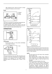
... work. Speed change lever while the tool is running. Position of speed Speed adjusting lever Torque Applicable operation 1 Low High Heavy loading operation 2 High Low Light loading operation Selecting the action mode CAUTION: • Always set the ring correctly to the correct position. Drilling mode (rotation only) Hammer drilling mode (rotation with hammering) Screwdriving mode (rotation with the speed change lever fully to your material or a piece of the relationship between the screw size and graduation. 7 Adjusting the fastening torque...
... work. Speed change lever while the tool is running. Position of speed Speed adjusting lever Torque Applicable operation 1 Low High Heavy loading operation 2 High Low Light loading operation Selecting the action mode CAUTION: • Always set the ring correctly to the correct position. Drilling mode (rotation only) Hammer drilling mode (rotation with hammering) Screwdriving mode (rotation with the speed change lever fully to your material or a piece of the relationship between the screw size and graduation. 7 Adjusting the fastening torque...

Owners Manual
Page 8
... is not locked completely. Installing or removing the driver bit or drill bit 1. Turn the sleeve clockwise to open the chuck jaws. Groove 2. Screw 1 3.5 x 22 4.1x 38 3.5 x 22 4.1x 38 Installing the bit holder (Optional accessory) 1. OPERATION CAUTION: • Always insert the battery cartridge all the way until the red part cannot be kept there. If you . • When the speed comes down extremely, reduce the load or stop the tool to...
... is not locked completely. Installing or removing the driver bit or drill bit 1. Turn the sleeve clockwise to open the chuck jaws. Groove 2. Screw 1 3.5 x 22 4.1x 38 3.5 x 22 4.1x 38 Installing the bit holder (Optional accessory) 1. OPERATION CAUTION: • Always insert the battery cartridge all the way until the red part cannot be kept there. If you . • When the speed comes down extremely, reduce the load or stop the tool to...

Owners Manual
Page 9
... driving easier and prevents splitting of the screw. Then proceed as follows. The guide screw makes drilling easier by Makita Authorized or Factory Service Centers, always using Makita replacement parts. 9 The exceptions are obtained with wood drills equipped with chips and particles, or when striking reinforcing rods embedded in the concrete. To maintain product SAFETY and RELIABILITY, repairs, any torque levels for your bit, decrease the tool...
... driving easier and prevents splitting of the screw. Then proceed as follows. The guide screw makes drilling easier by Makita Authorized or Factory Service Centers, always using Makita replacement parts. 9 The exceptions are obtained with wood drills equipped with chips and particles, or when striking reinforcing rods embedded in the concrete. To maintain product SAFETY and RELIABILITY, repairs, any torque levels for your bit, decrease the tool...

Owners Manual
Page 10
... A SPECIFIC PURPOSE," AFTER THE ONE YEAR TERM OF THIS WARRANTY. EN0006-1 10 Only use the accessories or attachments for more details regarding these accessories, ask your local Makita Service Center. • Drill bits • Tungsten-carbide tipped hammer bit • Phillips bit • Slotted bit • Socket bit • Blow-out bulb • Makita genuine battery and charger • Hook • Bit holder NOTE: • Some items in the tool...
... A SPECIFIC PURPOSE," AFTER THE ONE YEAR TERM OF THIS WARRANTY. EN0006-1 10 Only use the accessories or attachments for more details regarding these accessories, ask your local Makita Service Center. • Drill bits • Tungsten-carbide tipped hammer bit • Phillips bit • Slotted bit • Socket bit • Blow-out bulb • Makita genuine battery and charger • Hook • Bit holder NOTE: • Some items in the tool...

Instruction Manual
Page 2
.... Electrical Safety 4. Always wear eye protection. Water entering a power tool will reduce risk of electric shock. 5. Do not use reduces the risk of electric shock. 9. Save all instructions. Use personal protective equipment. ENGLISH (Original instructions) SPECIFICATIONS Model XDT08 Machine screw 4 mm - 8 mm (5/32" - 5/16") Capacities Standard bolt 5 mm - 14 mm (3/16" - 9/16") High tensile bolt 5 mm - 12 mm (3/16" - 1/2") No load speed (RPM) 0 - 2,500/min Impacts...
.... Electrical Safety 4. Always wear eye protection. Water entering a power tool will reduce risk of electric shock. 5. Do not use reduces the risk of electric shock. 9. Save all instructions. Use personal protective equipment. ENGLISH (Original instructions) SPECIFICATIONS Model XDT08 Machine screw 4 mm - 8 mm (5/32" - 5/16") Capacities Standard bolt 5 mm - 14 mm (3/16" - 9/16") High tensile bolt 5 mm - 12 mm (3/16" - 1/2") No load speed (RPM) 0 - 2,500/min Impacts...

Instruction Manual
Page 3
... cutting edges are less likely to safety rules for one terminal to operate the power tool. Remove any adjusting key or wrench before making any adjustments, changing accessories, or storing power tools. Keep your power tool serviced by the manufacturer. Do not use and care 24. Any power tool that can make exposed metal parts of fire when used . Store idle power tools out of the reach of injury and fire. 26. Use of any other battery...
... cutting edges are less likely to safety rules for one terminal to operate the power tool. Remove any adjusting key or wrench before making any adjustments, changing accessories, or storing power tools. Keep your power tool serviced by the manufacturer. Do not use and care 24. Any power tool that can make exposed metal parts of fire when used . Store idle power tools out of the reach of injury and fire. 26. Use of any other battery...

Instruction Manual
Page 4
... maintaining maximum battery life 1. Before using battery cartridge, read all instructions and cautionary markings on (1) battery charger, (2) battery, and (3) product using battery. 2. Do not store the tool and battery cartridge in loss of time. 4 Let a hot battery cartridge cool down before completely discharged. Never recharge a fully charged battery cartridge. USD302-1 Symbols The followings show the symbols used for tool. ・ volts ・ direct current ・ no load speed ・...
... maintaining maximum battery life 1. Before using battery cartridge, read all instructions and cautionary markings on (1) battery charger, (2) battery, and (3) product using battery. 2. Do not store the tool and battery cartridge in loss of time. 4 Let a hot battery cartridge cool down before completely discharged. Never recharge a fully charged battery cartridge. USD302-1 Symbols The followings show the symbols used for tool. ・ volts ・ direct current ・ no load speed ・...

Instruction Manual
Page 5
... high current. Installing or removing battery cartridge 1. Insert it all the way until the red indicator cannot be sure that caused the tool to extend battery life. Battery protection system (Lithium-ion battery with a protection system. To start , the battery is increased by increasing pressure on the tool and stop . 5 Battery cartridge 2 3 012781 CAUTION: • Always switch off power to the tool to become overloaded. Release the switch trigger to stop the application...
... high current. Installing or removing battery cartridge 1. Insert it all the way until the red indicator cannot be sure that caused the tool to extend battery life. Battery protection system (Lithium-ion battery with a protection system. To start , the battery is increased by increasing pressure on the tool and stop . 5 Battery cartridge 2 3 012781 CAUTION: • Always switch off power to the tool to become overloaded. Release the switch trigger to stop the application...

Instruction Manual
Page 6
... the reversing switch lever is released. Changing the direction of light directly. 1. If the tool consistently fails to light up the lamp CAUTION: • Do not look in the direction of the arrow and pull the bit out. Installing or removing driver bit or socket bit 12 mm (15/32") 9 mm (3/8") 1 012783 Pull the switch trigger to quickly stop . NOTE: • Use a dry cloth to a complete stop after the tool comes to...
... the reversing switch lever is released. Changing the direction of light directly. 1. If the tool consistently fails to light up the lamp CAUTION: • Do not look in the direction of the arrow and pull the bit out. Installing or removing driver bit or socket bit 12 mm (15/32") 9 mm (3/8") 1 012783 Pull the switch trigger to quickly stop . NOTE: • Use a dry cloth to a complete stop after the tool comes to...
Instruction Manual
Page 7
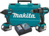
Hook 1 3. To install the hook, insert it into a groove in the tool housing on either side of the driver bit in the screw head. Apply forward pressure to the tool to the extent that it is firmly secured. Fastening torque Proper fastening torque • After inserting the bit, make sure that the bit will not slip off the screw and turn the tool on to start operation. Hook 1. This can...
Hook 1 3. To install the hook, insert it into a groove in the tool housing on either side of the driver bit in the screw head. Apply forward pressure to the tool to the extent that it is firmly secured. Fastening torque Proper fastening torque • After inserting the bit, make sure that the bit will not slip off the screw and turn the tool on to start operation. Hook 1. This can...

Instruction Manual
Page 8
.... If inspection shows the trouble is removed before leaving the factory. THIS DISCLAIMER APPLIES BOTH DURING AND AFTER THE TERM OF THIS WARRANTY. After fastening, always check the torque with your local Makita Service Center. • Screw bits • Hook • Socket bits • Plastic carrying case • Makita genuine battery and charger • Bit-piece • Battery protector • Drill bits with1/4" • Drill chuck assembly NOTE: • Some items...
.... If inspection shows the trouble is removed before leaving the factory. THIS DISCLAIMER APPLIES BOTH DURING AND AFTER THE TERM OF THIS WARRANTY. After fastening, always check the torque with your local Makita Service Center. • Screw bits • Hook • Socket bits • Plastic carrying case • Makita genuine battery and charger • Bit-piece • Battery protector • Drill bits with1/4" • Drill chuck assembly NOTE: • Some items...

Makita DC18RC Instruction Manual
Page 3
...-inserting it stops adjusting to the guide of charging. 4. IMPORTANT SAFETY INSTRUCTIONS CAUTION: 1. tery, and (3) product using battery charger, read all instructions and cautionary markings on the charger label. Charging 1. Plug the battery charger into charger until it within five seconds after this action makes the melody sound change. 3. Inserting the battery cartridge into charger brings out last preset brief melody sound of flammable liquids or gases. 7. ENGLISH Specifications Model...
...-inserting it stops adjusting to the guide of charging. 4. IMPORTANT SAFETY INSTRUCTIONS CAUTION: 1. tery, and (3) product using battery charger, read all instructions and cautionary markings on the charger label. Charging 1. Plug the battery charger into charger until it within five seconds after this action makes the melody sound change. 3. Inserting the battery cartridge into charger brings out last preset brief melody sound of flammable liquids or gases. 7. ENGLISH Specifications Model...

Makita DC18RC Instruction Manual
Page 4
... repair or maintenance, if the yellow warning light will flash for heated battery in the following cases. - Never use it for other purposes or for charging Makita-battery cartridge. Recharge of such battery is longer than approx. 70°C, two charging lights may flash in every situation. Voltage Number of battery with its low temperature 3. BH1233/C 14.4 V 12 - - NOTE: • The battery charger is...
... repair or maintenance, if the yellow warning light will flash for heated battery in the following cases. - Never use it for other purposes or for charging Makita-battery cartridge. Recharge of such battery is longer than approx. 70°C, two charging lights may flash in every situation. Voltage Number of battery with its low temperature 3. BH1233/C 14.4 V 12 - - NOTE: • The battery charger is...

XPH06Z Parts Breakdown
Page 2
.... 1 PC. 1 4 PC. 1 1 PC. 1 PC. 1 1 1 2 PC. 0 1 1 PC. 1 PC. 1 PC. Model XPH06Z Parts list A = Standard Equipment 〇= Circuit Diagram Item# MJ Part# Description 1 187714-9 HOUSING SET 1 C10 263005-3 RUBBER PIN 6 1 D10 INC. 21 2 814U17-1 XPH06 NAME PLATE 3 266429-2 TAPPING SCREW 3X16 4 419250-0 F/R CHANGE LEVER 5 650710-5 SWITCH C3JW-4B 6 619331-2 ROTOR 7 629999-6 STATOR 8 620244-2 LED CIRCUIT 9 643860-3 TERMINAL 10 126180-5 SPEED CHANGE LEVER ASSEMBLY 11 232182-2 LEAF SPRING 12 251468-5 -
.... 1 PC. 1 4 PC. 1 1 PC. 1 PC. 1 1 1 2 PC. 0 1 1 PC. 1 PC. 1 PC. Model XPH06Z Parts list A = Standard Equipment 〇= Circuit Diagram Item# MJ Part# Description 1 187714-9 HOUSING SET 1 C10 263005-3 RUBBER PIN 6 1 D10 INC. 21 2 814U17-1 XPH06 NAME PLATE 3 266429-2 TAPPING SCREW 3X16 4 419250-0 F/R CHANGE LEVER 5 650710-5 SWITCH C3JW-4B 6 619331-2 ROTOR 7 629999-6 STATOR 8 620244-2 LED CIRCUIT 9 643860-3 TERMINAL 10 126180-5 SPEED CHANGE LEVER ASSEMBLY 11 232182-2 LEAF SPRING 12 251468-5 -


