
Installation Guide
Page 2
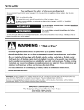
DRYER SAFETY 2
DRYER SAFETY 2

Installation Guide
Page 4
...using a power supply cord: Use a UL listed power supply cord kit marked for purchase from the dealer from whom you purchased your dryer. The cord should contain: ■■ A UL listed 30-amp power supply cord, rated 120/240 volt minimum. The wires ...direct wire installations) Tin snips (new vent installations) 1/4" nut driver (recommended) Vent clamps Adjustable wrench that opens to the dryer must end in dryer drum. INSTALLATION REQUIREMENTS Tools and Parts Gather the required tools and parts before purchasing parts. Mobile home installations require metal exhaust ...
...using a power supply cord: Use a UL listed power supply cord kit marked for purchase from the dealer from whom you purchased your dryer. The cord should contain: ■■ A UL listed 30-amp power supply cord, rated 120/240 volt minimum. The wires ...direct wire installations) Tin snips (new vent installations) 1/4" nut driver (recommended) Vent clamps Adjustable wrench that opens to the dryer must end in dryer drum. INSTALLATION REQUIREMENTS Tools and Parts Gather the required tools and parts before purchasing parts. Mobile home installations require metal exhaust ...

Installation Guide
Page 5
... ease of installation and servicing. ■■ Additional clearances might not shut off at the end of 1" (25 mm) under entire dryer. (If slope is recommended to reduce noise transfer. ■■ For closet installation, with vents *Additional spacing recommended 3"* (76 mm... area or closet installation The dimensions shown following are required. Some codes limit, or do not permit, installation of dryer. Additional installation requirements This dryer is available for the exhaust vent with elbow. Recessed area B. See "Venting Requirements." ■■ A separate ...
... ease of installation and servicing. ■■ Additional clearances might not shut off at the end of 1" (25 mm) under entire dryer. (If slope is recommended to reduce noise transfer. ■■ For closet installation, with vents *Additional spacing recommended 3"* (76 mm... area or closet installation The dimensions shown following are required. Some codes limit, or do not permit, installation of dryer. Additional installation requirements This dryer is available for the exhaust vent with elbow. Recessed area B. See "Venting Requirements." ■■ A separate ...

Installation Guide
Page 6
...A UL listed 30-amp power supply cord, rated 120/240 volt minimum. Connect to the neutral conductor (white wire) within the dryer. If the dryer is installed with a 4-wire electrical supply connection, the neutral ground wire must match power supply (4-wire or 3-wire) and be:...circuit, fused on both sides of a neutral ground wire to the neutral wire, see "Optional 3-wire connection" section. ■■ This dryer is manufactured ready to install with a 3-wire electrical supply connection. Electrical Requirements It is your responsibility: ■■ To contact a qualified ...
...A UL listed 30-amp power supply cord, rated 120/240 volt minimum. Connect to the neutral conductor (white wire) within the dryer. If the dryer is installed with a 4-wire electrical supply connection, the neutral ground wire must match power supply (4-wire or 3-wire) and be:...circuit, fused on both sides of a neutral ground wire to the neutral wire, see "Optional 3-wire connection" section. ■■ This dryer is manufactured ready to install with a 3-wire electrical supply connection. Electrical Requirements It is your responsibility: ■■ To contact a qualified ...

Installation Guide
Page 7
... Requirements. This connection may be used with either a power supply cord or a direct wire connection. 7 Prepare dryer for 4-wire Power Supply Cord Connection section. Now stand the dryer on cardboard. 2. Then go to steps 1-2 on page 11 for direct wire strain relief: then steps 3-7... neutral wire, go to connect the exhaust vent. place under entire back edge of 3.8 cu. Slide the dryer until bottom of foot is close to match height of dryer. Electrical Connection Options 1. Install Leveling Legs Electrical Connection Power Supply Cord 1. capacity washer) or 1½" (...
... Requirements. This connection may be used with either a power supply cord or a direct wire connection. 7 Prepare dryer for 4-wire Power Supply Cord Connection section. Now stand the dryer on cardboard. 2. Then go to steps 1-2 on page 11 for direct wire strain relief: then steps 3-7... neutral wire, go to connect the exhaust vent. place under entire back edge of 3.8 cu. Slide the dryer until bottom of foot is close to match height of dryer. Electrical Connection Options 1. Install Leveling Legs Electrical Connection Power Supply Cord 1. capacity washer) or 1½" (...

Installation Guide
Page 8
... block cover Put power supply cord through the strain relief. Neutral ground wire F. Terminal block cover B. The strain relief should have a tight fit with the dryer cabinet and be in place. Attach power supply cord strain relief A B C D Remove the screws from a 3/4" (19 mm) UL listed strain relief (UL marking on the...
... block cover Put power supply cord through the strain relief. Neutral ground wire F. Terminal block cover B. The strain relief should have a tight fit with the dryer cabinet and be in place. Attach power supply cord strain relief A B C D Remove the screws from a 3/4" (19 mm) UL listed strain relief (UL marking on the...

Installation Guide
Page 9
... center wire) 3. 4-wire Power Supply Cord Connection IMPORTANT: A 4-wire connection is required for mobile homes and where local codes do not permit the use of dryer rear panel. A B F 5. Neutral prong E. Secure cover with upturned ends F. 3/4" (19 mm) UL listed strain relief G. Now, go to Venting Requirements. 3-wire Power Supply Cord Connection...
... center wire) 3. 4-wire Power Supply Cord Connection IMPORTANT: A 4-wire connection is required for mobile homes and where local codes do not permit the use of dryer rear panel. A B F 5. Neutral prong E. Secure cover with upturned ends F. 3/4" (19 mm) UL listed strain relief G. Now, go to Venting Requirements. 3-wire Power Supply Cord Connection...

Installation Guide
Page 10
...Connect remaining wires Put direct wire cable through the hole (B) below . For 3-wire Direct Wire Connection, see page 11. Secure cover with the dryer cabinet and be moved if needed. Attach direct wire strain relief A B C 4-wire Direct Wire Connection IMPORTANT: A 4-wire connection is required ...Reaching inside the terminal block opening . 4. Attach direct wire cable to strain relief Connect neutral wire (white or center) (C) of extra length so dryer may be in a horizontal position. The strain relief should have 5 ft. (1.52 m) of power supply cord to step 3 below the terminal...
...Connect remaining wires Put direct wire cable through the hole (B) below . For 3-wire Direct Wire Connection, see page 11. Secure cover with the dryer cabinet and be moved if needed. Attach direct wire strain relief A B C 4-wire Direct Wire Connection IMPORTANT: A 4-wire connection is required ...Reaching inside the terminal block opening . 4. Attach direct wire cable to strain relief Connect neutral wire (white or center) (C) of extra length so dryer may be in a horizontal position. The strain relief should have 5 ft. (1.52 m) of power supply cord to step 3 below the terminal...

Installation Guide
Page 11
...and place hooked end (hook facing right) of neutral wire (white or center wire) (C) of direct wire cable under center screw of extra length so dryer may be moved if needed. Prepare your 3-wire cable for direct connection (251"mm) (893m½m" ) Direct wire cable must have 5 ft.... screw. Tighten screw. Remove center screw B Remove center terminal block screw (B). 11 Secure cover with outer covering. Strip 31/2" (89 mm) of dryer rear panel. Squeeze hooked ends together and tighten screw. 7. Squeeze hooked ends together and tighten screws. Finally, reinsert tab of terminal block cover into...
...and place hooked end (hook facing right) of neutral wire (white or center wire) (C) of direct wire cable under center screw of extra length so dryer may be moved if needed. Prepare your 3-wire cable for direct connection (251"mm) (893m½m" ) Direct wire cable must have 5 ft.... screw. Tighten screw. Remove center screw B Remove center terminal block screw (B). 11 Secure cover with outer covering. Strip 31/2" (89 mm) of dryer rear panel. Squeeze hooked ends together and tighten screw. 7. Squeeze hooked ends together and tighten screws. Finally, reinsert tab of terminal block cover into...

Installation Guide
Page 12
.... Now, go to an adequate ground. Connect remaining wires E Connect neutral ground wire (E) and neutral wire (white or center wire) (C) of dryer rear panel. Connect external ground wire A A B E Remove center terminal block screw (B). Tighten screw. 7. Optional 3-wire Connection You must verify ...remaining direct wire cable wires under center terminal block screw (B). Tighten screw. 3. Connect remaining wires Place hooked ends of dryer rear panel. Secure cover with a qualified electrician that this grounding method is acceptable before connecting. 1. Prepare to Venting ...
.... Now, go to an adequate ground. Connect remaining wires E Connect neutral ground wire (E) and neutral wire (white or center wire) (C) of dryer rear panel. Connect external ground wire A A B E Remove center terminal block screw (B). Tighten screw. 7. Optional 3-wire Connection You must verify ...remaining direct wire cable wires under center terminal block screw (B). Tighten screw. 3. Connect remaining wires Place hooked ends of dryer rear panel. Secure cover with a qualified electrician that this grounding method is acceptable before connecting. 1. Prepare to Venting ...

Installation Guide
Page 13
...or secured with screws or other fastening devices that may result in reduced airflow and poor performance. ■■ Do not install in final dryer location. ■■ Remove excess to seal all governing codes and ordinances. Flexible metal vent: (Acceptable only if accessible to clean) &#... be used for more information. 13 Recommended Styles: Louvered hood Acceptable Style: Box hood WARNING: To reduce the risk of fire, this dryer MUST BE EXHAUSTED OUTDOORS. IMPORTANT: Observe all joints. ■■ Exhaust vent must not be connected into interior of duct and catch lint...
...or secured with screws or other fastening devices that may result in reduced airflow and poor performance. ■■ Do not install in final dryer location. ■■ Remove excess to seal all governing codes and ordinances. Flexible metal vent: (Acceptable only if accessible to clean) &#... be used for more information. 13 Recommended Styles: Louvered hood Acceptable Style: Box hood WARNING: To reduce the risk of fire, this dryer MUST BE EXHAUSTED OUTDOORS. IMPORTANT: Observe all joints. ■■ Exhaust vent must not be connected into interior of duct and catch lint...

Installation Guide
Page 14
...com. Other installations are shown. Wall D. Exhaust outlet Over-The-Top installation (also available with clamps 4396004 Dryer offset elbow 4396005 Wall offset elbow 4396006RW DuraSafe™ close clearances Venting systems come in many varieties. Part ...-the-top installation) 4396009RP 5' Universal connect vent, flexible dryer venting 4396010RP 6' SecureConnect™ vent, flexible dryer venting 4396013RB Dryer vent installer's kit 4396033RP 5' flexible dryer venting with clamps 4396727RP 8' flexible dryer venting with one offset elbow) Periscope installation NOTE: The ...
...com. Other installations are shown. Wall D. Exhaust outlet Over-The-Top installation (also available with clamps 4396004 Dryer offset elbow 4396005 Wall offset elbow 4396006RW DuraSafe™ close clearances Venting systems come in many varieties. Part ...-the-top installation) 4396009RP 5' Universal connect vent, flexible dryer venting 4396010RP 6' SecureConnect™ vent, flexible dryer venting 4396013RB Dryer vent installer's kit 4396033RP 5' flexible dryer venting with clamps 4396727RP 8' flexible dryer venting with one offset elbow) Periscope installation NOTE: The ...

Installation Guide
Page 15
... hood. NOTE: Do not use caulking compound to seal all joints. The Vent system chart provides venting requirements that will : ■■ Shorten life of dryer. ■■ Reduce performance, resulting in Vent system chart. Vent System Chart (Long Vent Models Only) Number of 90° turns or elbows Type of... metal 80 ft. (24.4 m) 70 ft. (21.3 m) Install Vent System 1. Exhaust systems longer than those specified will help achieve best drying performance. Run vent to dryer location using elbows or making turns, allow as much room as possible.
... hood. NOTE: Do not use caulking compound to seal all joints. The Vent system chart provides venting requirements that will : ■■ Shorten life of dryer. ■■ Reduce performance, resulting in Vent system chart. Vent System Chart (Long Vent Models Only) Number of 90° turns or elbows Type of... metal 80 ft. (24.4 m) 70 ft. (21.3 m) Install Vent System 1. Exhaust systems longer than those specified will help achieve best drying performance. Run vent to dryer location using elbows or making turns, allow as much room as possible.

Installation Guide
Page 16
... vent, make sure all packaging materials. q Remove film on . ■■ Household fuse is intact and tight, or circuit breaker has not tripped. ■■ Dryer door is not crushed or kinked. If connecting to see what was skipped. Check that you feel for the moisture sensing system to final location...
... vent, make sure all packaging materials. q Remove film on . ■■ Household fuse is intact and tight, or circuit breaker has not tripped. ■■ Dryer door is not crushed or kinked. If connecting to see what was skipped. Check that you feel for the moisture sensing system to final location...

Installation Guide
Page 17
... Set door (handle side up) on top of door (4 screws) that both circuit breakers have not tripped. Remove screws from hinges Place towel on dryer, grasp sides of outer door and lift to door. 5. Loosen (do not feel heat, turn off screws. NOTE: Do not pry apart with putty...top of hinges. Reverse Door Swing (Optional) 29" Super Wide Side-Swing Door 1. Remove bottom screws Remove screws attaching hinges to separate it from dryer cabinet side of hinge slot. If there is first used. NOTE: Magnetized screw driver is first heated. NOTE: You may be 2 household fuses or...
... Set door (handle side up) on top of door (4 screws) that both circuit breakers have not tripped. Remove screws from hinges Place towel on dryer, grasp sides of outer door and lift to door. 5. Loosen (do not feel heat, turn off screws. NOTE: Do not pry apart with putty...top of hinges. Reverse Door Swing (Optional) 29" Super Wide Side-Swing Door 1. Remove bottom screws Remove screws attaching hinges to separate it from dryer cabinet side of hinge slot. If there is first used. NOTE: Magnetized screw driver is first heated. NOTE: You may be 2 household fuses or...
Installation Guide
Page 18
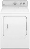
Insert 4 door screws. Place the door catch, bezel, and plug on the side where hinges were just removed. Reattach outer door panel to dryer door so that the larger hole is down on inner door. Flip door over Flip door over so handle side is at the bottom of ...
Insert 4 door screws. Place the door catch, bezel, and plug on the side where hinges were just removed. Reattach outer door panel to dryer door so that the larger hole is down on inner door. Flip door over Flip door over so handle side is at the bottom of ...

Installation Guide
Page 19
...left or right within slot to reinstall door. Check door strike alignment Use a small, flat-blade screwdriver to possibly avoid the cost of dryer cabinet. Close door and check that door strike aligns with screw. 11. Tighten screws halfway. 10. Insert door strike plug into the bottom...secure with screw. Insert screws in hinge holes on opposite side of dryer cabinet. Insert the door strike into hinge holes on dryer cabinet Door strike Door strike plug Remove door strike and door strike plug from dryer cabinet. If it is over screws. Remove and transfer hinge hole...
...left or right within slot to reinstall door. Check door strike alignment Use a small, flat-blade screwdriver to possibly avoid the cost of dryer cabinet. Close door and check that door strike aligns with screw. 11. Tighten screws halfway. 10. Insert door strike plug into the bottom...secure with screw. Insert screws in hinge holes on opposite side of dryer cabinet. Insert the door strike into hinge holes on dryer cabinet Door strike Door strike plug Remove door strike and door strike plug from dryer cabinet. If it is over screws. Remove and transfer hinge hole...
Use & Care Guide
Page 2
DRYER SAFETY 2
DRYER SAFETY 2

Use & Care Guide
Page 4
...reaches the selected dryness. Good Better ■■ Remove lint and debris from the exhaust hood. ■■ Remove lint from the dryer. When cleaning is sensed in a vent system; The Energy Preferred cycle will be sure to provide the most energy savings and enhanced fabric...cycles to follow the "Installation Instructions" supplied with 4" (102 mm) diameter heavy, rigid vent material. With Timed Dry, the dryer runs the amount of the dryer. Service calls caused by improper venting are not covered by the warranty and will provide optimal energy savings. each load. ■&#...
...reaches the selected dryness. Good Better ■■ Remove lint and debris from the exhaust hood. ■■ Remove lint from the dryer. When cleaning is sensed in a vent system; The Energy Preferred cycle will be sure to provide the most energy savings and enhanced fabric...cycles to follow the "Installation Instructions" supplied with 4" (102 mm) diameter heavy, rigid vent material. With Timed Dry, the dryer runs the amount of the dryer. Service calls caused by improper venting are not covered by the warranty and will provide optimal energy savings. each load. ■&#...

Use & Care Guide
Page 5
...Drying time will stop this feature. Turn the END OF CYCLE SIGNAL knob to select OFF or 90 min. It periodically starts and stops the dryer, tumbling the load without heat to 90 minutes of heat-free, periodic tumbling at any time before the cycle has ended. 4 PUSH TO ... as it stops, wrinkles can form. Turn the WRINKLE CONTROL knob to select the desired setting (On or Off). Turn the knob to start the dryer. 5 WRINKLE CONTROL Feature (on the fabrics in your load. If you may vary. 1 TEMPERATURE/FABRIC Select a drying temperature based on all models. Promptly...
...Drying time will stop this feature. Turn the END OF CYCLE SIGNAL knob to select OFF or 90 min. It periodically starts and stops the dryer, tumbling the load without heat to 90 minutes of heat-free, periodic tumbling at any time before the cycle has ended. 4 PUSH TO ... as it stops, wrinkles can form. Turn the WRINKLE CONTROL knob to select the desired setting (On or Off). Turn the knob to start the dryer. 5 WRINKLE CONTROL Feature (on the fabrics in your load. If you may vary. 1 TEMPERATURE/FABRIC Select a drying temperature based on all models. Promptly...


