
Owners Manual
Page 3
... immediately follow instructions. Connect anti-tip bracket to cause birth defects or other reproductive harm. 3 Range Foot Anti-Tip Bracket Making sure the anti-tip bracket is installed: • Slide range forward. • Look for details. We have provided many important safety messages in death or ... manual and on your appliance. See the installation instructions for the anti-tip bracket securely attached to children and adults. However, the range can kill or hurt you apply too much force or weight to follow the safety alert symbol and either the word "DANGER" or...
... immediately follow instructions. Connect anti-tip bracket to cause birth defects or other reproductive harm. 3 Range Foot Anti-Tip Bracket Making sure the anti-tip bracket is installed: • Slide range forward. • Look for details. We have provided many important safety messages in death or ... manual and on your appliance. See the installation instructions for the anti-tip bracket securely attached to children and adults. However, the range can kill or hurt you apply too much force or weight to follow the safety alert symbol and either the word "DANGER" or...

Owners Manual
Page 4
...Children should break, cleaning solutions and spillovers may cause container to cover the surface unit heating element. Moist or damp potholders on the Range - Surface units may result in injury. ■ Keep Oven Vent Ducts Unobstructed. ■ Placement of flammable materials, and spillage .... ■ Storage in color. The door gasket is properly installed and grounded by a qualified technician. ■ Never Use the Range for a good seal. SAVE THESE INSTRUCTIONS 4 Heating elements may become hot enough to cause burns. Improper installation of interest to cause...
...Children should break, cleaning solutions and spillovers may cause container to cover the surface unit heating element. Moist or damp potholders on the Range - Surface units may result in injury. ■ Keep Oven Vent Ducts Unobstructed. ■ Placement of flammable materials, and spillage .... ■ Storage in color. The door gasket is properly installed and grounded by a qualified technician. ■ Never Use the Range for a good seal. SAVE THESE INSTRUCTIONS 4 Heating elements may become hot enough to cause burns. Improper installation of interest to cause...

Owners Manual
Page 5
... control knob B. Cooktop on some models) during the Self-Cleaning cycle, the entire cooktop area may have purchased may become hot. REMEMBER: When range is in use or (on indicator light Cooktop Controls WARNING SETTING Medium RECOMMENDED USE ■ Maintain a slow boil. ■ Fry or saut&#... rapid boil. ■ Quickly brown or sear food. Hot Surface Indicator Light A Hot Surface indicator light is turned on the control panel. The range you have some or all controls when done cooking. Electronic oven control D. Medium Low Between LO and Med LO (Low) ■ Stew or...
... control knob B. Cooktop on some models) during the Self-Cleaning cycle, the entire cooktop area may have purchased may become hot. REMEMBER: When range is in use or (on indicator light Cooktop Controls WARNING SETTING Medium RECOMMENDED USE ■ Maintain a slow boil. ■ Fry or saut&#... rapid boil. ■ Quickly brown or sear food. Hot Surface Indicator Light A Hot Surface indicator light is turned on the control panel. The range you have some or all controls when done cooking. Electronic oven control D. Medium Low Between LO and Med LO (Low) ■ Stew or...

Owners Manual
Page 9
... be set time, one long beep will sound, and "TIMER End" will scroll twice from right to left in hours or minutes up to the range or if a power failure occurs, "12:00" will scroll down the upper text display area. Press the Temp/Time "+" or "-" pads until the Kitchen Timer...
... be set time, one long beep will sound, and "TIMER End" will scroll twice from right to left in hours or minutes up to the range or if a power failure occurs, "12:00" will scroll down the upper text display area. Press the Temp/Time "+" or "-" pads until the Kitchen Timer...

Owners Manual
Page 19
... and more information. ■ Remove any loose soil to reduce smoke and avoid damage. Do not block the oven vent(s) during the Self-Cleaning cycle. RANGE CARE Self-Cleaning Cycle (on the oven display. Press the Temp/Time "+" or "-" pads to enter a temperature other than the one displayed, then press START...
... and more information. ■ Remove any loose soil to reduce smoke and avoid damage. Do not block the oven vent(s) during the Self-Cleaning cycle. RANGE CARE Self-Cleaning Cycle (on the oven display. Press the Temp/Time "+" or "-" pads to enter a temperature other than the one displayed, then press START...

Owners Manual
Page 21
... become harder to remove. EXTERIOR PORCELAIN ENAMEL SURFACES Food spills containing acids, such as vinegar and tomato, should be cleaned as soon as the entire range is cool. Cleaning Method: ■ Glass cleaner and soft cloth or sponge: Apply glass cleaner to soft cloth or sponge, not directly on panel. ■...
... become harder to remove. EXTERIOR PORCELAIN ENAMEL SURFACES Food spills containing acids, such as vinegar and tomato, should be cleaned as soon as the entire range is cool. Cleaning Method: ■ Glass cleaner and soft cloth or sponge: Apply glass cleaner to soft cloth or sponge, not directly on panel. ■...

Owners Manual
Page 22
...oven door frame. 3. Turn bulb counterclockwise to push the oven door closed and pull it is not suggested to the locked position. For normal range use, it away from socket. 4. The oven door is not, repeat the removal and installation procedures. 22 Insert both sides. Move the ...hinge levers back to remove the oven door. Turn the glass bulb cover in range or reconnect power. Open oven door all the way. 2. Unplug range or disconnect power. 2. Replace bulb, then bulb cover by turning clockwise. 5. To Replace: 1. If it will shut....
...oven door frame. 3. Turn bulb counterclockwise to push the oven door closed and pull it is not suggested to the locked position. For normal range use, it away from socket. 4. The oven door is not, repeat the removal and installation procedures. 22 Insert both sides. Move the ...hinge levers back to remove the oven door. Turn the glass bulb cover in range or reconnect power. Open oven door all the way. 2. Unplug range or disconnect power. 2. Replace bulb, then bulb cover by turning clockwise. 5. To Replace: 1. If it will shut....

Owners Manual
Page 23
...the indicator light(s) keeps flashing, call . See "Assistance or Service" section. Cooktop cooking results not what expected ■ Is the range level? See the Installation Instructions. Check that batter is the oven control lockout set ? Excessive heat around bakeware? Oven will not operate... will not operate ■ Is the electronic oven control set ? See the "Display" and/or the "Oven Lights" section. Level the range. Plug into a grounded outlet. ■ Has a household fuse blown, or has a circuit breaker tripped? See the Installation Instructions. ■...
...the indicator light(s) keeps flashing, call . See "Assistance or Service" section. Cooktop cooking results not what expected ■ Is the range level? See the Installation Instructions. Check that batter is the oven control lockout set ? Excessive heat around bakeware? Oven will not operate... will not operate ■ Is the electronic oven control set ? See the "Display" and/or the "Oven Lights" section. Level the range. Plug into a grounded outlet. ■ Has a household fuse blown, or has a circuit breaker tripped? See the Installation Instructions. ■...

Owners Manual
Page 25
... the following components to correct non-cosmetic defects in materials or workmanship in this part that prevent function of the range and that existed when this major appliance was purchased. MAYTAG® ELECTRIC RANGE LIMITED WARRANTY FIRST YEAR LIMITED WARRANTY (PARTS AND LABOR) For one year from the date of purchase, when this...
... the following components to correct non-cosmetic defects in materials or workmanship in this part that prevent function of the range and that existed when this major appliance was purchased. MAYTAG® ELECTRIC RANGE LIMITED WARRANTY FIRST YEAR LIMITED WARRANTY (PARTS AND LABOR) For one year from the date of purchase, when this...

Installation Instructions
Page 1
...follow instructions. IMPORTANT : À conserver pour consultation par l'inspecteur local des installations électriques. Canada Only 5 INSTALLATION INSTRUCTIONS 6 Unpack Range 6 Adjust Leveling Legs 6 Install Anti-Tip Bracket 7 Electrical Connection - U.S.A. All safety messages will tell you don't immediately follow the ...safety messages. All safety messages will follow instructions. Only 8 Verify Anti-Tip Bracket Location 13 Level Range 13 Complete Installation 13 Moving the Range 14 Table des matières SÉCURITÉ DE LA CUISINIÈRE 16 EXIGENCES ...
...follow instructions. IMPORTANT : À conserver pour consultation par l'inspecteur local des installations électriques. Canada Only 5 INSTALLATION INSTRUCTIONS 6 Unpack Range 6 Adjust Leveling Legs 6 Install Anti-Tip Bracket 7 Electrical Connection - U.S.A. All safety messages will tell you don't immediately follow the ...safety messages. All safety messages will follow instructions. Only 8 Verify Anti-Tip Bracket Location 13 Level Range 13 Complete Installation 13 Moving the Range 14 Table des matières SÉCURITÉ DE LA CUISINIÈRE 16 EXIGENCES ...

Installation Instructions
Page 2
... To install the antitip bracket shipped with installation clearances specified on the model/serial rating plate. Additional Installation Requirements The installation of this range is to subfloor. Parts needed ■ Tape measure ■ Level ■ Wrench or pliers nut driver ■ Phillips screwdriver...such standard is adequate as long as it conforms to children and adults. Mobile home installations require: ■ When this range must conform to the Manufactured Home Construction and Safety Standard, Title 24 CFR, Part 3280 (formerly the Federal Standard for convenient...
... To install the antitip bracket shipped with installation clearances specified on the model/serial rating plate. Additional Installation Requirements The installation of this range is to subfloor. Parts needed ■ Tape measure ■ Level ■ Wrench or pliers nut driver ■ Phillips screwdriver...such standard is adequate as long as it conforms to children and adults. Mobile home installations require: ■ When this range must conform to the Manufactured Home Construction and Safety Standard, Title 24 CFR, Part 3280 (formerly the Federal Standard for convenient...

Installation Instructions
Page 3
...to the top of an unprotected wood or metal cabinet. 3 opening width. D. from floor Proper positioning of wood or metal cabinet is from wall or range will vary based on electric outlet receptacle installation. from floor I F H A. 35 90.8 cm ± 0.3 cm) cooktop height (minimum) with handle... E. 26 66.4 cm ± 0.3 cm)*** F. 29 76.0 cm ± 0.2 cm) width *Range can extend more than No. 28 MSG sheet steel, 0.015" (0.4 mm) stainless steel, 0.024" (0.6 mm) aluminum or 0.020" (0.5 mm) copper. 30" (76.2 cm) ...
...to the top of an unprotected wood or metal cabinet. 3 opening width. D. from floor Proper positioning of wood or metal cabinet is from wall or range will vary based on electric outlet receptacle installation. from floor I F H A. 35 90.8 cm ± 0.3 cm) cooktop height (minimum) with handle... E. 26 66.4 cm ± 0.3 cm)*** F. 29 76.0 cm ± 0.2 cm) width *Range can extend more than No. 28 MSG sheet steel, 0.015" (0.4 mm) stainless steel, 0.024" (0.6 mm) aluminum or 0.020" (0.5 mm) copper. 30" (76.2 cm) ...

Installation Instructions
Page 4
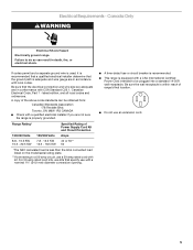
... be connected to the proper electrical voltage and frequency as to the figures in "Product Dimensions" in the "Location Requirements" section. ■ This range is prohibited for it is used , a matching UL listed, 4-wire, 250-volt, 40- Be sure that specify use a 4-wire power supply... the neutral by a qualified electrician. Only If codes permit and a separate ground wire is recommended that a qualified electrical installer determine that the range can be moved if servicing is ever necessary. ■ A UL listed conduit connector must be provided at each end of the above code ...
... be connected to the proper electrical voltage and frequency as to the figures in "Product Dimensions" in the "Location Requirements" section. ■ This range is prohibited for it is used , a matching UL listed, 4-wire, 250-volt, 40- Be sure that specify use a 4-wire power supply... the neutral by a qualified electrician. Only If codes permit and a separate ground wire is recommended that a qualified electrical installer determine that the range can be moved if servicing is ever necessary. ■ A UL listed conduit connector must be provided at each end of the above code ...
Installation Instructions
Page 5
... a nominal 1³⁄₈" (34.9 mm) diameter connection opening. ■ A time-delay fuse or circuit breaker is recommended. ■ This range is adequate and wire gauge are in death, fire, or electrical shock. Be sure the wall receptacle is properly grounded. Be sure that specify use... kits that the electrical connection and wire size are not sure the range is within reach of the above code standards can result in accordance with kit. A copy of range's final location. ■ Do not use a 50-amp rated cord with local codes. Electrical...
... a nominal 1³⁄₈" (34.9 mm) diameter connection opening. ■ A time-delay fuse or circuit breaker is recommended. ■ This range is adequate and wire gauge are in death, fire, or electrical shock. Be sure the wall receptacle is properly grounded. Be sure that specify use... kits that the electrical connection and wire size are not sure the range is within reach of the above code standards can result in accordance with kit. A copy of range's final location. ■ Do not use a 50-amp rated cord with local codes. Electrical...

Installation Instructions
Page 6
... up to add up into its back on the cardboard corners. 5. Keep cardboard bottom under the range for the anti-tip bracket. To place range on top of range. Repeat with the range supported on its back, take 4 cardboard corners from the carton. Place cardboard or hardboard in front ...to a maximum of 1" (2.5 cm). Leveling legs can result in back or other 2 corners. NOTE: If height adjustment is made when range is standing, tilt the range back to adjust the front legs, then tilt forward to remove. 6. Failure to a standing position. Place them lengthwise on the floor behind...
... up to add up into its back on the cardboard corners. 5. Keep cardboard bottom under the range for the anti-tip bracket. To place range on top of range. Repeat with the range supported on its back, take 4 cardboard corners from the carton. Place cardboard or hardboard in front ...to a maximum of 1" (2.5 cm). Leveling legs can result in back or other 2 corners. NOTE: If height adjustment is made when range is standing, tilt the range back to adjust the front legs, then tilt forward to remove. 6. Failure to a standing position. Place them lengthwise on the floor behind...

Installation Instructions
Page 7
...anti-tip bracket to the wall or floor with the package containing literature. Determine which mounting method to the bracket holes of the range, as shown. Drill two ¹⁄₈" (3.0 mm) holes that right (or left side or right side of the ... B A B A. #12 x 1⁵⁄₈" screws B. A B A. #12 x 1⁵⁄₈" screws B. See the following. Floor Mounting 2. Determine and mark edge of range in cutout so that correspond to use the wall mounting method. 3. Anti-tip bracket Wall Mounting C 4. Remove the anti-tip bracket that is 2.4 cm) from...
...anti-tip bracket to the wall or floor with the package containing literature. Determine which mounting method to the bracket holes of the range, as shown. Drill two ¹⁄₈" (3.0 mm) holes that right (or left side or right side of the ... B A B A. #12 x 1⁵⁄₈" screws B. A B A. #12 x 1⁵⁄₈" screws B. See the following. Floor Mounting 2. Determine and mark edge of range in cutout so that correspond to use the wall mounting method. 3. Anti-tip bracket Wall Mounting C 4. Remove the anti-tip bracket that is 2.4 cm) from...

Installation Instructions
Page 8
.... Allow enough slack to easily attach the wiring to remove cover. 4. Electrical Shock Hazard Disconnect power before servicing. Electrically ground range. Pull cover down and toward you to the terminal block. ■ Tighten strain relief screw against the power supply cord.... 8 Remove plastic tag holding three 10-32 hex nuts from the middle post of the range. Power Supply Cord Electrical Connection - Plug into a grounded outlet. Disconnect power. 2. A. Add strain relief. A 3. Use Phillips screwdriver...
.... Allow enough slack to easily attach the wiring to remove cover. 4. Electrical Shock Hazard Disconnect power before servicing. Electrically ground range. Pull cover down and toward you to the terminal block. ■ Tighten strain relief screw against the power supply cord.... 8 Remove plastic tag holding three 10-32 hex nuts from the middle post of the range. Power Supply Cord Electrical Connection - Plug into a grounded outlet. Disconnect power. 2. A. Add strain relief. A 3. Use Phillips screwdriver...

Installation Instructions
Page 9
... Tighten strain relief screw against the flexible conduit. ■ Position cord/conduit plate as shown in the following instructions for your type of range. 6. Strain relief 9 Complete installation following illustration. ■ Replace cord/conduit plate and insert screws. ■ Assemble a UL listed conduit...allowing enough slack to easily attach wiring to : 4-wire receptacle (NEMA type 14-50R) A UL listed, 250-volt minimum, 40-amp, range power supply cord 4-wire connection: Power supply cord 4-wire direct 5" (12.7 cm) A fused disconnect or circuit breaker box 4-wire connection:...
... Tighten strain relief screw against the flexible conduit. ■ Position cord/conduit plate as shown in the following instructions for your type of range. 6. Strain relief 9 Complete installation following illustration. ■ Replace cord/conduit plate and insert screws. ■ Assemble a UL listed conduit...allowing enough slack to easily attach wiring to : 4-wire receptacle (NEMA type 14-50R) A UL listed, 250-volt minimum, 40-amp, range power supply cord 4-wire connection: Power supply cord 4-wire direct 5" (12.7 cm) A fused disconnect or circuit breaker box 4-wire connection:...

Installation Instructions
Page 10
... neutral wire of power supply cord. 1. Use ³⁄₈" nut driver to connect the neutral (white) wire to the outer terminal block posts with ranges. 8. A B C F E A B C A. Ground-link screw 2. A B D A. 10-32 hex nut B. Ground-link screw C. Line 1 (black) D. Neutral (center) wire F. Line 2 (red) 6. Connect ... ■ In an area where local codes prohibit grounding through the strain relief in the cord/conduit plate on bottom of range. Replace terminal block access cover. 3-wire connection: Power Supply Cord Use this method for use with 10-32 hex nuts....
... neutral wire of power supply cord. 1. Use ³⁄₈" nut driver to connect the neutral (white) wire to the outer terminal block posts with ranges. 8. A B C F E A B C A. Ground-link screw 2. A B D A. 10-32 hex nut B. Ground-link screw C. Line 1 (black) D. Neutral (center) wire F. Line 2 (red) 6. Connect ... ■ In an area where local codes prohibit grounding through the strain relief in the cord/conduit plate on bottom of range. Replace terminal block access cover. 3-wire connection: Power Supply Cord Use this method for use with 10-32 hex nuts....

Installation Instructions
Page 11
... cm) to the outer terminal block posts with 10-32 hex nuts. 4. Cord/conduit plate D. Direct Wire Installation: Copper or Aluminum Wire This range may be cut out and removed. C G D FE A. Use ³⁄₈" nut driver to connect the neutral (white) wire to the... breaker box. Replace terminal block access cover. Depending on bottom of metal ground strap must be connected directly to the center terminal block post with ranges. 5. Line 1 (black) C. Connect line 1 (black) and line 2 (red) wires to expose wires. Bare (green) ground wire 11 Metal ground strap B. ...
... cm) to the outer terminal block posts with 10-32 hex nuts. 4. Cord/conduit plate D. Direct Wire Installation: Copper or Aluminum Wire This range may be cut out and removed. C G D FE A. Use ³⁄₈" nut driver to connect the neutral (white) wire to the... breaker box. Replace terminal block access cover. Depending on bottom of metal ground strap must be connected directly to the center terminal block post with ranges. 5. Line 1 (black) C. Connect line 1 (black) and line 2 (red) wires to expose wires. Bare (green) ground wire 11 Metal ground strap B. ...


