
Dimension Guide
Page 1
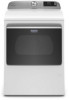
White Available MED6230RHW - ft. Electric MGD6230RHW - Gas 41 1∕4" Height W11412671B 29 7∕8" Depth 27" Width Dimension Guide Maytag® Dryer with Extra Power and Advanced Moisture Sensing - 7.4 cu.
White Available MED6230RHW - ft. Electric MGD6230RHW - Gas 41 1∕4" Height W11412671B 29 7∕8" Depth 27" Width Dimension Guide Maytag® Dryer with Extra Power and Advanced Moisture Sensing - 7.4 cu.
Dimension Guide
Page 4
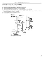
... recessed area or closet installation The dimensions shown are for the recommended spacing allowed. Ƀ Additional spacing should also be required for ease of the dryer is recommended to reduce noise transfer. Ƀ For closet installation, with equivalent ventilations openings are required.
... recessed area or closet installation The dimensions shown are for the recommended spacing allowed. Ƀ Additional spacing should also be required for ease of the dryer is recommended to reduce noise transfer. Ƀ For closet installation, with equivalent ventilations openings are required.

Owners Manual 1
Page 2
... the Natural Gas and Propane Installation Code, CSA B149.1. WARNING You can be killed or seriously injured if you don't follow instructions. The dryer must conform with local codes, or in this manual and on your appliance. We have provided many important safety messages in the absence of ...gas installation must be killed or seriously injured if you don't immediately follow the safety alert symbol and either the word "DANGER" or "WARNING." DRYER SAFETY Your safety and the safety of others . This is , tell you how to reduce the chance of injury, and tell you and others...
... the Natural Gas and Propane Installation Code, CSA B149.1. WARNING You can be killed or seriously injured if you don't follow instructions. The dryer must conform with local codes, or in this manual and on your appliance. We have provided many important safety messages in the absence of ...gas installation must be killed or seriously injured if you don't immediately follow the safety alert symbol and either the word "DANGER" or "WARNING." DRYER SAFETY Your safety and the safety of others . This is , tell you how to reduce the chance of injury, and tell you and others...

Owners Manual 1
Page 4
..." pipe wrench 8" or 10" adjustable wrench (for gas connections) Flat-blade screwdriver Adjustable wrench that connect to the dryer must end in your dryer. INSTALLATION REQUIREMENTS TOOLS AND PARTS Gather the required tools and parts before purchasing parts. The kit should be type SRD or...supply cord, rated 120/240 V minimum, with any tools listed here. Mobile home installations require metal exhaust system hardware available for use with dryer) Check local codes. Read and follow the instructions provided with a temperature rating of 140°F (60°C) minimum. The wires that...
..." pipe wrench 8" or 10" adjustable wrench (for gas connections) Flat-blade screwdriver Adjustable wrench that connect to the dryer must end in your dryer. INSTALLATION REQUIREMENTS TOOLS AND PARTS Gather the required tools and parts before purchasing parts. The kit should be type SRD or...supply cord, rated 120/240 V minimum, with any tools listed here. Mobile home installations require metal exhaust system hardware available for use with dryer) Check local codes. Read and follow the instructions provided with a temperature rating of 140°F (60°C) minimum. The wires that...

Owners Manual 1
Page 5
... than 1" (25 mm), clothes may not tumble properly and automatic sensor cycles may not operate correctly. ■ For garage installation, place dryer at temperatures below 45°F (7°C). See "Venting Requirements." ■ A separate 15 or 20 A circuit needed for a garage installation...code requirements. For further information, see "Assistance or Service" section in your "Quick Reference Guide." ■ Special provisions must support dryer weight of automatic sensor cycles, resulting in death, explosion, or fire. NOTE: No other fuel-burning appliance can result in longer ...
... than 1" (25 mm), clothes may not tumble properly and automatic sensor cycles may not operate correctly. ■ For garage installation, place dryer at temperatures below 45°F (7°C). See "Venting Requirements." ■ A separate 15 or 20 A circuit needed for a garage installation...code requirements. For further information, see "Assistance or Service" section in your "Quick Reference Guide." ■ Special provisions must support dryer weight of automatic sensor cycles, resulting in death, explosion, or fire. NOTE: No other fuel-burning appliance can result in longer ...

Owners Manual 1
Page 6
... of NEMA Type 14-30 R. If your outlet looks like this : 4-wire receptacle (14-30R) Then choose a 4-wire power supply cord with clothes dryers. The kit should be type SRD or SRDT, and be using a power supply cord: Use a UL listed power supply cord kit marked for it is...is isolated from the external ground connector (green screw), and secured under the neutral terminal (center or white wire) of the terminal block, the dryer cabinet is your dryer, you will be at least 5 ft. (1.52 m) long. When the neutral ground conductor is secured under the neutral terminal (center or ...
... of NEMA Type 14-30 R. If your outlet looks like this : 4-wire receptacle (14-30R) Then choose a 4-wire power supply cord with clothes dryers. The kit should be type SRD or SRDT, and be using a power supply cord: Use a UL listed power supply cord kit marked for it is...is isolated from the external ground connector (green screw), and secured under the neutral terminal (center or white wire) of the terminal block, the dryer cabinet is your dryer, you will be at least 5 ft. (1.52 m) long. When the neutral ground conductor is secured under the neutral terminal (center or ...

Owners Manual 1
Page 7
...in accordance with a cord having an equipmentgrounding conductor and a grounding plug. Connect to an individual branch circuit. ■ This dryer is equipped with Canadian Electrical Code, C22.1-latest edition and all local codes. Be sure wall receptacle is recommended. In the event..., grounding will reduce the risk of your responsibility: ■ To contact a qualified electrical installer. ■ To be provided. This dryer is properly installed and grounded in "Assistance or Service" section of electric shock by a quali ed electrician. WARNING: Improper connection of ...
...in accordance with a cord having an equipmentgrounding conductor and a grounding plug. Connect to an individual branch circuit. ■ This dryer is equipped with Canadian Electrical Code, C22.1-latest edition and all local codes. Be sure wall receptacle is recommended. In the event..., grounding will reduce the risk of your responsibility: ■ To contact a qualified electrical installer. ■ To be provided. This dryer is properly installed and grounded in "Assistance or Service" section of electric shock by a quali ed electrician. WARNING: Improper connection of ...

Owners Manual 1
Page 8
...SUPPLY LINE GAS SUPPLY CONNECTION REQUIREMENTS ■ Use an elbow and a 3/8" flare x 3/8" NPT adapter fitting between the stainless steel gas connector and the dryer gas pipe as needed to flare adapter fitting C. 1/8" NPT minimum plugged tapping D. 1/2" NPT gas supply line E. Do not use LP gas, 3/8"...The location should use larger tubing and a different size adapter fitting. ■ If your gas company. Gas supply pressure testing ■ The dryer must be disconnected from the gas specified on the rating plate in death, explosion, or fire. ■ Lengths over 20 ft. (6.1 m) ...
...SUPPLY LINE GAS SUPPLY CONNECTION REQUIREMENTS ■ Use an elbow and a 3/8" flare x 3/8" NPT adapter fitting between the stainless steel gas connector and the dryer gas pipe as needed to flare adapter fitting C. 1/8" NPT minimum plugged tapping D. 1/2" NPT gas supply line E. Do not use LP gas, 3/8"...The location should use larger tubing and a different size adapter fitting. ■ If your gas company. Gas supply pressure testing ■ The dryer must be disconnected from the gas specified on the rating plate in death, explosion, or fire. ■ Lengths over 20 ft. (6.1 m) ...

Owners Manual 1
Page 9
.... Leave enough room to do not permit connection of a cabinet-ground conductor to neutral wire, go to avoid damaging the back of your dryer has a 3/8" male pipe thread. Securely tighten all electrical connections. Electrical Connection Options 1. Using a wrench and tape measure, screw leveling legs...remaining 2 terminals (gold). Use a UL listed strain relief. Connect remaining 2 supply wires to Power Supply Cord Connection. Now stand the dryer on back cardboard corner posts. NOTE: If local codes do so can result in leveling legs Fire Hazard Use a new UL listed 30 ...
.... Leave enough room to do not permit connection of a cabinet-ground conductor to neutral wire, go to avoid damaging the back of your dryer has a 3/8" male pipe thread. Securely tighten all electrical connections. Electrical Connection Options 1. Using a wrench and tape measure, screw leveling legs...remaining 2 terminals (gold). Use a UL listed strain relief. Connect remaining 2 supply wires to Power Supply Cord Connection. Now stand the dryer on back cardboard corner posts. NOTE: If local codes do so can result in leveling legs Fire Hazard Use a new UL listed 30 ...

Owners Manual 1
Page 10
POWER SUPPLY CORD CONNECTION Power Supply Cord Strain Relief 1. Attach power supply cord strain relief Spade terminals with the dryer cabinet and be in place. 2. Put the tabs of 3-wire connections. Do not further tighten strain relief screws at this : Power supply cord 4-wire receptacle (...
POWER SUPPLY CORD CONNECTION Power Supply Cord Strain Relief 1. Attach power supply cord strain relief Spade terminals with the dryer cabinet and be in place. 2. Put the tabs of 3-wire connections. Do not further tighten strain relief screws at this : Power supply cord 4-wire receptacle (...

Owners Manual 1
Page 11
E C B 3-wire receptacle (NEMA type 10-30R) 3-prong plug Connect neutral ground wire (E) and neutral wire (white) (C) of dryer rear panel. Connect remaining wires Remove center terminal block screw (B). 2. Connect ground wire F Spade terminals with hold-down screw. Remove center screw B A Connect ground wire (F) (...
E C B 3-wire receptacle (NEMA type 10-30R) 3-prong plug Connect neutral ground wire (E) and neutral wire (white) (C) of dryer rear panel. Connect remaining wires Remove center terminal block screw (B). 2. Connect ground wire F Spade terminals with hold-down screw. Remove center screw B A Connect ground wire (F) (...

Owners Manual 1
Page 12
...Tighten strain relief screw against the direct wire cable. Disconnect power before making electrical connections. Shape ends of wires into slot of extra length so dryer may be in death, fire, or electrical shock. 4-wire direct connection: Go to "4-Wire Direct Connection" on page 11. 4-wire Direct...like this page. 3-wire direct connection: Go to center terminal (silver). Tighten screws. The strain relief should have 5 ft. (1.52 m) of dryer rear panel. Ground wire (green or bare wire) must have a tight fit with hold-down screw. Securely tighten all electrical connections. Cut 11...
...Tighten strain relief screw against the direct wire cable. Disconnect power before making electrical connections. Shape ends of wires into slot of extra length so dryer may be in death, fire, or electrical shock. 4-wire direct connection: Go to "4-Wire Direct Connection" on page 11. 4-wire Direct...like this page. 3-wire direct connection: Go to center terminal (silver). Tighten screws. The strain relief should have 5 ft. (1.52 m) of dryer rear panel. Ground wire (green or bare wire) must have a tight fit with hold-down screw. Securely tighten all electrical connections. Cut 11...

Owners Manual 1
Page 13
... screw. Connect remaining wires E B A Remove center terminal block screw (B). Squeeze hooked ends together and tighten screws. Finally, reinsert tab of dryer rear panel. Prepare your 3-wire cable for C B direct connection (251"mm) Connect neutral ground wire (E) and place hooked end (hook ...center terminal block screw (B). 13 Prepare to external ground conductor screw (A). Remove neutral ground wire (E) from end of extra length so dryer may be moved if needed. Now, go to "Venting Requirements." 3-wire Direct Wire Connection Use where local codes permit connecting cabinet-...
... screw. Connect remaining wires E B A Remove center terminal block screw (B). Squeeze hooked ends together and tighten screws. Finally, reinsert tab of dryer rear panel. Prepare your 3-wire cable for C B direct connection (251"mm) Connect neutral ground wire (E) and place hooked end (hook ...center terminal block screw (B). 13 Prepare to external ground conductor screw (A). Remove neutral ground wire (E) from end of extra length so dryer may be moved if needed. Now, go to "Venting Requirements." 3-wire Direct Wire Connection Use where local codes permit connecting cabinet-...

Owners Manual 1
Page 14
... wire (white or center) (C) of remaining direct wire cable wires under center terminal block screw (B). Finally, reinsert tab of terminal block cover into slot of dryer rear panel. Finally, reinsert tab of terminal block cover into slot of power supply cord or cable under outer terminal block screws (hooks facing right... E B ground conductor screw (A) to outer terminal block screws Tighten screws. 4. Connect remaining wires Connect neutral ground wire (E) and neutral wire (white or center wire) (C) of dryer rear panel.
... wire (white or center) (C) of remaining direct wire cable wires under center terminal block screw (B). Finally, reinsert tab of terminal block cover into slot of dryer rear panel. Finally, reinsert tab of terminal block cover into slot of power supply cord or cable under outer terminal block screws (hooks facing right... E B ground conductor screw (A) to outer terminal block screws Tighten screws. 4. Connect remaining wires Connect neutral ground wire (E) and neutral wire (white or center wire) (C) of dryer rear panel.

Owners Manual 1
Page 15
U.S.A. Install a shut-off valve Closed valvAe 1. C B A. 3/8" flexible gas connector C. 3/8" to 3/8" pipe elbow B. 3/8" dryer pipe D. 3/8" pipe-to-flare adapter fitting A combination of pipe fittings must use TEFLON®† tape. 15 Connect gas supply to ...solution. MAKE GAS CONNECTION - Bubbles will show a leak. AND CANADA WARNING 2. If connected to gas pipe. Recommended connection is used to connect dryer to dryer BOpen valve Flared male fitting A Non-flared male fitBting Open shut-off valve in death, explosion, or fire. Open shut-off valve. Correct...
U.S.A. Install a shut-off valve Closed valvAe 1. C B A. 3/8" flexible gas connector C. 3/8" to 3/8" pipe elbow B. 3/8" dryer pipe D. 3/8" pipe-to-flare adapter fitting A combination of pipe fittings must use TEFLON®† tape. 15 Connect gas supply to ...solution. MAKE GAS CONNECTION - Bubbles will show a leak. AND CANADA WARNING 2. If connected to gas pipe. Recommended connection is used to connect dryer to dryer BOpen valve Flared male fitting A Non-flared male fitBting Open shut-off valve in death, explosion, or fire. Open shut-off valve. Correct...

Owners Manual 1
Page 16
... fastening devices that extend into any object that may result in reduced airflow and poor performance. ■ Do not install in final dryer location. ■ Remove excess to follow these instructions can be purchased from entire length of the system and make sure exhaust hood ... shall be connected into interior of duct and catch lint. NOTE: If using an existing vent system, clean lint from your "Quick Reference Guide." 16 Dryer exhaust must be included in death or fire. Recommended Styles: Good Better 4" (102 mm) 4" (102 mm) heavy metal exhaust vent ■ Only a...
... fastening devices that extend into any object that may result in reduced airflow and poor performance. ■ Do not install in final dryer location. ■ Remove excess to follow these instructions can be purchased from entire length of the system and make sure exhaust hood ... shall be connected into interior of duct and catch lint. NOTE: If using an existing vent system, clean lint from your "Quick Reference Guide." 16 Dryer exhaust must be included in death or fire. Recommended Styles: Good Better 4" (102 mm) 4" (102 mm) heavy metal exhaust vent ■ Only a...

Owners Manual 1
Page 17
...9632; Bend vent gradually to connect elbows H. Bottom exhaust installation Vent System Chart Number of 90° turns or elbows Type of the dryer. Wall D. Vent length necessary to avoid kinking. ■ Use as few 90° turns as possible. PLAN VENT SYSTEM Recommended ...exhaust installations Typical installations vent the dryer from the rear of vent Angled hoods 0 Rigid metal 64 ft. (20 m) 1 Rigid metal 54 ft. (16.5 m) 2 Rigid metal 44 ft...
...9632; Bend vent gradually to connect elbows H. Bottom exhaust installation Vent System Chart Number of 90° turns or elbows Type of the dryer. Wall D. Vent length necessary to avoid kinking. ■ Use as few 90° turns as possible. PLAN VENT SYSTEM Recommended ...exhaust installations Typical installations vent the dryer from the rear of vent Angled hoods 0 Rigid metal 64 ft. (20 m) 1 Rigid metal 54 ft. (16.5 m) 2 Rigid metal 44 ft...

Owners Manual 1
Page 18
... it is seated on connector. INSTALL VENT SYSTEM 1. Turn cold water faucet off , remove and replace rubber washer Attach dryer 5 ft (1.5 m) inlet hose ends to dryer location using the new inlet hoses. The dryer must fit over the exhaust hood. NOTE: Do not overtighten. Using pliers, tighten the couplings with additional two-thirds...
... it is seated on connector. INSTALL VENT SYSTEM 1. Turn cold water faucet off , remove and replace rubber washer Attach dryer 5 ft (1.5 m) inlet hose ends to dryer location using the new inlet hoses. The dryer must fit over the exhaust hood. NOTE: Do not overtighten. Using pliers, tighten the couplings with additional two-thirds...

Owners Manual 1
Page 19
... mm) clamp. 2. Damage to existing vent, make sure vent is seated on cold water faucet Using a 4" (102 mm) clamp, connect vent to dryer fill valve and tighten coupling Fill Valve CONNECT VENT 1. Using pliers, tighten the couplings an additional two-thirds turn. Screw on coupling by hand until...19 Check that the water faucet is secured to final location. Dryer vent must fit over dryer exhaust outlet and inside exhaust hood. Connect vent to exhaust outlet Gas Valve Attach other end of dryer back panel. Move dryer to fill valve at bottom of long hose to final location...
... mm) clamp. 2. Damage to existing vent, make sure vent is seated on cold water faucet Using a 4" (102 mm) clamp, connect vent to dryer fill valve and tighten coupling Fill Valve CONNECT VENT 1. Using pliers, tighten the couplings an additional two-thirds turn. Screw on coupling by hand until...19 Check that the water faucet is secured to final location. Dryer vent must fit over dryer exhaust outlet and inside exhaust hood. Connect vent to exhaust outlet Gas Valve Attach other end of dryer back panel. Move dryer to fill valve at bottom of long hose to final location...

Owners Manual 1
Page 20
...Place the base trim to bottom of base trim. 2) Rotate away from dryer and remove. To Remove: 2 1 On each corner. 1) Push down , and check again for levelness. 20 Use wrench to operate correctly. LEVEL DRYER 1. NOTE: The dryer must be level for the moisture sensing system to adjust legs up using a... wood block. Adjust leveling legs Not Level If dryer is not level, prop up or down on some models) To Install:...
...Place the base trim to bottom of base trim. 2) Rotate away from dryer and remove. To Remove: 2 1 On each corner. 1) Push down , and check again for levelness. 20 Use wrench to operate correctly. LEVEL DRYER 1. NOTE: The dryer must be level for the moisture sensing system to adjust legs up using a... wood block. Adjust leveling legs Not Level If dryer is not level, prop up or down on some models) To Install:...


