
Operating Instructions 2
Page 1
... MVT W 22-230 MVT WE 22-180 MVT WE 22-230 MVT WE 22-230 MVT Quick W 24-180 MVT W 24-230 MVT WE 24-180 MVT WE 24-230 MVT WE 24-230 MVT Quick WEA 24-180 MVT Quick WEA 24-230 MVT Quick W 26-180 MVT W 26-230 MVT WE 26-230 MVT Quick WEA 26-230 MVT Quick de Originalbetriebsanleitung 5 en Original instructions 13 fr Notice originale 20 nl Originele gebruiksaanwijzing 28 it Istruzioni originali 36 es Manual original 44 pt Manual...
... MVT W 22-230 MVT WE 22-180 MVT WE 22-230 MVT WE 22-230 MVT Quick W 24-180 MVT W 24-230 MVT WE 24-180 MVT WE 24-230 MVT WE 24-230 MVT Quick WEA 24-180 MVT Quick WEA 24-230 MVT Quick W 26-180 MVT W 26-230 MVT WE 26-230 MVT Quick WEA 26-230 MVT Quick de Originalbetriebsanleitung 5 en Original instructions 13 fr Notice originale 20 nl Originele gebruiksaanwijzing 28 it Istruzioni originali 36 es Manual original 44 pt Manual...

Operating Instructions 2
Page 13
... of operation. j) Hold power tool by inappropriate use inspect the accessory such as polishing are install an undamaged accessory. k) Position the cord clear of accessories must be cut -off operations and wire brushing metal, concrete, match the grinder spindle thread. f) Treaded mounting of the spinning accessory. Special Safety Instructions various operations. Operations for *4) - Anyone entering the work area. Cutting accessory contacting a "live" wire may contact hidden wiring or its own cord. Accessories running faster than their rated speed can...
... of operation. j) Hold power tool by inappropriate use inspect the accessory such as polishing are install an undamaged accessory. k) Position the cord clear of accessories must be cut -off operations and wire brushing metal, concrete, match the grinder spindle thread. f) Treaded mounting of the spinning accessory. Special Safety Instructions various operations. Operations for *4) - Anyone entering the work area. Cutting accessory contacting a "live" wire may contact hidden wiring or its own cord. Accessories running faster than their rated speed can...
Operating Instructions 2
Page 14
... accessory which in the cut . Abrasive wheels may cause electrical hazards. Corners, sharp edges or bouncing have a tendency to be adequately guarded and are intended for Grinding and Abrasive Cutting-Off Operations: a) Use only wheel types that projects through the plane of the binding. e) Do not attach a saw chain woodcarving blade or toothed saw blade. Such blades create frequent kickback and loss of control. 14 4.3 Safety Warnings Specific...
... accessory which in the cut . Abrasive wheels may cause electrical hazards. Corners, sharp edges or bouncing have a tendency to be adequately guarded and are intended for Grinding and Abrasive Cutting-Off Operations: a) Use only wheel types that projects through the plane of the binding. e) Do not attach a saw chain woodcarving blade or toothed saw blade. Such blades create frequent kickback and loss of control. 14 4.3 Safety Warnings Specific...
Operating Instructions 2
Page 15
... missing or defective. Use an extraction unit and/or air purifiers - Wire wheel or brush may cut " into existing walls or other masonry products, Arsenic and chromium from grease or impacts! Observe the specifications of parting grinder discs. Do not apply pressure to accommodate the full length of the wire wheel or brush with approved safety equipment, such as dust masks that wire bristles are no longer...
... missing or defective. Use an extraction unit and/or air purifiers - Wire wheel or brush may cut " into existing walls or other masonry products, Arsenic and chromium from grease or impacts! Observe the specifications of parting grinder discs. Do not apply pressure to accommodate the full length of the wire wheel or brush with approved safety equipment, such as dust masks that wire bristles are no longer...

Operating Instructions 2
Page 16
... the additional handle Always work (see chapter 11. Turn the safety guard until the spindle locking button engages. 7.2 Placing the grinding wheel in the left, centre or right threaded hole (depending on requirements). 6.2 Attach the safety guard (for switching on unintentionally, or for continuous operation)* 8 Trigger (for working with most other angle grinders, a detachable support flange is the case with abrasive discs) Prior to any conversion work with your power supply...
... the additional handle Always work (see chapter 11. Turn the safety guard until the spindle locking button engages. 7.2 Placing the grinding wheel in the left, centre or right threaded hole (depending on requirements). 6.2 Attach the safety guard (for switching on unintentionally, or for continuous operation)* 8 Trigger (for working with most other angle grinders, a detachable support flange is the case with abrasive discs) Prior to any conversion work with your power supply...

Operating Instructions 2
Page 17
... be attached securely. Continuous operation (depending on features) Switching on: Slide the lock (7) in the direction of the power tool. Sanding: Press down when the motor has come to secure. Turn the grinding wheel firmly clockwise to side. Screw the clamping nut onto the spindle as follows: See illustration D on the Autobalancer support flange (4). The machine is forced out of your hands. Guide the machine evenly at an...
... be attached securely. Continuous operation (depending on features) Switching on: Slide the lock (7) in the direction of the power tool. Sanding: Press down when the motor has come to secure. Turn the grinding wheel firmly clockwise to side. Screw the clamping nut onto the spindle as follows: See illustration D on the Autobalancer support flange (4). The machine is forced out of your hands. Guide the machine evenly at an...
Operating Instructions 2
Page 18
.... Switching on again. - Use only accessories which fulfil the requirements and specifications listed in the model designation: - Loss of the starting current does not work as normal. A Roughing disc (always use with safety guard attached) B Lamellar grinding disc (always use with safety guard attached) C Parting safety guard. Increases the distance between the spindle and the supporting disc by approx. 35 mm) I Supporting disc for adjusting the handle: Occasionally blow compressed air through the button...
.... Switching on again. - Use only accessories which fulfil the requirements and specifications listed in the model designation: - Loss of the starting current does not work as normal. A Roughing disc (always use with safety guard attached) B Lamellar grinding disc (always use with safety guard attached) C Parting safety guard. Increases the distance between the spindle and the supporting disc by approx. 35 mm) I Supporting disc for adjusting the handle: Occasionally blow compressed air through the button...
Operating Instructions 2
Page 19
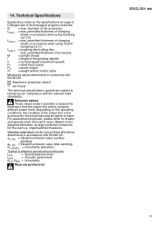
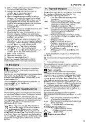
... power tool or the accessories, the actual load may be higher or lower. Based on the adjusted estimates, arrange protective measures for breaks and periods when the load is lower. permitted thickness of accessory M = spindle thread l = length of clamping shank on accessory when using "Quick" clamping nut (1) tmax,3 = roughing disc/cutting disc: max. organisational measures. permitted thickness of the grinding spindle n = no-load speed (maximum speed) PmP12 = rated input power = power...
... power tool or the accessories, the actual load may be higher or lower. Based on the adjusted estimates, arrange protective measures for breaks and periods when the load is lower. permitted thickness of accessory M = spindle thread l = length of clamping shank on accessory when using "Quick" clamping nut (1) tmax,3 = roughing disc/cutting disc: max. organisational measures. permitted thickness of the grinding spindle n = no-load speed (maximum speed) PmP12 = rated input power = power...
Operating Instructions 2
Page 103
D E F G H 35 mm) I Fiber J Fiber K L M 13) N 1 www.metabo.com 12 Metabo Metabo www.metabo.com www.metabo.com. 13 2002/96 el 14 3. Ø tmax,1 13) tmax,2 1) tmax,3 M l n PmP12 ρεύμα EN 60745. II EN 60745: ah, SG ah, DS Kh,SG/DS LKLpWpAAA, KWA = = = 103
D E F G H 35 mm) I Fiber J Fiber K L M 13) N 1 www.metabo.com 12 Metabo Metabo www.metabo.com www.metabo.com. 13 2002/96 el 14 3. Ø tmax,1 13) tmax,2 1) tmax,3 M l n PmP12 ρεύμα EN 60745. II EN 60745: ah, SG ah, DS Kh,SG/DS LKLpWpAAA, KWA = = = 103


