
Integration Guide
Page 22
... defaults, including the password. This resets the reader configuration to a Motorola approved power supply AC adapter (varies depending on the country). This flexibility allows it to external devices. XR450 Mono-Static Antenna Ports TX4 TX3 TX2 TX1 RX4 RX3 RX2 RX1 MONOSTATIC PORTS Figure 2-2 XR450 Mono-Static Ports The XR450 RFID reader configuration includes four mono-static antenna ports...
... defaults, including the password. This resets the reader configuration to a Motorola approved power supply AC adapter (varies depending on the country). This flexibility allows it to external devices. XR450 Mono-Static Antenna Ports TX4 TX3 TX2 TX1 RX4 RX3 RX2 RX1 MONOSTATIC PORTS Figure 2-2 XR450 Mono-Static Ports The XR450 RFID reader configuration includes four mono-static antenna ports...

Integration Guide
Page 23
...it will not be professionally installed. Installation and Communication 2 - 3 Installation CAUTION The XR Series RFID readers must be disturbed, bumped, or damaged. Position the reader on the wall or shelf, ensuring a minimum clearance of five inches on all sides. Remove the... of the antennas. • Ensure the power cord can reach the power source outlet. • Mount the reader onto a permanent fixture, such as a guide (see Figure 2-2). Sources of interference include generators, pumps, converters, non-interruptible power supplies, AC switching relays, light dimmers, and ...
...it will not be professionally installed. Installation and Communication 2 - 3 Installation CAUTION The XR Series RFID readers must be disturbed, bumped, or damaged. Position the reader on the wall or shelf, ensuring a minimum clearance of five inches on all sides. Remove the... of the antennas. • Ensure the power cord can reach the power source outlet. • Mount the reader onto a permanent fixture, such as a guide (see Figure 2-2). Sources of interference include generators, pumps, converters, non-interruptible power supplies, AC switching relays, light dimmers, and ...

Integration Guide
Page 25
... verify that the device is not operational. 2. Control the reader through a real time application. 3. To power down the reader: 1. Insert the power supply barrel connector into the reader power port, and rotate the connector to the reader. This indicates that there are no reads in place (see XR Series RFID Readers LEDs on page 1-5). The distance between the tag and...
... verify that the device is not operational. 2. Control the reader through a real time application. 3. To power down the reader: 1. Insert the power supply barrel connector into the reader power port, and rotate the connector to the reader. This indicates that there are no reads in place (see XR Series RFID Readers LEDs on page 1-5). The distance between the tag and...
Integration Guide
Page 26
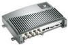
... configure it as the IP address) can be accessed using a Motorola AC power supply. See Chapter 3, Administrator Console. Power is necessary without connecting to Table A-3 on the COM port used to change reader settings). See Figure 2-2 on page 2-2. The Administrator Console login... computer, open an internet browser and enter the reader IP address. Connect a DB9 serial cable to a host or network using RS232: 1. 2 - 6 XR Series RFID Readers Integrator Guide Communications Connections Connect the reader to the reader RS232 port. The Ethernet connection allows access to ...
... configure it as the IP address) can be accessed using a Motorola AC power supply. See Chapter 3, Administrator Console. Power is necessary without connecting to Table A-3 on the COM port used to change reader settings). See Figure 2-2 on page 2-2. The Administrator Console login... computer, open an internet browser and enter the reader IP address. Connect a DB9 serial cable to a host or network using RS232: 1. 2 - 6 XR Series RFID Readers Integrator Guide Communications Connections Connect the reader to the reader RS232 port. The Ethernet connection allows access to ...
Integration Guide
Page 112
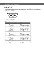
...GPIO Output - Bit 0 External GPIO Input - Bit 0 Ground External GPIO Output - Bit 3 External GPIO Output - Bit 0 5.4V Power Figure A-2 GPIO Pin Locations Table A-4 GPIO Pin Outs Pin # Pin Name 1 GND 2 EXT_GPIO_OUT4 3 EXT_GPIO_OUT2 4 EXT_GPIO_OUT0 5 EXT_GPIO_IN4 6 ...- Bit 1 External GPIO Input - Bit 0 External GPIO Input - Bit 0 External GPIO Input - A - 6 XR Series RFID Readers Integrator Guide GPIO Port Connections A GPIO port is supplied on a High Density DB15 female connector, see Figure A-2 for the pin locations and see Table A-4 for pin descriptions.
...GPIO Output - Bit 0 External GPIO Input - Bit 0 Ground External GPIO Output - Bit 3 External GPIO Output - Bit 0 5.4V Power Figure A-2 GPIO Pin Locations Table A-4 GPIO Pin Outs Pin # Pin Name 1 GND 2 EXT_GPIO_OUT4 3 EXT_GPIO_OUT2 4 EXT_GPIO_OUT0 5 EXT_GPIO_IN4 6 ...- Bit 1 External GPIO Input - Bit 0 External GPIO Input - Bit 0 External GPIO Input - A - 6 XR Series RFID Readers Integrator Guide GPIO Port Connections A GPIO port is supplied on a High Density DB15 female connector, see Figure A-2 for the pin locations and see Table A-4 for pin descriptions.

Integration Guide
Page 113
... • Update Method 2, Direct Connect Over the Ethernet Port The first option is typically used to perform the update procedure: • Reader with power supply • Laptop (or other host computer) • If using the LAN Update procedure, a Cat5 ethernet cable is required • ... Procedures Introduction This document is designed to the current settings and each can be upgraded independently. There are required to individually update a reader using the Direct-Connect update procedure a Cat5 Crossover cable is required • Serial cable (optional) • An ftp server on...
... • Update Method 2, Direct Connect Over the Ethernet Port The first option is typically used to perform the update procedure: • Reader with power supply • Laptop (or other host computer) • If using the LAN Update procedure, a Cat5 ethernet cable is required • ... Procedures Introduction This document is designed to the current settings and each can be upgraded independently. There are required to individually update a reader using the Direct-Connect update procedure a Cat5 Crossover cable is required • Serial cable (optional) • An ftp server on...