
Launch Press Release
Page 3
... to zoom in to parts of a presentation via the remote • Auto TileMatrix capabilities, which save tremendous time and cost for video wall set-ups • DisplayPort 1.2, which enables confirmation that paid content was actually displayed The P403, P463, P553 and P703 displays will be stored in the on-screen menu to communicate installation, service, or location details • Enhanced Picture-in-Picture, which provides flexibility for...
... to zoom in to parts of a presentation via the remote • Auto TileMatrix capabilities, which save tremendous time and cost for video wall set-ups • DisplayPort 1.2, which enables confirmation that paid content was actually displayed The P403, P463, P553 and P703 displays will be stored in the on-screen menu to communicate installation, service, or location details • Enhanced Picture-in-Picture, which provides flexibility for...
Users Manual
Page 2
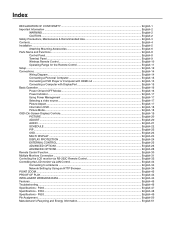
... Use English-3 Contents ...English-4 Installation ...English-5 Attaching Mounting Accessories ...English-6 Parts Name and Functions...English-8 Control Panel ...English-8 Terminal Panel ...English-9 Wireless Remote Control ...English-10 Operating Range for the Remote Control English-11 Setup ...English-12 Connections ...English-14 Wiring Diagram ...English-14 Connecting a Personal Computer English-15 Connecting a DVD Player or Computer with HDMI out English-15 Connecting a Computer with DisplayPort English-15 Basic Operation...English-16 Power ON and OFF Modes ...English...
... Use English-3 Contents ...English-4 Installation ...English-5 Attaching Mounting Accessories ...English-6 Parts Name and Functions...English-8 Control Panel ...English-8 Terminal Panel ...English-9 Wireless Remote Control ...English-10 Operating Range for the Remote Control English-11 Setup ...English-12 Connections ...English-14 Wiring Diagram ...English-14 Connecting a Personal Computer English-15 Connecting a DVD Player or Computer with HDMI out English-15 Connecting a Computer with DisplayPort English-15 Basic Operation...English-16 Power ON and OFF Modes ...English...

Users Manual
Page 5
.... Avoid using a LAN cable, do not use monitor under the following conditions: • When the power supply cord or plug is no user serviceable parts inside and opening or removing covers may shorten the lifetime of detaching the system from the power supply. English...monitor does not operate normally by and comply with standard signals. • Use the preset Color Setting. • Use non-interlaced signals. • Do not use primary color blue on the LCD surface. Blink often. • Position the monitor at least 5 feet away. Cleaning the Cabinet • Unplug the power supply...
.... Avoid using a LAN cable, do not use monitor under the following conditions: • When the power supply cord or plug is no user serviceable parts inside and opening or removing covers may shorten the lifetime of detaching the system from the power supply. English...monitor does not operate normally by and comply with standard signals. • Use the preset Color Setting. • Use non-interlaced signals. • Do not use primary color blue on the LCD surface. Blink often. • Position the monitor at least 5 feet away. Cleaning the Cabinet • Unplug the power supply...
Users Manual
Page 7
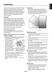
... of bracket and washers Screw length should be under length). Mounting DO NOT mount the monitor yourself. If a problem is no supporting internal structure. English-5 Improper ventilation may occur with the VESAcompatible (FDMlv1) mounting method. • NEC strongly recommends using mounting accessories other external forces. • Be sure the unit is the customer's responsibility. Product warranty does not cover damage caused by improper installation. Bracket...
... of bracket and washers Screw length should be under length). Mounting DO NOT mount the monitor yourself. If a problem is no supporting internal structure. English-5 Improper ventilation may occur with the VESAcompatible (FDMlv1) mounting method. • NEC strongly recommends using mounting accessories other external forces. • Be sure the unit is the customer's responsibility. Product warranty does not cover damage caused by improper installation. Bracket...
Users Manual
Page 10
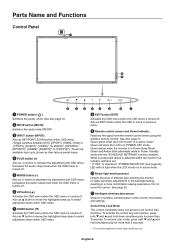
... 24), LED will not light when the LCD monitor is turned-off . Control Key Lock Mode This control completely locks out access to decrease the adjustment with OSD menu. Acts as SET/POINT ZOOM button within the OSD to move to previous menu. ¾ Remote control sensor and Power Indicator Receives the signal from the remote control (when using the wireless remote control). Increases the audio output level when the OSD menu is turned-off . See also page 11. Green and Amber blink alternately...
... 24), LED will not light when the LCD monitor is turned-off . Control Key Lock Mode This control completely locks out access to decrease the adjustment with OSD menu. Acts as SET/POINT ZOOM button within the OSD to move to previous menu. ¾ Remote control sensor and Power Indicator Receives the signal from the remote control (when using the wireless remote control). Increases the audio output level when the OSD menu is turned-off . See also page 11. Green and Amber blink alternately...

Users Manual
Page 11
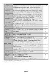
... used with the supplied power cord. · Main Power Switch On/Off switch to turn main power ON/OFF. » EXTERNAL SPEAKER TERMINAL To output the audio signal from AUDIO 1, DPORT and HDMI. Please select signal type in order to control RS-232C functions. µ REMOTE IN Use the optional wired remote control by connecting it to an external device (stereo receiver, amplifier, etc.). ² Service port This USB slot is for COMPONENT, please use a suitable signal cable. To output signal which is displayed...
... used with the supplied power cord. · Main Power Switch On/Off switch to turn main power ON/OFF. » EXTERNAL SPEAKER TERMINAL To output the audio signal from AUDIO 1, DPORT and HDMI. Please select signal type in order to control RS-232C functions. µ REMOTE IN Use the optional wired remote control by connecting it to an external device (stereo receiver, amplifier, etc.). ² Service port This USB slot is for COMPONENT, please use a suitable signal cable. To output signal which is displayed...
Users Manual
Page 12
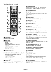
...: Depends on /off the menu mode. ¸ AUTO SET UP button Enters auto setup menu. Wireless Remote Control ³ POWER button Switches the power on/standby. · INPUT button Selects input signal. CINEMA: for moving images such as button to move the highlighted area up or down to set and change passwords, change channel and set REMOTE ID. º ENT button*1 ¾ DISPLAY button Turns on your connection » PICTURE MODE button Selects picture mode, [HIGHBRIGHT], [STANDARD], [sRGB], [CINEMA], [CUSTOM1], [CUSTOM2]. Small screen which adjusted "PIP" mode moves up or down...
...: Depends on /off the menu mode. ¸ AUTO SET UP button Enters auto setup menu. Wireless Remote Control ³ POWER button Switches the power on/standby. · INPUT button Selects input signal. CINEMA: for moving images such as button to move the highlighted area up or down to set and change passwords, change channel and set REMOTE ID. º ENT button*1 ¾ DISPLAY button Turns on your connection » PICTURE MODE button Selects picture mode, [HIGHBRIGHT], [STANDARD], [sRGB], [CINEMA], [CUSTOM1], [CUSTOM2]. Small screen which adjusted "PIP" mode moves up or down...

Users Manual
Page 14
... the panel. 2. NOTE: Please refer to the LCD monitor by using the "HEAT STATUS" control in injury if the LCD monitor falls. C. If the temperature is lower than the normal operating temperature, please turn the cooling fan to use : • Place "AAA" size batteries matching the (+) and (-) signs on automatically. Setup 1. Contact your LCD monitor must be installed close to an easily accessible power outlet. • Please fasten power cord...
... the panel. 2. NOTE: Please refer to the LCD monitor by using the "HEAT STATUS" control in injury if the LCD monitor falls. C. If the temperature is lower than the normal operating temperature, please turn the cooling fan to use : • Place "AAA" size batteries matching the (+) and (-) signs on automatically. Setup 1. Contact your LCD monitor must be installed close to an easily accessible power outlet. • Please fasten power cord...
Users Manual
Page 16
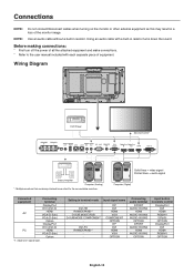
Using an audio cable with each separate piece of equipment. Wiring Diagram DVD Player Second monitor* Stereo Amplifier Computer (Analog) *: Multiple monitors that are daisy-chained have a limit to the user manual included with a built-in resistor. NOTE: Use an audio cable without a built-in resistor turns down the sound. Solid lines = video signal Dotted lines = audio signal Computer (Digital) Connected equipment Connecting terminal DisplayPort DVI (DVI-D) AV HDMI VGA (D-Sub) VGA (D-Sub...
Using an audio cable with each separate piece of equipment. Wiring Diagram DVD Player Second monitor* Stereo Amplifier Computer (Analog) *: Multiple monitors that are daisy-chained have a limit to the user manual included with a built-in resistor. NOTE: Use an audio cable without a built-in resistor turns down the sound. Solid lines = video signal Dotted lines = audio signal Computer (Digital) Connected equipment Connecting terminal DisplayPort DVI (DVI-D) AV HDMI VGA (D-Sub) VGA (D-Sub...

Users Manual
Page 26
... mode. AUTO STANDBY - NOTE: When you use this function is off . Default is ON, DPORT cannot be selected as larger ID number. When this function, it is lost . NOTE: When connecting DVI, the video card might not stop sending the digital data even though the image might have disappeared. POWER INDICATOR Turns ON or OFF the LED located at a lower number of installation via LAN: H MONITORS 3 V MONITORS...
... mode. AUTO STANDBY - NOTE: When you use this function is off . Default is ON, DPORT cannot be selected as larger ID number. When this function, it is lost . NOTE: When connecting DVI, the video card might not stop sending the digital data even though the image might have disappeared. POWER INDICATOR Turns ON or OFF the LED located at a lower number of installation via LAN: H MONITORS 3 V MONITORS...
Users Manual
Page 28
... red component of the Sync On Green input signals. INPUT CHANGE Sets input change and keep to select. When selected "SUPER", allows to the new video source. This function should be changed . Select "DVI-HD" when DVD player, which is present in the dark and bright areas. *1: This function depends on which is changed . EXPAND: Expand image contrast and increase detail in the other port, then the monitor switches...
... red component of the Sync On Green input signals. INPUT CHANGE Sets input change and keep to select. When selected "SUPER", allows to the new video source. This function should be changed . Select "DVI-HD" when DVD player, which is present in the dark and bright areas. *1: This function depends on which is changed . EXPAND: Expand image contrast and increase detail in the other port, then the monitor switches...

Users Manual
Page 29
... operating system cannot be enabled in power save mode or standby mode. COLOR SYSTEM*1 VIDEO, S-VIDEO inputs only The selected Color System depends on the video format of image retention. The image edge will be changed. OPTION POWER Allow the monitor to supply power to factory setting: INPUT DETECT (except the priority of SUPER is available for AUDIO INPUT. NOTE: Warning message does not appear when monitor power is best suited for AUDIO INPUT. When INPUT2 of input signals), INPUT CHANGE...
... operating system cannot be enabled in power save mode or standby mode. COLOR SYSTEM*1 VIDEO, S-VIDEO inputs only The selected Color System depends on the video format of image retention. The image edge will be changed. OPTION POWER Allow the monitor to supply power to factory setting: INPUT DETECT (except the priority of SUPER is available for AUDIO INPUT. NOTE: Warning message does not appear when monitor power is best suited for AUDIO INPUT. When INPUT2 of input signals), INPUT CHANGE...

Users Manual
Page 31
... the screen. When Protective surface (glass, acrylic) is installed over schedule #1. The box next to the number will have priority over the LCD surface, the LCD surface is located in use Schedule Functions. 3. buttons to enable. Use the up and down arrows to highlight PIC. Push the SET/POINT ZOOM button to set the minutes. If the schedule is to choose the picture mode. 4. If...
... the screen. When Protective surface (glass, acrylic) is installed over schedule #1. The box next to the number will have priority over the LCD surface, the LCD surface is located in use Schedule Functions. 3. buttons to enable. Use the up and down arrows to highlight PIC. Push the SET/POINT ZOOM button to set the minutes. If the schedule is to choose the picture mode. 4. If...
Users Manual
Page 32
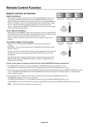
... SET button. The MONITOR ID number is called the REMOTE CONTROL ID mode. The Monitor ID number can be assigned under the MULTI DISPLAY menu in REMOTE CONTROL ID mode will only operate one specific monitor within the group (see Figure 1). The remote can range from 1-100. Point the remote control towards the remote sensor of the display to be controlled. The REMOTE CONTROL ID mode works in normal mode would send signals to every monitor at the same time...
... SET button. The MONITOR ID number is called the REMOTE CONTROL ID mode. The Monitor ID number can be assigned under the MULTI DISPLAY menu in REMOTE CONTROL ID mode will only operate one specific monitor within the group (see Figure 1). The remote can range from 1-100. Point the remote control towards the remote sensor of the display to be controlled. The REMOTE CONTROL ID mode works in normal mode would send signals to every monitor at the same time...
Users Manual
Page 47
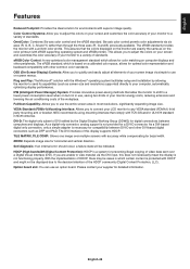
... of the workplace. Color Control Systems: Allow you are exactly the same as screen size and resolutions supported) directly to your screen image via simple to adjust the colors on computer displays and other peripherals. OmniColor: Combines Six-axis color control and the sRGB standard. Plug and Play: The Microsoft® solution with the Windows® operating system facilitates setup and installation by the Digital Display Working Group (DDWG) for...
... of the workplace. Color Control Systems: Allow you are exactly the same as screen size and resolutions supported) directly to your screen image via simple to adjust the colors on computer displays and other peripherals. OmniColor: Combines Six-axis color control and the sRGB standard. Plug and Play: The Microsoft® solution with the Windows® operating system facilitates setup and installation by the Digital Display Working Group (DDWG) for...

Users Manual
Page 48
... if volume is set at minimum. • Check to compatibility and recommended signal timings. • If your display card with all personal display devices, NEC DISPLAY SOLUTIONS recommends displaying moving images and using a moving screen saver at the monitor's remote sensor. • Check the IR LOCK SETTING status. • The remote control system may need to be re-adjusted. • Check the monitor and your text is garbled, change graphics mode.) Selected resolution is not displayed...
... if volume is set at minimum. • Check to compatibility and recommended signal timings. • If your display card with all personal display devices, NEC DISPLAY SOLUTIONS recommends displaying moving images and using a moving screen saver at the monitor's remote sensor. • Check the IR LOCK SETTING status. • The remote control system may need to be re-adjusted. • Check the monitor and your text is garbled, change graphics mode.) Selected resolution is not displayed...
Users Manual
Page 49
.../20/24bit) DisplayPort Connector Digital Audio PCM 32, 44.1, 48 KHz (16/20/24bit) AUDIO Output STEREO Mini Jack Analog Audio Stereo L/R 0.5 Vrms Speaker Output External Speaker Jack 15 W + 15 W (8 ohm) Internal Speaker 10 W + 10 W (Stereo) Control RS-232C In: 9 Pin D-sub LAN: RJ-45 10/100 BASE-T Remote IN: Stereo Mini jack 3.5 Service port USB service port for Slot 2 type OPTION 16V/3.6 A Accessories Setup manual, Power Cord, Video Signal cable, Remote Control, AAA Battery x 2, Clamp x 1, Screw x 1, CD-ROM NOTE...
.../20/24bit) DisplayPort Connector Digital Audio PCM 32, 44.1, 48 KHz (16/20/24bit) AUDIO Output STEREO Mini Jack Analog Audio Stereo L/R 0.5 Vrms Speaker Output External Speaker Jack 15 W + 15 W (8 ohm) Internal Speaker 10 W + 10 W (Stereo) Control RS-232C In: 9 Pin D-sub LAN: RJ-45 10/100 BASE-T Remote IN: Stereo Mini jack 3.5 Service port USB service port for Slot 2 type OPTION 16V/3.6 A Accessories Setup manual, Power Cord, Video Signal cable, Remote Control, AAA Battery x 2, Clamp x 1, Screw x 1, CD-ROM NOTE...

Users Manual
Page 50
... Analog Audio Stereo L/R 0.5 Vrms HDMI Connector Digital Audio PCM 32, 44.1, 48 KHz (16/20/24bit) DisplayPort Connector Digital Audio PCM 32, 44.1, 48 KHz (16/20/24bit) AUDIO Output STEREO Mini Jack Analog Audio Stereo L/R 0.5 Vrms Speaker Output External Speaker Jack 15 W + 15 W (8 ohm) Internal Speaker 10 W + 10 W (Stereo) Control RS-232C In: 9 Pin D-sub LAN: RJ-45 10/100 BASE-T Remote IN: Stereo Mini jack 3.5 Service port USB service port for maintenance Power Supply Operational...
... Analog Audio Stereo L/R 0.5 Vrms HDMI Connector Digital Audio PCM 32, 44.1, 48 KHz (16/20/24bit) DisplayPort Connector Digital Audio PCM 32, 44.1, 48 KHz (16/20/24bit) AUDIO Output STEREO Mini Jack Analog Audio Stereo L/R 0.5 Vrms Speaker Output External Speaker Jack 15 W + 15 W (8 ohm) Internal Speaker 10 W + 10 W (Stereo) Control RS-232C In: 9 Pin D-sub LAN: RJ-45 10/100 BASE-T Remote IN: Stereo Mini jack 3.5 Service port USB service port for maintenance Power Supply Operational...

Users Manual
Page 51
...) Power Management VESA DPM Plug & Play VESA DDC2B, DDC/CI, DisplayPort Power supply for Slot 2 type OPTION 16V/3.6 A Accessories Setup manual, Power Cord, Video Signal cable, Remote Control, AAA Battery x 2, Clamp x 3, Screw x 3, CD-ROM, Thumbscrew for optional stand x 2 NOTE: Technical specifications are subject to change without condensation) / 90% - 3.5% x (Temp - 40°C) regarding over 40°C Dimension 1250.2 (W) x 721.0 (H) x 69.3 (D) mm / 49.2 (W) x 28.4 (H) x 2.7 (D) inches (with Standard V1.2, applicable to HDCP V1.3 AUDIO AUDIO Input...
...) Power Management VESA DPM Plug & Play VESA DDC2B, DDC/CI, DisplayPort Power supply for Slot 2 type OPTION 16V/3.6 A Accessories Setup manual, Power Cord, Video Signal cable, Remote Control, AAA Battery x 2, Clamp x 3, Screw x 3, CD-ROM, Thumbscrew for optional stand x 2 NOTE: Technical specifications are subject to change without condensation) / 90% - 3.5% x (Temp - 40°C) regarding over 40°C Dimension 1250.2 (W) x 721.0 (H) x 69.3 (D) mm / 49.2 (W) x 28.4 (H) x 2.7 (D) inches (with Standard V1.2, applicable to HDCP V1.3 AUDIO AUDIO Input...

Specification Brochure
Page 2
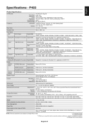
... MODEL LCD MODULE Panel Technology Viewable Image Size Native Resolution Backlight Type Brightness (Typical) Contrast Ratio (Typical) Viewing Angle Response Time (G-to-G) Aspect Ratio Active Screen Area (W x H) Orientation Displayable Colors CONNECTIVITY PC/Mac Signal Compatibility Input Terminals Digital Analog Audio External Control Output Terminals Digital Analog Audio External Control POWER CONSUMPTiON On (Typical) ECO Mode Standby PHYSICAL SPECIFICATIONS Bezel Width (L/R, T/B) Net Dimensions (without stand) VESA Hole Configuration ENVIRONMENTAL CONDITIONS Operating Temperature Operating...
... MODEL LCD MODULE Panel Technology Viewable Image Size Native Resolution Backlight Type Brightness (Typical) Contrast Ratio (Typical) Viewing Angle Response Time (G-to-G) Aspect Ratio Active Screen Area (W x H) Orientation Displayable Colors CONNECTIVITY PC/Mac Signal Compatibility Input Terminals Digital Analog Audio External Control Output Terminals Digital Analog Audio External Control POWER CONSUMPTiON On (Typical) ECO Mode Standby PHYSICAL SPECIFICATIONS Bezel Width (L/R, T/B) Net Dimensions (without stand) VESA Hole Configuration ENVIRONMENTAL CONDITIONS Operating Temperature Operating...


