Manual
Page 2
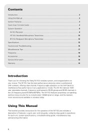
... each unit, system specifications, a troubleshooting guide, miscellaneous tips, and servicing information. 2 Using This Manual This booklet provides instructions for the operation of the W-1KU and includes a description of features, a quick user controls guide, a step‑by‑step guide to operations for choosing the Nady W-1KU wireless system, and congratulations on the UHF band for an industry-best 120dB dynamic range, and the clearest, most natural sound available in any...
... each unit, system specifications, a troubleshooting guide, miscellaneous tips, and servicing information. 2 Using This Manual This booklet provides instructions for the operation of the W-1KU and includes a description of features, a quick user controls guide, a step‑by‑step guide to operations for choosing the Nady W-1KU wireless system, and congratulations on the UHF band for an industry-best 120dB dynamic range, and the clearest, most natural sound available in any...
Manual
Page 3
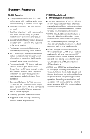
... easy frequency synchronization • Front panel backlit LCD display indicates selected audio output Volume level, Group, Channel, RF signal strength meter, A/B Diversity antenna status; transmitting High/Low RF power switch for longest reliable, economical battery life 3 Separate audio LED bar graph display provides instantaneous audio level status from a distance • Back panel Balanced XLR Mic level and Unbalanced 1⁄4" Line level audio output jacks, squelch control, RF BNC connectors for dual removable 1/2 wave antennas, and DC power input jack • Externally powered...
... easy frequency synchronization • Front panel backlit LCD display indicates selected audio output Volume level, Group, Channel, RF signal strength meter, A/B Diversity antenna status; transmitting High/Low RF power switch for longest reliable, economical battery life 3 Separate audio LED bar graph display provides instantaneous audio level status from a distance • Back panel Balanced XLR Mic level and Unbalanced 1⁄4" Line level audio output jacks, squelch control, RF BNC connectors for dual removable 1/2 wave antennas, and DC power input jack • Externally powered...

Manual
Page 4
...), Volume Levels (0-63), A-B Diversity, and RF signal strength indicator 1-6 bars 3. If the IR data download is on the LCD display. 12. LCD DISPLAY For indication of the Diversity antenna icons on 4. FREQUENCY CHANNEL Indicates selected frequency channel from 00-99 6. SYNC BUTTON Press to make the IR link download the receiver's selected frequency to the TX for linking the RX to the TX. SET To scroll LCD menu and set the selected program/function...
...), Volume Levels (0-63), A-B Diversity, and RF signal strength indicator 1-6 bars 3. If the IR data download is on the LCD display. 12. LCD DISPLAY For indication of the Diversity antenna icons on 4. FREQUENCY CHANNEL Indicates selected frequency channel from 00-99 6. SYNC BUTTON Press to make the IR link download the receiver's selected frequency to the TX for linking the RX to the TX. SET To scroll LCD menu and set the selected program/function...

Manual
Page 5
... AUDIO OUT Line level audio output-adjustable 18. SINGLE UNIT RACK MOUNT KIT (Optional) RMK-1KUS 21. DC POWER SUPPLY UNIT DC15VDC/400mA 15. BALANCED MIC OUT Audio output- turn CCW for maximum range; W-1KU Receiver: Back View 13 15 16 17 18 19 14 13. ANTENNA 1/2 wave antennas for A/B connectors Mounting Rackears for RF True Diversity reception 19. RF CONNECTORS A/B Antenna jacks for Receiver 20. DC INPUT JACK For connecting external...
... AUDIO OUT Line level audio output-adjustable 18. SINGLE UNIT RACK MOUNT KIT (Optional) RMK-1KUS 21. DC POWER SUPPLY UNIT DC15VDC/400mA 15. BALANCED MIC OUT Audio output- turn CCW for maximum range; W-1KU Receiver: Back View 13 15 16 17 18 19 14 13. ANTENNA 1/2 wave antennas for A/B connectors Mounting Rackears for RF True Diversity reception 19. RF CONNECTORS A/B Antenna jacks for Receiver 20. DC INPUT JACK For connecting external...

Manual
Page 6
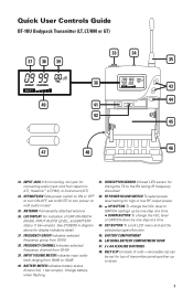
LCD DISPLAY For indication of GRP (00-09)/CH (00-99), INPUT AUDIO LEVEL, and BATTERY status (1 bar=empty). POWER HI/LOW RF power level setting for linking the TX to the RX during IR frequency download. 31. INTERNAL ANTENNA Built-In antenna 30. IR RECEPTOR SENSOR/WINDOW Infrared LED sensor for high or low RF output power 28. Quick User Controls Guide HT-1KU Handheld Transmitter 22 IR H RF L 23...
LCD DISPLAY For indication of GRP (00-09)/CH (00-99), INPUT AUDIO LEVEL, and BATTERY status (1 bar=empty). POWER HI/LOW RF power level setting for linking the TX to the RX during IR frequency download. 31. INTERNAL ANTENNA Built-In antenna 30. IR RECEPTOR SENSOR/WINDOW Infrared LED sensor for high or low RF output power 28. Quick User Controls Guide HT-1KU Handheld Transmitter 22 IR H RF L 23...
Manual
Page 7
... change the VOL level or GRP/CH down 7 SET BUTTON To scroll LCD menu and set to MUTE to the RX during IR frequency download 42. OFF/MUTE/ON Slide power switch to ON or OFF to -30dB 40. ANTENNA Permanently attached antenna 36. FREQUENCY CHANNEL Indicates selected frequency channel from 00-09 38. IR RECEPTOR SENSOR Infrared LED sensor for high or low RF output power 43. INPUT JACK 3.5mm locking mini jack...
... change the VOL level or GRP/CH down 7 SET BUTTON To scroll LCD menu and set to MUTE to the RX during IR frequency download 42. OFF/MUTE/ON Slide power switch to ON or OFF to -30dB 40. ANTENNA Permanently attached antenna 36. FREQUENCY CHANNEL Indicates selected frequency channel from 00-09 38. IR RECEPTOR SENSOR Infrared LED sensor for high or low RF output power 43. INPUT JACK 3.5mm locking mini jack...
Manual
Page 8
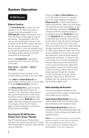
... the Set button. System Operation W-1KU Receiver Buttons Function The Power Button (12) is used to Exit Set Up Mode by pressing the Set Button (8). The backlight on the LCD will flash quickly. Press the (Up) or (Down) Buttons once or the Set button once prior to be desirable open channels. Choose the W-1KU operating frequency by -side with another W-1KU receiver. The IR Sync Button (11) is off. Press the IR Sync Button while the main menu is displayed...
... the Set button. System Operation W-1KU Receiver Buttons Function The Power Button (12) is used to Exit Set Up Mode by pressing the Set Button (8). The backlight on the LCD will flash quickly. Press the (Up) or (Down) Buttons once or the Set button once prior to be desirable open channels. Choose the W-1KU operating frequency by -side with another W-1KU receiver. The IR Sync Button (11) is off. Press the IR Sync Button while the main menu is displayed...
Manual
Page 9
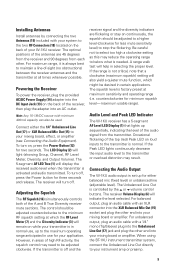
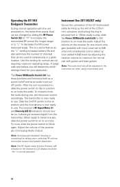
... Connecting the Audio Equipment). The receiver will turn off , press the Power button for your instrument amp or preamp. 9 However, in certain applications. Be careful not to select too high a clockwise setting as this may result. counterclockwise for two seconds. For unbalanced output, plug an audio cable with a 1⁄4" mono (Tip/Sleeve) plug into the DC Input Jack (13) on loud inputs to be used. Installing Antennas Install antennas by the or volume control buttons...
... Connecting the Audio Equipment). The receiver will turn off , press the Power button for your instrument amp or preamp. 9 However, in certain applications. Be careful not to select too high a clockwise setting as this may result. counterclockwise for two seconds. For unbalanced output, plug an audio cable with a 1⁄4" mono (Tip/Sleeve) plug into the DC Input Jack (13) on loud inputs to be used. Installing Antennas Install antennas by the or volume control buttons...
Manual
Page 10
... replaced after one second indicating IR data transfer, and then once more at the minimum level before plugging in use or as indicated to be programmed to -amp connection. To install the batteries onto the battery compartment, unscrew the Battery Compartment Cover (22) by holding the IR LED Receptor Sensor about 6"-12" from the receiver (see Selecting the W-1KU Receiver Volume Level/Group/Channel and Selecting...
... replaced after one second indicating IR data transfer, and then once more at the minimum level before plugging in use or as indicated to be programmed to -amp connection. To install the batteries onto the battery compartment, unscrew the Battery Compartment Cover (22) by holding the IR LED Receptor Sensor about 6"-12" from the receiver (see Selecting the W-1KU Receiver Volume Level/Group/Channel and Selecting...
Manual
Page 11
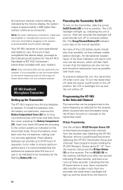
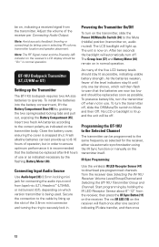
... menu. A range walk test before returning to select Hi/Low power transmission (see Operating the HT-1KU Handheld Transmitter). The default factory setting is set mode only. The or Buttons (25) work in a given location. This is preset at the next power on the receiver. Note: The IR link is best for loudest input). Use the or buttons to change the volume input level only, press the Set button three times to -30dB (for your application. HT-1KU Transmitter Switches At Power...
... menu. A range walk test before returning to select Hi/Low power transmission (see Operating the HT-1KU Handheld Transmitter). The default factory setting is set mode only. The or Buttons (25) work in a given location. This is preset at the next power on the receiver. Note: The IR link is best for loudest input). Use the or buttons to change the volume input level only, press the Set button three times to -30dB (for your application. HT-1KU Transmitter Switches At Power...
Manual
Page 12
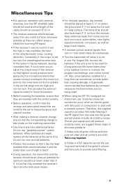
... light up. Adjust the volume of operation, but in order to operate. After ten seconds the backlight will flash once after one bar shows, which version transmitter is recommended that the batteries are now too low and should be "On" in use or as selected for connecting the audio input cord from the receiver (see Selecting the W-1KU Receiver Volume Level/Group/Channel and Selecting the BT-1KU Transmitter Group and Channel). Start programming...
... light up. Adjust the volume of operation, but in order to operate. After ten seconds the backlight will flash once after one bar shows, which version transmitter is recommended that the batteries are now too low and should be "On" in use or as selected for connecting the audio input cord from the receiver (see Selecting the W-1KU Receiver Volume Level/Group/Channel and Selecting the BT-1KU Transmitter Group and Channel). Start programming...
Manual
Page 13
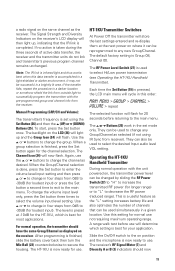
... is infrared light and thus works best when this order: MAIN MENU > GROUP > CHANNEL > VOLUME > repeat The selected function will transmit a radio signal on the same channel as displayed on where it latches. input level only, press the Set button three times to the main menu. When a group selection is preset at 0dB for GT and -10dB for 20 seconds before returning to select the volume input level setting. The level is finished, press the Set button again...
... is infrared light and thus works best when this order: MAIN MENU > GROUP > CHANNEL > VOLUME > repeat The selected function will transmit a radio signal on the same channel as displayed on where it latches. input level only, press the Set button three times to the main menu. When a group selection is preset at 0dB for GT and -10dB for 20 seconds before returning to select the volume input level setting. The level is finished, press the Set button again...
Manual
Page 14
... normal use with Input Level set the power switch accordingly. The transmitter is now ready to securely lock in. Slide the On/Off switch to the on position and the microphone is a useful feature as when using a hard-wired cord. Note: The audio level should be adjusted on the instrument as the "L" setting increases battery life and also optimizes the number of the receiver per Connecting Audio Output. Adjust the volume of channels that...
... normal use with Input Level set the power switch accordingly. The transmitter is now ready to securely lock in. Slide the On/Off switch to the on position and the microphone is a useful feature as when using a hard-wired cord. Note: The audio level should be adjusted on the instrument as the "L" setting increases battery life and also optimizes the number of the receiver per Connecting Audio Output. Adjust the volume of channels that...
Manual
Page 15
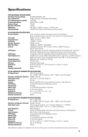
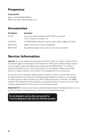
Synthesized (1000 channels switchable) 25kHz/step PLL system frequency stability Specifications SYSTEM OVERALL SPECIFICATIONS Operating Frequency Range 672MHz-697MHz (US) Freq.
Synthesized (1000 channels switchable) 25kHz/step PLL system frequency stability Specifications SYSTEM OVERALL SPECIFICATIONS Operating Frequency Range 672MHz-697MHz (US) Freq.
Manual
Page 16
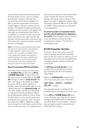
... Group/Channel Selected on , but more resistant to the Selected Channel Programming the HT-1KU/BT-1KU with previously tuned systems all setups. The above and below the selected channel for optimum interference-free operation (i.e. Please also note the pickup pattern characteristics of the mic. However, they pick up sound sources best that location. See: Selecting the W-1KU Receiver Volume Level / Group / Channel Selecting the HT-1KU/BT-1KU Transmitter Group and Channel Programming the HT-1KU/BT-1KU to...
... Group/Channel Selected on , but more resistant to the Selected Channel Programming the HT-1KU/BT-1KU with previously tuned systems all setups. The above and below the selected channel for optimum interference-free operation (i.e. Please also note the pickup pattern characteristics of the mic. However, they pick up sound sources best that location. See: Selecting the W-1KU Receiver Volume Level / Group / Channel Selecting the HT-1KU/BT-1KU Transmitter Group and Channel Programming the HT-1KU/BT-1KU to...
Manual
Page 17
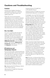
... antennas, low loss RF shielded cable should be used and the length of the cable should not exceed 10' (3 m). • The receiver antennas should be kept away from two or more transmitters simultaneously. • Turn the transmitter off . If such noise occurs, adjust the output level of the attached audio mixer, causing distortion. Keep antennas away from noise sources such as motors, automobiles, neon lights, signal...
... antennas, low loss RF shielded cable should be used and the length of the cable should not exceed 10' (3 m). • The receiver antennas should be kept away from two or more transmitters simultaneously. • Turn the transmitter off . If such noise occurs, adjust the output level of the attached audio mixer, causing distortion. Keep antennas away from noise sources such as motors, automobiles, neon lights, signal...
Manual
Page 18
.... Ship your unit prepaid to the Support page at (510) 652-2411 for a Return Authorization (R/A) Number and service quote (if out of a unit under warranty, please follow the instructions in your wireless system require service, please contact the Nady Service Department at www.nady.com for BT-1KU/GT transmitter, 3.5mm locking mini plug to service this product. Should your country through...
.... Ship your unit prepaid to the Support page at (510) 652-2411 for a Return Authorization (R/A) Number and service quote (if out of a unit under warranty, please follow the instructions in your wireless system require service, please contact the Nady Service Department at www.nady.com for BT-1KU/GT transmitter, 3.5mm locking mini plug to service this product. Should your country through...

Manual
Page 19
... typically connectors, cables, potentiometers, switches and similar components); Communication with the sale or use of this Nady Systems' product. Whereas some states do not return your warranty service directly. will perform all warranty service and return the unit to connect or operate the unit in... responsible, for a return authorization (RA) number. finish or appearance items; will provide a quote for repair. Any service not performed by Nady will automatically void this warranty and will repair or replace the unit free of charge, subject to the store where ...
... typically connectors, cables, potentiometers, switches and similar components); Communication with the sale or use of this Nady Systems' product. Whereas some states do not return your warranty service directly. will perform all warranty service and return the unit to connect or operate the unit in... responsible, for a return authorization (RA) number. finish or appearance items; will provide a quote for repair. Any service not performed by Nady will automatically void this warranty and will repair or replace the unit free of charge, subject to the store where ...


