FSM7226RS / FSM7250RS Hardware Installation Guide
Page 2
... trademarks or registered trademarks of their respective holders. Technical Support Please refer to the support information card that the NETGEAR ProSafe™ 48-Port L2+ Managed Stackable Switch with 2 Gigabit ports FSM7250RS has been suppressed in accordance with the conditions set out in accordance with faster expert technical support and timely notices of some equipment (for example, test transmitters) in the BMPT-AmtsblVfg 243/1991 and...
... trademarks or registered trademarks of their respective holders. Technical Support Please refer to the support information card that the NETGEAR ProSafe™ 48-Port L2+ Managed Stackable Switch with 2 Gigabit ports FSM7250RS has been suppressed in accordance with the conditions set out in accordance with faster expert technical support and timely notices of some equipment (for example, test transmitters) in the BMPT-AmtsblVfg 243/1991 and...
FSM7226RS / FSM7250RS Hardware Installation Guide
Page 3
... following two conditions: • This device not cause harmful interference. • This device must accept any interference received, including interference that the NETGEAR ProSafe™ 48-Port L2+ Managed Stackable Switch with 2 Gigabit ports FSM7250RS is connected. • Consult the dealer or an experienced radio/TV technician for radio-noise emissions from digital apparatus as set out in accordance with the...
... following two conditions: • This device not cause harmful interference. • This device must accept any interference received, including interference that the NETGEAR ProSafe™ 48-Port L2+ Managed Stackable Switch with 2 Gigabit ports FSM7250RS is connected. • Consult the dealer or an experienced radio/TV technician for radio-noise emissions from digital apparatus as set out in accordance with the...

FSM7226RS / FSM7250RS Hardware Installation Guide
Page 4
... Support Refer to certify that the NETGEAR ProSafe™ 48-Port L2+ Managed Stackable Switch with 2 Gigabit ports FSM7250RS. Conformity is declared by the application of EN 55 022 Class A (CISPR 22) and EN 55 024. A direct connection to take appropriate measures. Warning: This is shielded against the generation of radio interference in which case the user be required to the Internet...
... Support Refer to certify that the NETGEAR ProSafe™ 48-Port L2+ Managed Stackable Switch with 2 Gigabit ports FSM7250RS. Conformity is declared by the application of EN 55 022 Class A (CISPR 22) and EN 55 024. A direct connection to take appropriate measures. Warning: This is shielded against the generation of radio interference in which case the user be required to the Internet...
FSM7226RS / FSM7250RS Hardware Installation Guide
Page 7
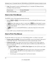
... scope of this manual is used to install, configure and troubleshoot the managed switches. This manual uses the following formats to highlight special messages: Note: This format is intended for readers with intermediate computer and Internet skills. The information in the following typographical conventions: Italic italic Emphasis, books, CDs, file and server names, extensions URL links • Formats. Note: Product updates are described in...
... scope of this manual is used to install, configure and troubleshoot the managed switches. This manual uses the following formats to highlight special messages: Note: This format is intended for readers with intermediate computer and Internet skills. The information in the following typographical conventions: Italic italic Emphasis, books, CDs, file and server names, extensions URL links • Formats. Note: Product updates are described in...
FSM7226RS / FSM7250RS Hardware Installation Guide
Page 8
... the free Adobe Acrobat reader installed in the upper left corner of any page. • Click the PDF of This Chapter link at the top left of contents and a button that displays an index. Select File > Print from the browser menu to access the full NETGEAR, Inc. Printing a PDF chapter. The PDF version of the chapter you were viewing opens in a browser window. •...
... the free Adobe Acrobat reader installed in the upper left corner of any page. • Click the PDF of This Chapter link at the top left of contents and a button that displays an index. Select File > Print from the browser menu to access the full NETGEAR, Inc. Printing a PDF chapter. The PDF version of the chapter you were viewing opens in a browser window. •...
FSM7226RS / FSM7250RS Hardware Installation Guide
Page 11
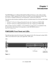
...-compliant network solution. LEDs Reset button Figure 1-1 RJ-45 jacks Copper/fiber combo ports 1-1 v1.0, October 2008 It includes powerful management features that you can be free-standing, or rack-mounted in a wiring closet or an equipment room. Chapter 1 Introduction The NETGEAR Layer 2+ Managed Stackable Fast Ethernet Switch is a state-of the managed switch. FSM7226RS Front Panel and LEDs The following NETGEAR switches: • ProSafe™ 24-Port L2+ Managed Stackable Switch with 2 Gigabit ports FSM7226RS...
...-compliant network solution. LEDs Reset button Figure 1-1 RJ-45 jacks Copper/fiber combo ports 1-1 v1.0, October 2008 It includes powerful management features that you can be free-standing, or rack-mounted in a wiring closet or an equipment room. Chapter 1 Introduction The NETGEAR Layer 2+ Managed Stackable Fast Ethernet Switch is a state-of the managed switch. FSM7226RS Front Panel and LEDs The following NETGEAR switches: • ProSafe™ 24-Port L2+ Managed Stackable Switch with 2 Gigabit ports FSM7226RS...
FSM7226RS / FSM7250RS Hardware Installation Guide
Page 13
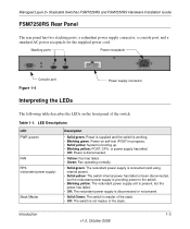
... FSM7250RS Hardware Installation Guide FSM7250RS Rear Panel The rear panel has two stacking ports, a redundant power supply connector, a console port, and a standard AC power receptacle for the supplied power cord. Stacking ports Power receptacle Console port Figure 1-4 Interpreting the LEDs Power supply connector The following table describes the LEDs on self-test (POST) in progress. • Solid yellow: System is booting up. • Blinking yellow: POST, CPU, or power supply has failed. • Off: Power is disconnected. • Yellow: Fan has failed. • Green: Fan...
... FSM7250RS Hardware Installation Guide FSM7250RS Rear Panel The rear panel has two stacking ports, a redundant power supply connector, a console port, and a standard AC power receptacle for the supplied power cord. Stacking ports Power receptacle Console port Figure 1-4 Interpreting the LEDs Power supply connector The following table describes the LEDs on self-test (POST) in progress. • Solid yellow: System is booting up. • Blinking yellow: POST, CPU, or power supply has failed. • Off: Power is disconnected. • Yellow: Fan has failed. • Green: Fan...
FSM7226RS / FSM7250RS Hardware Installation Guide
Page 14
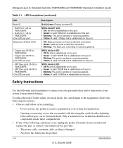
... Instructions Use the following safety guidelines to ensure your system documentation. - Opening or removing covers that are marked with the triangular symbol with a lightning bolt could expose you to electrical shock. An object has fallen into the product. 1-4 Introduction v1.0, October 2008 Managed Layer 2+ Stackable Switches FSM7226RS and FSM7250RS Hardware Installation Guide Table 1-1. SPD/Link/Act LED • Off:No link is established on the port...
... Instructions Use the following safety guidelines to ensure your system documentation. - Opening or removing covers that are marked with the triangular symbol with a lightning bolt could expose you to electrical shock. An object has fallen into the product. 1-4 Introduction v1.0, October 2008 Managed Layer 2+ Stackable Switches FSM7226RS and FSM7250RS Hardware Installation Guide Table 1-1. SPD/Link/Act LED • Off:No link is established on the port...

FSM7226RS / FSM7250RS Hardware Installation Guide
Page 17
...Hardware Installation Guide • Warranty and Support Card • ProSafe NMS100 Network Management System 30-day trial CD-ROM 2-1 v1.0, October 2008 Documentation including the Command Line Interface Reference for the ProSafe 7200RS Series Layer-2 Stackable Switches, the NETGEAR 7000 Series Managed Switch Administration Guide, the NETGEAR Installation Guide for the Managed Stackable Layer 2+ Fast Ethernet Switch models FSM7226RS and FSM7250RS. The package contains the following items: • Managed Stackable Layer 2+ Fast Ethernet Switch with preinstalled software • Power adapter...
...Hardware Installation Guide • Warranty and Support Card • ProSafe NMS100 Network Management System 30-day trial CD-ROM 2-1 v1.0, October 2008 Documentation including the Command Line Interface Reference for the ProSafe 7200RS Series Layer-2 Stackable Switches, the NETGEAR 7000 Series Managed Switch Administration Guide, the NETGEAR Installation Guide for the Managed Stackable Layer 2+ Fast Ethernet Switch models FSM7226RS and FSM7250RS. The package contains the following items: • Managed Stackable Layer 2+ Fast Ethernet Switch with preinstalled software • Power adapter...
FSM7226RS / FSM7250RS Hardware Installation Guide
Page 19
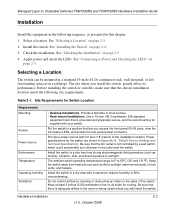
... switch. Table 2-1. See "Connecting to 55ºC (32º and 131ºF). The ambient switch operating temperature range is grounded and physically secure, and the rack-mounting kit supplied with a maximum relative humidity of 90%, noncondensing. Power specifications for Switch Location Requirements Mounting Access Power source Environment Temperature Operating humidity Ventilation • Desktop Installations. Keep the switch away from strong electromagnetic field generators (such as presented in Appendix A, "Default Factory Settings...
... switch. Table 2-1. See "Connecting to 55ºC (32º and 131ºF). The ambient switch operating temperature range is grounded and physically secure, and the rack-mounting kit supplied with a maximum relative humidity of 90%, noncondensing. Power specifications for Switch Location Requirements Mounting Access Power source Environment Temperature Operating humidity Ventilation • Desktop Installations. Keep the switch away from strong electromagnetic field generators (such as presented in Appendix A, "Default Factory Settings...

FSM7226RS / FSM7250RS Hardware Installation Guide
Page 21
... the rack. 5. Check cable routing to apply AC power: 1. Before you select an appropriate outlet, follow these steps to ensure that is mounted properly and securely. Check the Power LED on self-test (POST). • If the switch passes the test, the LED turns green. If the Power LED does not light up in the rack. Hardware Installation 2-5 v1.0, October 2008 Managed Layer 2+ Stackable Switches FSM7226RS and FSM7250RS Hardware Installation Guide 3. Verify that the power source is to the switch). Connect...
... the rack. 5. Check cable routing to apply AC power: 1. Before you select an appropriate outlet, follow these steps to ensure that is mounted properly and securely. Check the Power LED on self-test (POST). • If the switch passes the test, the LED turns green. If the Power LED does not light up in the rack. Hardware Installation 2-5 v1.0, October 2008 Managed Layer 2+ Stackable Switches FSM7226RS and FSM7250RS Hardware Installation Guide 3. Verify that the power source is to the switch). Connect...
FSM7226RS / FSM7250RS Hardware Installation Guide
Page 23
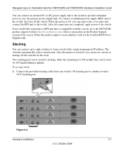
... Switches FSM7226RS and FSM7250RS Hardware Installation Guide You can connect an external DC-to-DC power supply unit to the switch to form a stack with this switch, go to the NETGEAR product support website http://www.kbserver.com. When the product support screen displays, look for 10-Gigabit Ethernet uplinks. Once the master is selected, you can be used for the Certified RPS Power Supplier link. To set up...
... Switches FSM7226RS and FSM7250RS Hardware Installation Guide You can connect an external DC-to-DC power supply unit to the switch to form a stack with this switch, go to the NETGEAR product support website http://www.kbserver.com. When the product support screen displays, look for 10-Gigabit Ethernet uplinks. Once the master is selected, you can be used for the Certified RPS Power Supplier link. To set up...

FSM7226RS / FSM7250RS Hardware Installation Guide
Page 24
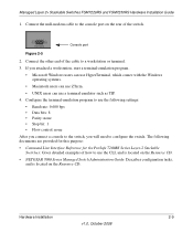
Connecting Equipment to the Switch You can use the Command Line Interface (CLI) to it with the product). Connecting a Console to the Switch After you install the switch and apply power, you can connect to identify the IP address. You can connect devices, a Gigabit Ethernet module, and/or a console to the master switch. Finally, connect the last switch in the stack. 4. To use a serial cable to connect the console to the switch. This single console connection lets you are stacking switches, see the Command Line Interface Reference for...
Connecting Equipment to the Switch You can use the Command Line Interface (CLI) to it with the product). Connecting a Console to the Switch After you install the switch and apply power, you can connect to identify the IP address. You can connect devices, a Gigabit Ethernet module, and/or a console to the master switch. Finally, connect the last switch in the stack. 4. To use a serial cable to connect the console to the switch. This single console connection lets you are stacking switches, see the Command Line Interface Reference for...
FSM7226RS / FSM7250RS Hardware Installation Guide
Page 25
... use HyperTerminal, which comes with the Windows operating systems. • Macintosh users can use ZTerm. • UNIX users can use the following documents are provided for this purpose: • Command Line Interface Reference for the ProSafe 7200RS Series Layer-2 Stackable Switches: Gives detailed examples of the cable to the console port on the Resource CD. Console port Figure 2-5 2. Connect the other end of how to configure the switch. Managed Layer 2+ Stackable Switches FSM7226RS and FSM7250RS Hardware Installation Guide...
... use HyperTerminal, which comes with the Windows operating systems. • Macintosh users can use ZTerm. • UNIX users can use the following documents are provided for this purpose: • Command Line Interface Reference for the ProSafe 7200RS Series Layer-2 Stackable Switches: Gives detailed examples of the cable to the console port on the Resource CD. Console port Figure 2-5 2. Connect the other end of how to configure the switch. Managed Layer 2+ Stackable Switches FSM7226RS and FSM7250RS Hardware Installation Guide...
FSM7226RS / FSM7250RS Hardware Installation Guide
Page 27
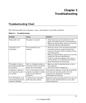
... attached device is disabled Break the loop by testing it in the required ports. network is set to any other networked device. 3-1 v1.0, October 2008 Link LED is properly inserted and locked into the port at the switch and the connected device. • Make sure that all connectors are securely positioned in an alternate environment where all cables used are functioning. File transfer is a problem. Port connection is not working. • Check the...
... attached device is disabled Break the loop by testing it in the required ports. network is set to any other networked device. 3-1 v1.0, October 2008 Link LED is properly inserted and locked into the port at the switch and the connected device. • Make sure that all connectors are securely positioned in an alternate environment where all cables used are functioning. File transfer is a problem. Port connection is not working. • Check the...
FSM7226RS / FSM7250RS Hardware Installation Guide
Page 28
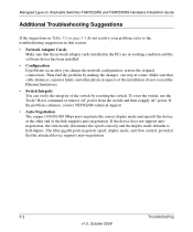
... problems occur after you change the network configuration, restore the original connections. Make sure that cable distances, repeater limits, and other end of the installation do not resolve your problem, refer to half-duplex. If the device does not support autonegotiation, the switch only determines the speed correctly and the duplex mode defaults to the troubleshooting suggestions in this section. • Network Adapter Cards Make sure that the attached device supports auto-negotiation. 3-2 Troubleshooting...
... problems occur after you change the network configuration, restore the original connections. Make sure that cable distances, repeater limits, and other end of the installation do not resolve your problem, refer to half-duplex. If the device does not support autonegotiation, the switch only determines the speed correctly and the duplex mode defaults to the troubleshooting suggestions in this section. • Network Adapter Cards Make sure that the attached device supports auto-negotiation. 3-2 Troubleshooting...
FSM7226RS / FSM7250RS Hardware Installation Guide
Page 29
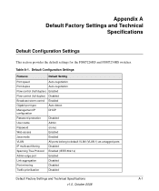
Default Configuration Settings Features Default Setting Port speed Auto-negotiation Port duplex Auto-negotiation Flow control (half duplex) Enabled Flow control (full duplex) Disabled Broadcast storm control Enabled Gigabit port type Auto detect Management IP configuration DHCP Password protection Disabled User name Admin Password (none) Web access Enabled Java mode Enabled VLAN All ports belong to default VLAN (VLAN 1) as untagged ports IP multicast filtering Disabled Spanning Tree Protocol Enabled (IEEE 802.1s) Admin edge port Enabled Link aggregation Disabled...
Default Configuration Settings Features Default Setting Port speed Auto-negotiation Port duplex Auto-negotiation Flow control (half duplex) Enabled Flow control (full duplex) Disabled Broadcast storm control Enabled Gigabit port type Auto detect Management IP configuration DHCP Password protection Disabled User name Admin Password (none) Web access Enabled Java mode Enabled VLAN All ports belong to default VLAN (VLAN 1) as untagged ports IP multicast filtering Disabled Spanning Tree Protocol Enabled (IEEE 802.1s) Admin edge port Enabled Link aggregation Disabled...
FSM7226RS / FSM7250RS Hardware Installation Guide
Page 30
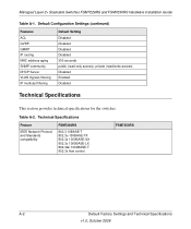
...GMRP IP routing MAC address aging SNMP community DHCP Server VLAN Ingress filtering IP multicast filtering Default Setting Disabled Disabled Disabled Disabled 300 seconds public (read-only access), private (read/write access) Disabled Enabled Disabled Technical Specifications This section provides technical specifications for the switches. Table A-2. Technical Specifications Feature IEEE Network Protocol and Standards compatibility FSM7226RS 802.3 10BASE-T 802.3u 100BASE-TX 802.3z 1000BASE-SX 802.3z 1000BASE-LX 802.3ab 1000BASE-T 802.3x flow control FSM7250RS A-2 Default Factory...
...GMRP IP routing MAC address aging SNMP community DHCP Server VLAN Ingress filtering IP multicast filtering Default Setting Disabled Disabled Disabled Disabled 300 seconds public (read-only access), private (read/write access) Disabled Enabled Disabled Technical Specifications This section provides technical specifications for the switches. Table A-2. Technical Specifications Feature IEEE Network Protocol and Standards compatibility FSM7226RS 802.3 10BASE-T 802.3u 100BASE-TX 802.3z 1000BASE-SX 802.3z 1000BASE-LX 802.3ab 1000BASE-T 802.3x flow control FSM7250RS A-2 Default Factory...
FSM7226RS / FSM7250RS Hardware Installation Guide
Page 31
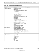
...; RFC1643 Ethernet Interface MIB • RFC1493 bridge MIB • RFC2131 DHCP client (and BootP) • RFC2138 RADIUS client • Broadcast storm control • Telnet sessions for management CPU (5) • Ping support • ARP support • Private enterprise MIB • Configuration file upload, download (TFTP) • Runtime image download (TFTP) • Command Line Interface • Web-based graphic user interface • Simple Network Time Protocol (SNTP) • Syslog • SSLv3/TLSv1.0 Web security • Secured Shell (SSHv1, v2) • 802.1Q Static VLAN...
...; RFC1643 Ethernet Interface MIB • RFC1493 bridge MIB • RFC2131 DHCP client (and BootP) • RFC2138 RADIUS client • Broadcast storm control • Telnet sessions for management CPU (5) • Ping support • ARP support • Private enterprise MIB • Configuration file upload, download (TFTP) • Runtime image download (TFTP) • Command Line Interface • Web-based graphic user interface • Simple Network Time Protocol (SNTP) • Syslog • SSLv3/TLSv1.0 Web security • Secured Shell (SSHv1, v2) • 802.1Q Static VLAN...
FSM7226RS / FSM7250RS Hardware Installation Guide
Page 32
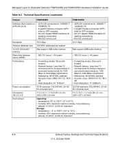
Managed Layer 2+ Stackable Switches FSM7226RS and FSM7250RS Hardware Installation Guide Table A-2. Power consumption 15 W maximum 100-240VAC, 50-60 32.8 W ...SFP) slots for SFP modules • two 2.5-Gigabit HDMI interfaces for stacking connectivity • RS-232 console port Bandwidth 18.8 Gbps 23.6 Gbps Address database size 16K MAC addresses per system 10/100/1000 buffer memory Max support 1MB buffer memory Max support 2MB buffer memory Mean time between failure (MTBF) • 562,110 hours (~ 64 years) • 385,102 hours (~ 44 years) Performance • Forwarding modes...
Managed Layer 2+ Stackable Switches FSM7226RS and FSM7250RS Hardware Installation Guide Table A-2. Power consumption 15 W maximum 100-240VAC, 50-60 32.8 W ...SFP) slots for SFP modules • two 2.5-Gigabit HDMI interfaces for stacking connectivity • RS-232 console port Bandwidth 18.8 Gbps 23.6 Gbps Address database size 16K MAC addresses per system 10/100/1000 buffer memory Max support 1MB buffer memory Max support 2MB buffer memory Mean time between failure (MTBF) • 562,110 hours (~ 64 years) • 385,102 hours (~ 44 years) Performance • Forwarding modes...


