
GSM7352S Hardware manual
Page 2
... to Publication Version 1.0, March 2006 Voluntary Control Council for compliance with part 15 of Microsoft Corporation in a residential installation. Note: This equipment has been tested and found to comply with the instructions, may be subject to part 15 of Netgear, Inc. All rights reserved. Trademarks The Netgear Logo, the Gear Guy, Everybody's connecting, and ProSafe are designed to test the series for...
... to Publication Version 1.0, March 2006 Voluntary Control Council for compliance with part 15 of Microsoft Corporation in a residential installation. Note: This equipment has been tested and found to comply with the instructions, may be subject to part 15 of Netgear, Inc. All rights reserved. Trademarks The Netgear Logo, the Gear Guy, Everybody's connecting, and ProSafe are designed to test the series for...

GSM7352S Hardware manual
Page 4
... Part Number: Publication Version Number GSM7328S and GSM7352S March 2006 managed switch • ProSafe 24-Port 10/100/1000 L3 managed Stackable Switch with 4 High-speed I/O Module Bays GSM7328S • ProSafe 48-Port 10/100/1000 L3 managed Stackable Switch with your Managed Stackable Layer 3 Fast Ethernet Switch. Conformity is a Class A product. Customer Support Refer to the Support Information Card that you can access at the universal resource locator (URL) http://www.netgear.com...
... Part Number: Publication Version Number GSM7328S and GSM7352S March 2006 managed switch • ProSafe 24-Port 10/100/1000 L3 managed Stackable Switch with 4 High-speed I/O Module Bays GSM7328S • ProSafe 48-Port 10/100/1000 L3 managed Stackable Switch with your Managed Stackable Layer 3 Fast Ethernet Switch. Conformity is a Class A product. Customer Support Refer to the Support Information Card that you can access at the universal resource locator (URL) http://www.netgear.com...

GSM7352S Hardware manual
Page 5
... 2-4 GSM7352S Front Panel and LEDs 2-4 GSM7352S Rear Panel 2-6 Safety Instructions ...2-7 Chapter 3 Hardware Installation Package Contents ...3-1 Protecting Against Electrostatic Discharge 3-2 Unpacking the Hardware 3-2 Installation ...3-3 Select a Location ...3-4 Install the Switch ...3-5 Check the Installation 3-6 Connect to Power and Check the LEDs 3-6 High-Speed I/O Module Bays 3-7 SPF Modules ...3-7 Stacking ...3-9 Connecting a Redundant Power Supply 3-10 Connecting Equipment to the Switch 3-10 RJ-45 Ports ...3-10 Connecting a Console to the Switch 3-11 i Publication Version...
... 2-4 GSM7352S Front Panel and LEDs 2-4 GSM7352S Rear Panel 2-6 Safety Instructions ...2-7 Chapter 3 Hardware Installation Package Contents ...3-1 Protecting Against Electrostatic Discharge 3-2 Unpacking the Hardware 3-2 Installation ...3-3 Select a Location ...3-4 Install the Switch ...3-5 Check the Installation 3-6 Connect to Power and Check the LEDs 3-6 High-Speed I/O Module Bays 3-7 SPF Modules ...3-7 Stacking ...3-9 Connecting a Redundant Power Supply 3-10 Connecting Equipment to the Switch 3-10 RJ-45 Ports ...3-10 Connecting a Console to the Switch 3-11 i Publication Version...

GSM7352S Hardware manual
Page 7
... highlight a procedure that will save time or resources. Warning: Ignoring this guide is used to the equipment. 1-1 v1.0, March 2006 Chapter 1 About This Manual The Managed Stackable Layer 3 Switches GSM7328S and GSM7352S Hardware Installation Guide describes installation and basic troubleshoting for network managers familiar with network management concepts and terminology. Audience, Conventions, Formats, and Scope This information in this type of note may result in a malfunction...
... highlight a procedure that will save time or resources. Warning: Ignoring this guide is used to the equipment. 1-1 v1.0, March 2006 Chapter 1 About This Manual The Managed Stackable Layer 3 Switches GSM7328S and GSM7352S Hardware Installation Guide describes installation and basic troubleshoting for network managers familiar with network management concepts and terminology. Audience, Conventions, Formats, and Scope This information in this type of note may result in a malfunction...

GSM7352S Hardware manual
Page 9
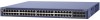
This guide describes hardware installation and basic troubleshooting for each product, see the NETGEAR Web site at http://www.netgear.com. speed Module Bays GSM7352S These switches can use to eliminate bottlenecks, boost performance, and increase productivity. It includes powerful management features that you can be free-standing, or rack-mounted in a wiring closet or an equipment room. For information about features for the following figure shows the...
This guide describes hardware installation and basic troubleshooting for each product, see the NETGEAR Web site at http://www.netgear.com. speed Module Bays GSM7352S These switches can use to eliminate bottlenecks, boost performance, and increase productivity. It includes powerful management features that you can be free-standing, or rack-mounted in a wiring closet or an equipment room. For information about features for the following figure shows the...

GSM7352S Hardware manual
Page 10
... switch. Table 2-1. RPS (redundant power supply) • Solid green: The redundant power supply is connected (and using internal power). • Solid yellow: The switch internal power has failed or been disconnected, but the power has failed. • Off: The redundant power supply is disconnected or not present. Managed Stackable Layer 3 Switches GSM7328S and GSM7352S Hardware Installation Guide The module bays support any combination of either the ProSafe 24-Gigabit Stackable Module (AX742) or the ProSafe 10-Gigabit Ethernet XFP Adapter...
... switch. Table 2-1. RPS (redundant power supply) • Solid green: The redundant power supply is connected (and using internal power). • Solid yellow: The switch internal power has failed or been disconnected, but the power has failed. • Off: The redundant power supply is disconnected or not present. Managed Stackable Layer 3 Switches GSM7328S and GSM7352S Hardware Installation Guide The module bays support any combination of either the ProSafe 24-Gigabit Stackable Module (AX742) or the ProSafe 10-Gigabit Ethernet XFP Adapter...

GSM7352S Hardware manual
Page 13
Managed Stackable Layer 3 Switches GSM7328S and GSM7352S Hardware Installation Guide The table below describes the GSM7352S LEDs on the front of GSM7300S switches. Fan • Red: Fan has failed • Off: Fan operating normally PWR (Power) • Solid green: Power is supplied and the switch is working. • Solid yellow: Power on Self Test (POST) in a stack of the switch. Master • Green: The switch is a master unit in a stack of GSM7300S series switches. • Off: The switch acts...
Managed Stackable Layer 3 Switches GSM7328S and GSM7352S Hardware Installation Guide The table below describes the GSM7352S LEDs on the front of GSM7300S switches. Fan • Red: Fan has failed • Off: Fan operating normally PWR (Power) • Solid green: Power is supplied and the switch is working. • Solid yellow: Power on Self Test (POST) in a stack of the switch. Master • Green: The switch is a master unit in a stack of GSM7300S series switches. • Off: The switch acts...

GSM7352S Hardware manual
Page 14
... Redundant power supply connector Console v1.0, March 2006 Introduction See "High-Speed I /O Modules (1 LED per module) SFP ports Description XFP Module present or Stacking Adapter present and ACT LED XFP Module present LED /ACT • Off: The 10GbE Adapter is not present. • Solid green: The 10GbE Adapter is present. • Blinking green: Packets transmission or reception is occurring on the port. • Blinking green: The port is changed to copper, the SFP LEDs change to OFF status. Managed...
... Redundant power supply connector Console v1.0, March 2006 Introduction See "High-Speed I /O Modules (1 LED per module) SFP ports Description XFP Module present or Stacking Adapter present and ACT LED XFP Module present LED /ACT • Off: The 10GbE Adapter is not present. • Solid green: The 10GbE Adapter is present. • Blinking green: Packets transmission or reception is occurring on the port. • Blinking green: The port is changed to copper, the SFP LEDs change to OFF status. Managed...

GSM7352S Hardware manual
Page 17
... software - Documentation including the Command Line Interface Reference for the ProSafe 7300S Series Layer-3 Stackable Switches, the Administration Manual for the SFP sockets • Rack-mounting kit • Null-modem serial cable (RS-232) with preinstalled software • Power adapter cord • Rubber footpads for tabletop installation • Rubber caps for the ProSafe 7300S Series Layer-3 Stackable Switches, the Quick Install Guide, and this Hardware Installation Guide • Warranty and Support Card • Quick Install Guide • ProSafe NMS100 Network Management...
... software - Documentation including the Command Line Interface Reference for the ProSafe 7300S Series Layer-3 Stackable Switches, the Administration Manual for the SFP sockets • Rack-mounting kit • Null-modem serial cable (RS-232) with preinstalled software • Power adapter cord • Rubber footpads for tabletop installation • Rubber caps for the ProSafe 7300S Series Layer-3 Stackable Switches, the Quick Install Guide, and this Hardware Installation Guide • Warranty and Support Card • Quick Install Guide • ProSafe NMS100 Network Management...

GSM7352S Hardware manual
Page 20
... rack-mount kit supplied with a maximum relative humidity of the switch. Be sure that is 0º to 55ºC (32º and 131ºF). The ambient switch operating temperature range is grounded and physically secure. Keep at least 2 inches (5.08 centimeters) free on a tabletop). Site Requirements for Switch Location Requirements Mounting Access Power source Environment Temperature Operating humidity Ventilation Cabling • Desktop Installations: Provide a flat table...
... rack-mount kit supplied with a maximum relative humidity of the switch. Be sure that is 0º to 55ºC (32º and 131ºF). The ambient switch operating temperature range is grounded and physically secure. Keep at least 2 inches (5.08 centimeters) free on a tabletop). Site Requirements for Switch Location Requirements Mounting Access Power source Environment Temperature Operating humidity Ventilation Cabling • Desktop Installations: Provide a flat table...

GSM7352S Hardware manual
Page 22
... Power and Check the LEDs The switch does not have an ON/OFF switch. Check cable routing to the switch). Verify that is mounted properly and securely. Before you apply power, perform the following sequence: • The LED turns yellow as the switch runs a Power-On Self-Test (POST). • If the switch passes the test, the LED turns green. Managed Stackable Layer 3 Switches GSM7328S and GSM7352S Hardware Installation Guide 4. Align the bracket and rack holes. Check the Installation Before you connect...
... Power and Check the LEDs The switch does not have an ON/OFF switch. Check cable routing to the switch). Verify that is mounted properly and securely. Before you apply power, perform the following sequence: • The LED turns yellow as the switch runs a Power-On Self-Test (POST). • If the switch passes the test, the LED turns green. Managed Stackable Layer 3 Switches GSM7328S and GSM7352S Hardware Installation Guide 4. Align the bracket and rack holes. Check the Installation Before you connect...

GSM7352S Hardware manual
Page 25
.... For information about working with the CLI, see the Command Line Interface Reference for the ProSafe 7300S Series Layer-3 Stackable Switches on the NETGEAR CD that shipped with a single management IP address. This single console connection lets you can use a serial cable to connect the console to the next in the stack. Connect the provided stacking cable between a pair of the stack. Managed Stackable Layer 3 Switches GSM7328S and GSM7352S Hardware Installation Guide Stacking You can be...
.... For information about working with the CLI, see the Command Line Interface Reference for the ProSafe 7300S Series Layer-3 Stackable Switches on the NETGEAR CD that shipped with a single management IP address. This single console connection lets you can use a serial cable to connect the console to the next in the stack. Connect the provided stacking cable between a pair of the stack. Managed Stackable Layer 3 Switches GSM7328S and GSM7352S Hardware Installation Guide Stacking You can be...

GSM7352S Hardware manual
Page 27
... connect a console to the switch: 1. Connect the null-modem cable to the console port on the rear of the cable to a workstation or terminal. 3. You can use a terminal emulator such as TIP. 4. Configure the terminal-emulation program to use the Command Line Interface (CLI) to identify the IP address. To use a console you attached a workstation, start a terminal-emulation program. • Microsoft Windows users can use the following items: • VT100/ANSI terminal, or a Windows...
... connect a console to the switch: 1. Connect the null-modem cable to the console port on the rear of the cable to a workstation or terminal. 3. You can use a terminal emulator such as TIP. 4. Configure the terminal-emulation program to use the Command Line Interface (CLI) to identify the IP address. To use a console you attached a workstation, start a terminal-emulation program. • Microsoft Windows users can use the following items: • VT100/ANSI terminal, or a Windows...

GSM7352S Hardware manual
Page 28
...-3 Stackable Switches: Gives detailed examples of how to configure the switch. Managed Stackable Layer 3 Switches GSM7328S and GSM7352S Hardware Installation Guide After you connect a console to the switch, you will need to use the CLI, and is located on the NETGEAR CD. • Administration Manual for the ProSafe 7300S Series Layer-3 Stackable Switches: Describes configuration tasks, and is located on the NETGEAR CD). • Command Line Interface Reference for this purpose: • Quick Install Guide: Explains basic setup and configuration...
...-3 Stackable Switches: Gives detailed examples of how to configure the switch. Managed Stackable Layer 3 Switches GSM7328S and GSM7352S Hardware Installation Guide After you connect a console to the switch, you will need to use the CLI, and is located on the NETGEAR CD. • Administration Manual for the ProSafe 7300S Series Layer-3 Stackable Switches: Describes configuration tasks, and is located on the NETGEAR CD). • Command Line Interface Reference for this purpose: • Quick Install Guide: Explains basic setup and configuration...

GSM7352S Hardware manual
Page 29
... into the port at the switch and the connected device. Make sure that the plug is set to auto negotiate. Troubleshooting Problem Power LED is off . Check the crimp on the switch and the connected device are functioning. Make sure that all cables used are correct and comply with Ethernet specifications. Check the system message log. 4-1 v1.0, March 2006 Chapter 4 Troubleshooting Troubleshooting Chart The following table lists symptoms, causes, and solutions of possible problems. Table 4-1. Make...
... into the port at the switch and the connected device. Make sure that the plug is set to auto negotiate. Troubleshooting Problem Power LED is off . Check the crimp on the switch and the connected device are functioning. Make sure that all cables used are correct and comply with Ethernet specifications. Check the system message log. 4-1 v1.0, March 2006 Chapter 4 Troubleshooting Troubleshooting Chart The following table lists symptoms, causes, and solutions of possible problems. Table 4-1. Make...

GSM7352S Hardware manual
Page 30
... the network adapter cards installed in the PCs are in the required ports. Managed Stackable Layer 3 Switches GSM7328S and GSM7352S Hardware Installation Guide Table 4-1. Troubleshooting A segment or device is disabled A network loop (redundant path) has been created. Be sure that all connected ports and the network is not recognized as part of the network. Additional Troubleshooting Suggestions If the suggestions in this section. To reset the switch, use the Tools> Reset command or remove AC power from any networked device to the troubleshooting...
... the network adapter cards installed in the PCs are in the required ports. Managed Stackable Layer 3 Switches GSM7328S and GSM7352S Hardware Installation Guide Table 4-1. Troubleshooting A segment or device is disabled A network loop (redundant path) has been created. Be sure that all connected ports and the network is not recognized as part of the network. Additional Troubleshooting Suggestions If the suggestions in this section. To reset the switch, use the Tools> Reset command or remove AC power from any networked device to the troubleshooting...

GSM7352S Hardware manual
Page 33
... provides technical specifications for management CPU (5) • Ping support • ARP support • Private enterprise MIB • Configuration file upload, download (TFTP) • Runtime image download (TFTP) • Command Line Interface • Web-based graphic user interface • Simple Network Time Protocol (SNTP) • Syslog • SSLv3/TLSv1.0 Web security • Secured Shell (SSHv1, v2) A-1 v1.0, March 2006 Table A-1. Technical Specifications Feature IEEE Network Protocol and Standards compatibility Switch management GSM7328S GSM7352S 802.3 10BASE...
... provides technical specifications for management CPU (5) • Ping support • ARP support • Private enterprise MIB • Configuration file upload, download (TFTP) • Runtime image download (TFTP) • Command Line Interface • Web-based graphic user interface • Simple Network Time Protocol (SNTP) • Syslog • SSLv3/TLSv1.0 Web security • Secured Shell (SSHv1, v2) A-1 v1.0, March 2006 Table A-1. Technical Specifications Feature IEEE Network Protocol and Standards compatibility Switch management GSM7328S GSM7352S 802.3 10BASE...

GSM7352S Hardware manual
Page 34
...; Eight slots are gigabit interface converters (SFP) for SFP modules • Four I/O module bays for either 10-Gigabit Ethernet or 24-Gigabit stacking connectivity • RS-232 console port Bandwidth 144 Gbps 196 Gbps Address database size 8,000 media access control (MAC) addresses per system 10/100/1000 buffer memory 10/100/1000 buffer memory: 8-MB embedded memory for 24 ports Max support 0.75-MB buffer memory Mean time between failure...
...; Eight slots are gigabit interface converters (SFP) for SFP modules • Four I/O module bays for either 10-Gigabit Ethernet or 24-Gigabit stacking connectivity • RS-232 console port Bandwidth 144 Gbps 196 Gbps Address database size 8,000 media access control (MAC) addresses per system 10/100/1000 buffer memory 10/100/1000 buffer memory: 8-MB embedded memory for 24 ports Max support 0.75-MB buffer memory Mean time between failure...

GSM7352S Hardware manual
Page 37
...IP configuration DHCP Password protection Disabled User name Admin Password (none) Web access Enabled Java mode Enabled VLAN All ports belong to default VLAN (VLAN 1) as untagged ports IP multicast filtering Disabled Spanning Tree Protocol Enabled (IEEE 802.1s) Admin edge port Enabled Link aggregation Disabled Port mirroring Disabled Traffic prioritization Disabled ACL Disabled GVRP Disabled GMRP Disabled B-1 v1.0, March 2006 Appendix B Default Configuration Settings This appendix provides the default settings for the NETGEAR Model GSM7328S and GSM7352S switches...
...IP configuration DHCP Password protection Disabled User name Admin Password (none) Web access Enabled Java mode Enabled VLAN All ports belong to default VLAN (VLAN 1) as untagged ports IP multicast filtering Disabled Spanning Tree Protocol Enabled (IEEE 802.1s) Admin edge port Enabled Link aggregation Disabled Port mirroring Disabled Traffic prioritization Disabled ACL Disabled GVRP Disabled GMRP Disabled B-1 v1.0, March 2006 Appendix B Default Configuration Settings This appendix provides the default settings for the NETGEAR Model GSM7328S and GSM7352S switches...

GSM7352S Hardware manual
Page 38
Default Configuration Settings (continued) Features IP routing RIP MAC address aging OSPF SNMP community DHCP Server VLAN Ingress filtering IP multicast filtering VRRP Default Setting Disabled Disabled 300 seconds Disabled public (read-only access), private (read/write access) Disabled Enabled Disabled Disabled B-2 Default Configuration Settings v1.0, March 2006 Managed Stackable Layer 3 Switches GSM7328S and GSM7352S Hardware Installation Guide Table B-1.
Default Configuration Settings (continued) Features IP routing RIP MAC address aging OSPF SNMP community DHCP Server VLAN Ingress filtering IP multicast filtering VRRP Default Setting Disabled Disabled 300 seconds Disabled public (read-only access), private (read/write access) Disabled Enabled Disabled Disabled B-2 Default Configuration Settings v1.0, March 2006 Managed Stackable Layer 3 Switches GSM7328S and GSM7352S Hardware Installation Guide Table B-1.


