
Software Guide
Page 4
S3300 Smart Switch Multiple Stack Links 74 PoE 76 Advanced PoE Configuration 77 Advanced PoE Port Configuration 77 SNMP 80 Configure the SNMPv1/v2 Community 80 LLDP 84 LLDP Configuration 85 LLDP Port Settings 86 LLDP-MED Network Policy 87 ...
S3300 Smart Switch Multiple Stack Links 74 PoE 76 Advanced PoE Configuration 77 Advanced PoE Port Configuration 77 SNMP 80 Configure the SNMPv1/v2 Community 80 LLDP 84 LLDP Configuration 85 LLDP Port Settings 86 LLDP-MED Network Policy 87 ...

Software Guide
Page 9
... software configuration procedures and explains the options available within those procedures. The S3300 switches are : • S3300-28X • S3300-28X-PoE+ • S3300-52X • S3300-52X-PoE+ The information in this document. Note: For information about issues and workarounds, see the release notes for the NETGEAR switch. 9 Getting Started 1 This manual describes how to all four switch models...
... software configuration procedures and explains the options available within those procedures. The S3300 switches are : • S3300-28X • S3300-28X-PoE+ • S3300-52X • S3300-52X-PoE+ The information in this document. Note: For information about issues and workarounds, see the release notes for the NETGEAR switch. 9 Getting Started 1 This manual describes how to all four switch models...

Software Guide
Page 22
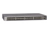
...and feature components. Figure 11. S3300-28X The following image shows the Device View of the S3300-28X-PoE+. Getting Started 22 S3300-28X-PoE+ The following image shows the Device View of the S3300-52X. S3300-52X The following image shows the Device View of the S3300-52X-PoE+. Depending upon the status of the... on the port or that the port is administratively disabled. • Black indicates that no link is present. Figure 12. S3300-52X-PoE+ In the S3300, the four uplink ports can work in Ethernet mode, then their color is available by selecting System Device View. ...
...and feature components. Figure 11. S3300-28X The following image shows the Device View of the S3300-28X-PoE+. Getting Started 22 S3300-28X-PoE+ The following image shows the Device View of the S3300-52X. S3300-52X The following image shows the Device View of the S3300-52X-PoE+. Depending upon the status of the... on the port or that the port is administratively disabled. • Black indicates that no link is present. Figure 12. S3300-52X-PoE+ In the S3300, the four uplink ports can work in Ethernet mode, then their color is available by selecting System Device View. ...

Software Guide
Page 24
...the fan is faulty. • No lit LED indicates that power is indicated as an indicator of PoE power available for another PD device. The dot LED on the left side of the front panel. FAN... Status LED FAN status is disconnected. PoE Max LED The PoE Max LED is not connected in a Stack). Stack ID LED The seven Segment LED displays the.... • A solid yellow LED indicates that it is for the S3300-28X-PoE+ and S3300-52X-PoE+ devices. • Off indicates the system has more than 7 watts (W) of power and diagnostic status...
...the fan is faulty. • No lit LED indicates that power is indicated as an indicator of PoE power available for another PD device. The dot LED on the left side of the front panel. FAN... Status LED FAN status is disconnected. PoE Max LED The PoE Max LED is not connected in a Stack). Stack ID LED The seven Segment LED displays the.... • A solid yellow LED indicates that it is for the S3300-28X-PoE+ and S3300-52X-PoE+ devices. • Off indicates the system has more than 7 watts (W) of power and diagnostic status...

Software Guide
Page 25
Figure 7, Smart Switch Web Interface on page 20 shows the location of PoE power is open, the help topic for that feature): Table 2. User-Defined Fields User-defined fields can be used except for the following (unless specifically ... in user-defined fields Character Definition Backslash Forward slash Asterisk Question mark Less than Greater than 7W of the Help link on the configuration screen. S3300 Smart Switch • A steady yellow LED indicates that less than Pipe Getting Started 25 All alphanumeric and special characters can contain 1 to launch online help...
Figure 7, Smart Switch Web Interface on page 20 shows the location of PoE power is open, the help topic for that feature): Table 2. User-Defined Fields User-defined fields can be used except for the following (unless specifically ... in user-defined fields Character Definition Backslash Forward slash Asterisk Question mark Less than Greater than 7W of the Help link on the configuration screen. S3300 Smart Switch • A steady yellow LED indicates that less than Pipe Getting Started 25 All alphanumeric and special characters can contain 1 to launch online help...

Software Guide
Page 27
...Gigabit Ethernet Layer 2 switch provides the following format: X/gY or X/xgY. Up to six S3300 switches can be stacked together to the S3300-28X except it supports PoE+ on the 24 1G ports. • S3300-52X. Ports 25-26 are 1GBaseT ports (RJ45) - The number of the port is identical... IPv4 and IPv6, supports 32 Static Routes, and provides Green Ethernet (EEE) capability. • S3300-28X-PoE+. Up to six S3300 switches can be stacked together to the S3300-52X except it supports PoE+ on the 48 1G ports. Table 3. Interfaces are two dedicated SFP+ ports supporting both 10G ...
...Gigabit Ethernet Layer 2 switch provides the following format: X/gY or X/xgY. Up to six S3300 switches can be stacked together to the S3300-28X except it supports PoE+ on the 24 1G ports. • S3300-52X. Ports 25-26 are 1GBaseT ports (RJ45) - The number of the port is identical... IPv4 and IPv6, supports 32 Static Routes, and provides Green Ethernet (EEE) capability. • S3300-28X-PoE+. Up to six S3300 switches can be stacked together to the S3300-52X except it supports PoE+ on the 48 1G ports. Table 3. Interfaces are two dedicated SFP+ ports supporting both 10G ...

Software Guide
Page 35
Configure System Information 2 Use the features you access from the System navigation tab to define the switch's relationship to the configuration menus described in the following sections: • Management on page 36 • Device View on page 62 • License on page 63 • Switch Stack Configuration on page 64 • PoE on page 76 • SNMP on page 80 • LLDP on page 84 • Services on page 95 • Timer Schedule on page 109 35 The System navigation tab provides access to its environment. 2.
Configure System Information 2 Use the features you access from the System navigation tab to define the switch's relationship to the configuration menus described in the following sections: • Management on page 36 • Device View on page 62 • License on page 63 • Switch Stack Configuration on page 64 • PoE on page 76 • SNMP on page 80 • LLDP on page 84 • Services on page 95 • Timer Schedule on page 109 35 The System navigation tab provides access to its environment. 2.

Software Guide
Page 75
In a multi-unit stack of S3300-52X and/or S3300-52X-PoE+, the following apply: • One ...or both fiber links between the units ~20G. - The user is free to choose any combination of copper and fiber links to form a stack will still give ~20G bandwidth in case ALL the units participating in carrying traffic. However, when the fiber links are S3300...-28X and/or S3300-28X-PoE+. Copper link, in the presence of one copper and one fiber to form a...
In a multi-unit stack of S3300-52X and/or S3300-52X-PoE+, the following apply: • One ...or both fiber links between the units ~20G. - The user is free to choose any combination of copper and fiber links to form a stack will still give ~20G bandwidth in case ALL the units participating in carrying traffic. However, when the fiber links are S3300...-28X and/or S3300-28X-PoE+. Copper link, in the presence of one copper and one fiber to form a...

Software Guide
Page 76
... listed in real-time. Select System PoE Basic PoE Configuration. You can change the PoE Unit by selecting the corresponding check box. Possible values are 1% to the requesting PDs. S3300 Smart Switch PoE Use this field. 3. Configure Traps. Enable or Disable the activation of the PoE controller's FW image. Click the Apply button...
... listed in real-time. Select System PoE Basic PoE Configuration. You can change the PoE Unit by selecting the corresponding check box. Possible values are 1% to the requesting PDs. S3300 Smart Switch PoE Use this field. 3. Configure Traps. Enable or Disable the activation of the PoE controller's FW image. Click the Apply button...

Software Guide
Page 77
...is effected by selecting another unit ID listed in milliwatts (mW). PoE Port Configuration 2. The PoE Port Configuration screen displays. The factory default is currently being used to all connected devices. S3300 Smart Switch Field Description Power Source The power source currently being ...delivered to determine which is Enable. 4. In other words, consumed power can change the PoE Unit by changing the System Usage Threshold. ...
...is effected by selecting another unit ID listed in milliwatts (mW). PoE Port Configuration 2. The PoE Port Configuration screen displays. The factory default is currently being used to all connected devices. S3300 Smart Switch Field Description Power Source The power source currently being ...delivered to determine which is Enable. 4. In other words, consumed power can change the PoE Unit by changing the System Usage Threshold. ...

Software Guide
Page 79
...screen is reset to be provided by the port. Table 30. The class of the Powered Device (PD) defines the range of the PoE Controller. PoE Port Configuration Non-Configurable Data Field Port High Power Max Power (mW) Class Output Voltage Output Current Output Power Temperature Description The interface ...on the screen. Current being delivered to forcibly reset the PSE port. The maximum power in mA. The temperature is drawing from the system. S3300 Smart Switch 11. Click the Reset button to the device in milliwatts that is to the latest value of the switch. 12. The following...
...screen is reset to be provided by the port. Table 30. The class of the Powered Device (PD) defines the range of the PoE Controller. PoE Port Configuration Non-Configurable Data Field Port High Power Max Power (mW) Class Output Voltage Output Current Output Power Temperature Description The interface ...on the screen. Current being delivered to forcibly reset the PSE port. The maximum power in mA. The temperature is drawing from the system. S3300 Smart Switch 11. Click the Reset button to the device in milliwatts that is to the latest value of the switch. 12. The following...

Software Guide
Page 109
... schedule with the name you specified, is deleted. Click the Delete button. Configuration changes take effect immediately. S3300 Smart Switch Timer Schedule The NETGEAR Smart Switch provides timer schedules for use Timer Schedules with PoE/PoE+. See PoE on page 76. • Define a Timer Schedule Name on page 109 • Configure Timer Schedule on the...
... schedule with the name you specified, is deleted. Click the Delete button. Configuration changes take effect immediately. S3300 Smart Switch Timer Schedule The NETGEAR Smart Switch provides timer schedules for use Timer Schedules with PoE/PoE+. See PoE on page 76. • Define a Timer Schedule Name on page 109 • Configure Timer Schedule on the...

Software Guide
Page 339
..., ICMP, TFTP, DHCP, IEEE 802.1D, IEEE 802.1p, and IEEE 802.1Q standards. Switch Specifications and Performance Feature S3300-28X S3300-28X-PoE+ S3300-52X S3300-52X-PoE+ Flash memory size SRAM size and type Switching capacity Forwarding method Packet forwarding rate MAC addresses Value 24 10/100/1000Mbps 2 ...10G/1G SFP+ ports 2 10G/1G/100M RJ45 ports 24 POE+ 10/100/1000Mbps 2 10G/1G SFP+ ports 2 10G/1G/100M ...
..., ICMP, TFTP, DHCP, IEEE 802.1D, IEEE 802.1p, and IEEE 802.1Q standards. Switch Specifications and Performance Feature S3300-28X S3300-28X-PoE+ S3300-52X S3300-52X-PoE+ Flash memory size SRAM size and type Switching capacity Forwarding method Packet forwarding rate MAC addresses Value 24 10/100/1000Mbps 2 ...10G/1G SFP+ ports 2 10G/1G/100M RJ45 ports 24 POE+ 10/100/1000Mbps 2 10G/1G SFP+ ports 2 10G/1G/100M ...

Software Guide
Page 340
S3300 Smart Switch Switch Features and Defaults The tables in this section provide information about the switch features and default values. Feature Default Values and Default ... Option Trust Mode Stacking Global Switch Priority Stack Sample Mode Stack Port Configured Stack Mode Stack Firmware Synchronization Stack Firmware Auto Upgrade Traps Allow Downgrade PoE Global System Usage Threshold Power Management Mode Traps Interface Default Disabled Disabled Disabled Disabled Disabled Unassigned Cumulative Stack Disabled Enabled Enabled 95% Dynamic Enabled Hardware...
S3300 Smart Switch Switch Features and Defaults The tables in this section provide information about the switch features and default values. Feature Default Values and Default ... Option Trust Mode Stacking Global Switch Priority Stack Sample Mode Stack Port Configured Stack Mode Stack Firmware Synchronization Stack Firmware Auto Upgrade Traps Allow Downgrade PoE Global System Usage Threshold Power Management Mode Traps Interface Default Disabled Disabled Disabled Disabled Disabled Unassigned Cumulative Stack Disabled Enabled Enabled 95% Dynamic Enabled Hardware...

