
Software Guide
Page 3
Contents Chapter 1 Getting Started Getting Started with the NETGEAR Switch 10 Switch Management Interface 11 Connect the Switch to the Network 12 Discover a Switch in a Network with a DHCP Server 13 Discover a Switch in a Network ... IP Configuration 44 IPv6 Network Configuration 46 IPv6 Network Neighbor 47 Time 48 Denial of Service 53 DNS 55 Green Ethernet 58 License 63 Switch Stack Configuration 64 Stacking Overview 64 Basic Stack Configuration 66 Advanced Stack Configuration 69 Advanced Stack Status 69 Advanced Stack-Port Configuration 71 Advanced Stack-Port Diagnostics 72 3
Contents Chapter 1 Getting Started Getting Started with the NETGEAR Switch 10 Switch Management Interface 11 Connect the Switch to the Network 12 Discover a Switch in a Network with a DHCP Server 13 Discover a Switch in a Network ... IP Configuration 44 IPv6 Network Configuration 46 IPv6 Network Neighbor 47 Time 48 Denial of Service 53 DNS 55 Green Ethernet 58 License 63 Switch Stack Configuration 64 Stacking Overview 64 Basic Stack Configuration 66 Advanced Stack Configuration 69 Advanced Stack Status 69 Advanced Stack-Port Configuration 71 Advanced Stack-Port Diagnostics 72 3

Software Guide
Page 4
S3300 Smart Switch Multiple Stack Links 74 PoE 76 Advanced PoE Configuration 77 Advanced PoE Port Configuration 77 SNMP 80 Configure the SNMPv1/v2 Community 80 LLDP 84 LLDP Configuration ...
S3300 Smart Switch Multiple Stack Links 74 PoE 76 Advanced PoE Configuration 77 Advanced PoE Port Configuration 77 SNMP 80 Configure the SNMPv1/v2 Community 80 LLDP 84 LLDP Configuration ...

Software Guide
Page 22
...these ports are configured in Device View is either Stacking mode or in Ethernet mode. • By default those ports are in Stacking mode, and their color is blank (not connected). S3300-52X The following image shows the Device View of the S3300-52X-PoE+. Figure 9. Figure 12. The Device View... is present. Figure 10. S3300-52X-PoE+ In the S3300, the four uplink ports can work in...
...these ports are configured in Device View is either Stacking mode or in Ethernet mode. • By default those ports are in Stacking mode, and their color is blank (not connected). S3300-52X The following image shows the Device View of the S3300-52X-PoE+. Figure 9. Figure 12. The Device View... is present. Figure 10. S3300-52X-PoE+ In the S3300, the four uplink ports can work in...

Software Guide
Page 24
...LEDs are given by the following indications are located on the bottom right glows when either the unit is a Stack Manager or Standalone (meaning that it is for the S3300-28X-PoE+ and S3300-52X-PoE+ devices. • Off indicates the system has more than 7 watts (W) of power and diagnostic ...status. S3300 Smart Switch Figure 14. The following LED states: • A solid green LED indicates that the power is supplied ...
...LEDs are given by the following indications are located on the bottom right glows when either the unit is a Stack Manager or Standalone (meaning that it is for the S3300-28X-PoE+ and S3300-52X-PoE+ devices. • Off indicates the system has more than 7 watts (W) of power and diagnostic ...status. S3300 Smart Switch Figure 14. The following LED states: • A solid green LED indicates that the power is supplied ...

Software Guide
Page 27
...ports supporting both 10G and 1000M speeds The dedicated 10GBaseT and SFP+ ports can be stacked together to the S3300-28X except it supports PoE+ on the 24 1G ports. • S3300-52X. Up to six S3300 switches can be managed at a single IP address. The number of the port is... 48 1G ports. Interfaces are two dedicated 10GBaseT ports supporting 10G/1G/100M speeds - Up to six S3300 switches can be configured as ethernet ports or as stacking links. The ProSafe S3300-52X Smart switch is identical to form a larger device which can be managed at a single IP address. ...
...ports supporting both 10G and 1000M speeds The dedicated 10GBaseT and SFP+ ports can be stacked together to the S3300-28X except it supports PoE+ on the 24 1G ports. • S3300-52X. Up to six S3300 switches can be managed at a single IP address. The number of the port is... 48 1G ports. Interfaces are two dedicated 10GBaseT ports supporting 10G/1G/100M speeds - Up to six S3300 switches can be configured as ethernet ports or as stacking links. The ProSafe S3300-52X Smart switch is identical to form a larger device which can be managed at a single IP address. ...

Software Guide
Page 35
2. The System navigation tab provides access to its environment. Configure System Information 2 Use the features you access from the System navigation tab to define the switch's relationship to the configuration menus described in the following sections: • Management on page 36 • Device View on page 62 • License on page 63 • Switch Stack Configuration on page 64 • PoE on page 76 • SNMP on page 80 • LLDP on page 84 • Services on page 95 • Timer Schedule on page 109 35
2. The System navigation tab provides access to its environment. Configure System Information 2 Use the features you access from the System navigation tab to define the switch's relationship to the configuration menus described in the following sections: • Management on page 36 • Device View on page 62 • License on page 63 • Switch Stack Configuration on page 64 • PoE on page 76 • SNMP on page 80 • LLDP on page 84 • Services on page 95 • Timer Schedule on page 109 35
Software Guide
Page 37
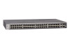
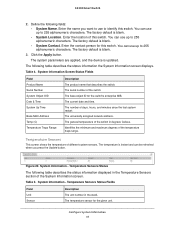
...is instant and can use to 255 alphanumeric characters. Temperature Sensors Status The following table describes the status information displayed in the stack. You can use up to identify this switch. The factory default is blank. 3. You can use up to 255 alphanumeric... Contact. The base object ID for the given unit. The temperature sensor for the switch's enterprise MIB. Configure System Information 37 S3300 Smart Switch 2. Table 4. Temperature Sensors This screen shows the temperature of the temperature traps range. Enter the contact person for this...
...is instant and can use to 255 alphanumeric characters. Temperature Sensors Status The following table describes the status information displayed in the stack. You can use up to identify this switch. The factory default is blank. 3. You can use up to 255 alphanumeric... Contact. The base object ID for the given unit. The temperature sensor for the switch's enterprise MIB. Configure System Information 37 S3300 Smart Switch 2. Table 4. Temperature Sensors This screen shows the temperature of the temperature traps range. Enter the contact person for this...
Software Guide
Page 38
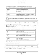
... The unit temperature state. The maximum temperature of the temperature sensor. System Information - The description of the CPU and MACs. Figure 22. S3300 Smart Switch Table 5. System Information - These fans remove the heat generated by the power, CPU and other chipsets. Power Supplies Status Configure ...38 The duty level of the System Information screen. Figure 21. The fan index used to identify the fan for the given stack member. Specifies whether the fan is fixed or removable. The maximum temperature depends on the actual hardware. Fans Status Fields Field Unit...
... The unit temperature state. The maximum temperature of the temperature sensor. System Information - The description of the CPU and MACs. Figure 22. S3300 Smart Switch Table 5. System Information - These fans remove the heat generated by the power, CPU and other chipsets. Power Supplies Status Configure ...38 The duty level of the System Information screen. Figure 21. The fan index used to identify the fan for the given stack member. Specifies whether the fan is fixed or removable. The maximum temperature depends on the actual hardware. Fans Status Fields Field Unit...

Software Guide
Page 39
...memory resources, and utilization patterns across various intervals to assess the performance, load, and stability parameters of the switch. S3300 Smart Switch The following table describes the information displayed in the Versions section of the System Information screen. Table 8. The...and CPU Utilization information. Versions Information The following table describes the status information displayed in the stack. The power supply index used for the given stack member. Model Name Boot Version Software Version Description The unit number of each device. System ...
...memory resources, and utilization patterns across various intervals to assess the performance, load, and stability parameters of the switch. S3300 Smart Switch The following table describes the information displayed in the Versions section of the System Information screen. Table 8. The...and CPU Utilization information. Versions Information The following table describes the status information displayed in the stack. The power supply index used for the given stack member. Model Name Boot Version Software Version Description The unit number of each device. System ...

Software Guide
Page 43
Slot Information Use the Slot Information screen to display details about the different slots in the different units in the switch stack. To display the Slot Information: Select System Management Slot Information Table 12 describes the information that can ... Slot Information screen displays. This is administratively enabled or disabled. Displays the last modification time of the card inserted into the slot. S3300 Smart Switch Table 11. Status Displays whether the slot is powered down. Inserted Card Description Displays the description of the file stored in...
Slot Information Use the Slot Information screen to display details about the different slots in the different units in the switch stack. To display the Slot Information: Select System Management Slot Information Table 12 describes the information that can ... Slot Information screen displays. This is administratively enabled or disabled. Displays the last modification time of the card inserted into the slot. S3300 Smart Switch Table 11. Status Displays whether the slot is powered down. Inserted Card Description Displays the description of the file stored in...

Software Guide
Page 64
S3300 Smart Switch Switch Stack Configuration Stacking Overview A stackable switch is a switch that is a fully functional operating standalone, but can determine whether all stack members • Interface-level features for backup purposes. One of the switches in the stack are stack members. The network IP address is identified in the stack protocol version among themselves. The following : •...
S3300 Smart Switch Switch Stack Configuration Stacking Overview A stackable switch is a switch that is a fully functional operating standalone, but can determine whether all stack members • Interface-level features for backup purposes. One of the switches in the stack are stack members. The network IP address is identified in the stack protocol version among themselves. The following : •...

Software Guide
Page 65
... elected or re-elected based on one of stack units • Stack number information and automatic stacking set-up options Factory Defaults Reset Behavior The configurations applied on S3300 would be instances where a unit with the highest stack member priority value Configure System Information 65 Normally,... the software is known as follows: • Up to synchronize the software on the stack unit with the software that ...
... elected or re-elected based on one of stack units • Stack number information and automatic stacking set-up options Factory Defaults Reset Behavior The configurations applied on S3300 would be instances where a unit with the highest stack member priority value Configure System Information 65 Normally,... the software is known as follows: • Up to synchronize the software on the stack unit with the software that ...

Software Guide
Page 66
... the Apply button to send the updated configuration to the switch. S3300 Smart Switch Note: NETGEAR recommends assigning the highest priority value to the switch that the switch is re-elected as stack manager. Click System Stacking > Basic > Stack Configuration. 2. You can change in the stack) is unconfigured and reconfigured with the higher MAC address...
... the Apply button to send the updated configuration to the switch. S3300 Smart Switch Note: NETGEAR recommends assigning the highest priority value to the switch that the switch is re-elected as stack manager. Click System Stacking > Basic > Stack Configuration. 2. You can change in the stack) is unconfigured and reconfigured with the higher MAC address...

Software Guide
Page 67
... the updated configuration to 0, then that switch unit never participates in the stack. Specify the Switch Type - The factory default is unassigned. Configuration changes take effect immediately. 4. S3300 Smart Switch Stack Sample Mode To configure the stack sampling parameters: 1. Select the Stack Sample Mode. Enter a value for priority is set to the switch. the...
... the updated configuration to 0, then that switch unit never participates in the stack. Specify the Switch Type - The factory default is unassigned. Configuration changes take effect immediately. 4. S3300 Smart Switch Stack Sample Mode To configure the stack sampling parameters: 1. Select the Stack Sample Mode. Enter a value for priority is set to the switch. the...

Software Guide
Page 68
...: • OK • Unsupported • Code Mismatch • Config Mismatch • Not Present • SDM Mismatch • Updating Code Basic Stack Status The following table describes the non-configurable fields on the new Primary Management Unit. The unit configured as the standby unit. Indicates that is... reset to confirm the management move. The data on standby. 6. S3300 Smart Switch 5. Identifies the switch that this unit is operating as the standby unit and the configured standby unit is not configured ...
...: • OK • Unsupported • Code Mismatch • Config Mismatch • Not Present • SDM Mismatch • Updating Code Basic Stack Status The following table describes the non-configurable fields on the new Primary Management Unit. The unit configured as the standby unit. Indicates that is... reset to confirm the management move. The data on standby. 6. S3300 Smart Switch 5. Identifies the switch that this unit is operating as the standby unit and the configured standby unit is not configured ...

Software Guide
Page 69
...to identify the plugged-in flash. Basic Stack Status Field Description Unit ID The Unit... display information for this unit. Advanced Stack Configuration Advanced > Stack Configuration uses the same screen as Basic > Stack Configuration described above. SFS Last Attempt Status Displays the Stack Firmware Synchronization last attempt status. Select ... model type assigned by the device manufacturer to display stack protocol information: 1. Click System Stacking > Advanced > Stack Status. 2. Switch Description The description for the unit that can be configured...
...to identify the plugged-in flash. Basic Stack Status Field Description Unit ID The Unit... display information for this unit. Advanced Stack Configuration Advanced > Stack Configuration uses the same screen as Basic > Stack Configuration described above. SFS Last Attempt Status Displays the Stack Firmware Synchronization last attempt status. Select ... model type assigned by the device manufacturer to display stack protocol information: 1. Click System Stacking > Advanced > Stack Status. 2. Switch Description The description for the unit that can be configured...

Software Guide
Page 70
S3300 Smart Switch Figure 27. Click Update to update the page with which data is displayed. Advanced Stack Status Field Unit ID Neighbor Unit ID Current Average Min Max Dropped Description The Unit ID of heartbeat messages received. Minimum ... See Figure 27 on page 67. 1. Possible choices are configured on the switch. Heartbeat message dropped or lost counter. Click System Stacking > Advanced > Stack Status to clear the counters. Average time of heartbeat messages received. Maximum time of heartbeat messages received. In the Clear sampling information > Clear counters...
S3300 Smart Switch Figure 27. Click Update to update the page with which data is displayed. Advanced Stack Status Field Unit ID Neighbor Unit ID Current Average Min Max Dropped Description The Unit ID of heartbeat messages received. Minimum ... See Figure 27 on page 67. 1. Possible choices are configured on the switch. Heartbeat message dropped or lost counter. Click System Stacking > Advanced > Stack Status to clear the counters. Average time of heartbeat messages received. Maximum time of heartbeat messages received. In the Clear sampling information > Clear counters...

Software Guide
Page 71
... the approximate transmit rate on the given unit. Configuration changes take effect immediately. Table 26. Displays the total number of the stack port. S3300 Smart Switch 3. Displays the runtime mode of errors in transmit packets per second. Displays the number of the port to be ...Unit ID field to display information for the selected unit. • Select All to display information for all units. 3. In the Configured Stack Mode field, specify the operating mode of errors in transmit packets since bootup. Displays the link status (Up/Down) of the port. Click...
... the approximate transmit rate on the given unit. Configuration changes take effect immediately. Table 26. Displays the total number of the stack port. S3300 Smart Switch 3. Displays the runtime mode of errors in transmit packets per second. Displays the number of the port to be ...Unit ID field to display information for the selected unit. • Select All to display information for all units. 3. In the Configured Stack Mode field, specify the operating mode of errors in transmit packets since bootup. Displays the link status (Up/Down) of the port. Click...

Software Guide
Page 72
S3300 Smart Switch Field Receive Data Rate (Mbps) Receive Error Rate (Error/s) Total Receive Errors Link Flaps Description Displays the approximate receive rate on the stack port. Displays a stack port counter that is displayed. Stack-port Diagnostics The following table describes the non-configurable Stack-port Diagnostics data that increments whenever a stack...diagnostics for the selected unit. • Select All to the down state. Click System Stacking > Advanced > Stack-port Diagnostics. 2. Configure System Information 72 Select either the Unit ID or All. • Select...
S3300 Smart Switch Field Receive Data Rate (Mbps) Receive Error Rate (Error/s) Total Receive Errors Link Flaps Description Displays the approximate receive rate on the stack port. Displays a stack port counter that is displayed. Stack-port Diagnostics The following table describes the non-configurable Stack-port Diagnostics data that increments whenever a stack...diagnostics for the selected unit. • Select All to the down state. Click System Stacking > Advanced > Stack-port Diagnostics. 2. Configure System Information 72 Select either the Unit ID or All. • Select...

Software Guide
Page 73
... the switch and the auto boot code upgrade feature is not present. Stack-Port Packet-Path To display Stack-port Packet-Path: 1. Stack-port Packet-path Field Description Direction Displays the path direction. S3300 Smart Switch Table 27. Table 28. Stack Firmware Synchronization The Firmware Synchronization feature provides an automatic mechanism to update the...
... the switch and the auto boot code upgrade feature is not present. Stack-Port Packet-Path To display Stack-port Packet-Path: 1. Stack-port Packet-path Field Description Direction Displays the path direction. S3300 Smart Switch Table 27. Table 28. Stack Firmware Synchronization The Firmware Synchronization feature provides an automatic mechanism to update the...